IJE TRANSACTIONS A: Basics Vol. 30, No. 4, (April 2017) 464-472
Please cite this article as: K. Azizi, M. Keshavarz Moraveji, Computational Fluid Dynamic- Two Fluid Model Study of Gas-Solid Heat Transfer in a Riser with Various Inclination Angles, International Journal of Engineering (IJE), TRANSACTIONS A: Basics Vol. 30, No. 4, (April 2017) 464-472
International Journal of Engineering
J o u r n a l H o m e p a g e : w w w . i j e . i rComputational Fluid Dynamic-
Two Fluid Model Study of Gas-Solid Heat Transfer
in a Riser with Various Inclination Angles
K. Azizi, M. Keshavarz Moraveji*
Department of Chemical Engineering, Amirkabir University of Technology (Tehran Polytechnic), Tehran, Iran
P A P E R I N F O
Paper history: Received 17 May 2016
Received in revised form 01 February 2017 Accepted 14 February 2017
Keywords: Fluidized Bed
Computational Fluid Dynamic Simulation Heat Transfer
Inclination Angle
A B S T R A C T
A two fluid model (TFM) was used to study gas-solid heat transfer in a riser with different inclination angles. A two dimensional pipe with 5.8 cm internal diameter and 5 meter length was chosen. Effect of bed angle and solid particles feed rate were studied on the heat transfer behavior of gas and solid particles. Obtained results from simulation are compared with the experimental data in the relevant literature. Heat transfer behavior of phases is different in an inclined pipe in comparison with vertical and horizontal pipes. It is found that higher air-solid Nusselt number, air temperature difference and particle temperature difference take place at the pipe with inclination angle equal to 45 degrees. Loading ratio enhancement increases gas temperature differences. At lower and higher loading ratio, particles temperature differences decreases and increases respectively with loading ratio enhancement.
doi: 10.5829/idosi.ije.2017.30.04a.02
NOMENCLATURE
CD Drag coefficient Greek Symbols
Cp Specific heat α Volume fraction
dp Solid diameter 𝛽𝑔𝑠 Gas-solid interphase exchange coefficient
ess Coefficient of restitution of the particle 𝛾Θ𝑠 Collision dissipation of energy
g Gravitational constant 𝛾𝑔𝑠0 Heat-transfer coefficient
Gk,g Production of turbulent kinetic energy ε Turbulence dissipation rate
Hgs Heat transfer between gas and solid 𝜂𝑔𝑠 Ratio between characteristic times
I Turbulent intensity Θ Granular temperature
I2D Second invariant of the deviatoric stress 𝜇𝑠,𝑐𝑜𝑙 Collisional part of the shear viscosity
k Turbulent kinetic energy tensor 𝜇𝑠,𝑓𝑟 Shear viscosity
k’ Thermal conductivity 𝜇𝑡,𝑔 Turbulent (or eddy) viscosity
𝑘Θ𝑠 Diffusion coefficient for granular energy 𝜇𝑠,𝑘𝑖𝑛 Kinematics viscosity
Nus Nusselt number 𝜈 Velocity
p Pressure Π𝑘,𝑔,Π𝜀,𝑔 Influence of the dispersed phase on the continuous phase
Pr Gas Prandtl number 𝜏̿ Reynolds stress tensor
Re Reynolds number Subscripts
T Time g Gas
V Velocity s Solid
t Turbulence
1*Corresponding Author’s Email:
1. INTRODUCTION
Solids moving with a gas stream in a pipeline can be found in many industrial processes. These include chemical, pharmaceutical, food, mineral industries, gaseous and particulate pollutant transport in the atmosphere and many other applications [1]. In many of these applications, heat transfer between gas and solid particles in the mixture and to the surroundings has a significant impact on the performance of the system [2]. High surface area of particles contributes to high heat transfer rates [3]. As a consequence, there has been widespread interest in the effect of heat transfer on the design of these systems [2].
Three main modes of heat transfer, bed to surface, interparticle and gas to particle heat transfer arise in gas solid flows and are important to study [4]. Heat transfer studies have been done for gas-solid flows in the literatures. Shi et al. [5] studied wall to bed heat transfer in a CFB. They showed that solid concentrations and solid movements in the vicinity of the heat transfer surface have a significant influence on the wall to bed heat transfer coefficient. Rajan et al. [6] studied the effect of solids feed rates, air velocity and particle size on the heat transfer of gas-solid in the vertical pneumatic conveyor. Mansoori et al. [4] studied turbulent gas solid flows and showed experimentally that variation of Nusselt number can be explained by the variation of the thermal turbulence intensity. Despite a significant amount of research on fluidized bed reactors, there are considerable uncertainties on their behavior. With the increased computational capabilities, computational fluid dynamic (CFD) has become an important tool for understanding these complex phenomena that occur between the gas phase and the particles in fluidized bed [1]. Two different approaches have been developed for application of CFD to gas-solid flows; Lagrangian method and Eulerian-Eulerian method [7-9]. Simulation of these systems with the Eulerian models using different CFD codes has shown the suitability of the approach for modeling these sytems [1]. Azizi et al. [10] used a two fluid model based on kinetic theory to study the heat transfer of gas solid flows in a vertical pneumatic conveyor and showed that heat transfer coefficient of gas –solid flow is greater than clean gas. Hamzehei and Rahimzadeh [11] used a multifluid Eulerian model incorporating the kinetic theory for solid phase to study the effect of particle size on heat transfer and hydrodynamics of a nonreactive gas-solid fluidized bed. Rajan et al. [12] simulated countercurrent gas-solid flow using two fluid model in a heat exchanger and compared their results with experimental data. They showed that heat transfer rates increase with increasing solid loading ratio and decreasing particle size. Behjat et al. [13] carried out a study on the gas-solid fluidized bed applying CFD
technique in order to investigate hydrodynamic and heat transfer phenomena. Gas-solid heat transfer during dilute phase pneumatic conveying was numerically investigated using an Eulerian-Eulerian approach by Rajan et al. [14]. Convective heat transfer between gas and particles and between gas and pipe wall, and conductive heat transfer between particles and pipe wall was modeled using distinct element method (DEM) by Li and Mason [2]. In their work, the gas phase was modeled as a continuum and the solid phase was modeled by DEM. Effect of collision-induced alterations of the flow dynamic on heat transfer in gas-solid flows in a vertical pipe have been presented by Chagras et al. [15].
In this study, the heat transfer of a two dimensional nonreactive gas-solid flow in a riser with different inclination angels was studied computationally. Computational study of riser with different inclination angles had been done for first time in this paper. A two fluid model (TFM) of multiphase incorporating the kinetic theory for solid particles with the 𝑘 − 𝜀 turbulent model was applied to simulate the gas-solid flow. Momentum exchange coefficient was evaluated using Gidaspow drag functions. The results of simulation were compared with the experimental data of Mokhtarifar et al. [16] for model validation.
2. MODELING
The Eulerian-Lagrangian discrete element model (DEM) and the Eulerian-Eulerian two-fluid model (TFM) have been developed for CFD modeling of gas-solid flows. In the DEM, the fluid is treated as a continuum phase by solving the Navier-Stokes equations, while the dispersed phase is solved by tracking a large number of particles through the flow filed. The dispersed phase can exchange momentum, mass and energy with the fluid phase.
In the TFM, both phases are treated as interpenetrating continuum phases [17]. In this method, the conservation equations for each of the two phases are derived. Therefore, two sets of coupled equations with similar mathematical structure should be solved. The success of this method depends on proper description of the forces between and acting on the phases.
In the present work, the governing equation of solid and gas phases are based on the Eulerian-Eulerian model. The governing equations of the gas-solid flow include the conservation of mass, momentum and energy [18, 19].
2. 1. Conservation of Mass The continuity
K. Azizi and M. Keshavarz Moraveji / IJE TRANSACTIONS A: Basics Vol. 30, No. 4, (April 2017) 464-472 466
𝜕
𝜕𝑡(𝛼𝑔𝜌𝑔) + ∇. (𝛼𝑔𝜌𝑔𝑣⃗𝑔) = 0 (1)
𝜕
𝜕𝑡(𝛼𝑠𝜌𝑠) + ∇. (𝛼𝑠𝜌𝑠𝑣⃗𝑠) = 0 (2)
where 𝛼𝑠 and 𝛼𝑔are the volume fraction of solid and gas
phase respectively. 𝜌 is density and 𝑣 is velocity.
2. 2. Conservation of Momentum The
conservation of momentum for the gas and solid phases are described by:
𝜕
𝜕𝑡(𝛼𝑔𝜌𝑔𝑣⃗𝑔) + ∇. (𝛼𝑔𝜌𝑔𝑣⃗𝑔𝑣⃗𝑔) = −𝛼𝑔∇𝑝𝑔+ ∇. 𝜏̅𝑔+
𝛼𝑔𝜌𝑔𝑔⃗ + 𝛽𝑔𝑠(𝑣⃗𝑠− 𝑣⃗𝑔)
(3)
𝜕
𝜕𝑡(𝛼𝑠𝜌𝑠𝑣⃗𝑠) + ∇. (𝛼𝑠𝜌𝑠𝑣⃗𝑠𝑣⃗𝑠) = −𝛼𝑠∇𝑝𝑔− ∇𝑝𝑠+ ∇. 𝜏̅𝑠+
𝛼𝑠𝜌𝑠𝑔⃗ + 𝛽𝑔𝑠(𝑣⃗𝑔− 𝑣⃗𝑠)
(4)
Here, 𝜏̅ is Reynolds stress tensor, g is the gravitational constant, and (−∇𝑝𝑠+ 𝛽𝑔𝑠(𝑣⃗𝑔− 𝑣⃗𝑠)) is an interaction
force (drag and buoyancy) representing the momentum transfer between gas and solid phases. This term is a statement of Darcy’s law where the reciprocal of 𝛽𝑔𝑠 is
the permeability dicided by the fluid viscosity [20]. Several drag models for gas-solid interphase exchange coefficient, 𝛽𝑔𝑠, is reported in the literature [10]; the
drag model of Syamlal-O’Brien, Gidaspow and Cao-Ahmadi. In this study, the drag model of Gidaspow was used.
The drag model of Gidaspow is combination of two drag model; Wen and Yu model for dilute flow and Ergun equation for dense flow [10]. When the volume fraction of gas, 𝛼𝑔, is greater than 0.8, 𝛽𝑔𝑠 is calculated
with equations from the Wen and Yu model.
𝛽𝑔𝑠=
3 4𝐶𝐷
𝛼𝑔𝛼𝑠𝜌𝑔|𝑣̅𝑠−𝑣̅𝑔| 𝑑𝑠 𝛼𝑔
−2.65 (5)
The drag coefficient, 𝐶𝐷, is related to the Reynolds
number by
𝐶𝐷=
24 𝑅𝑒𝑠
(1 + 0.15(𝑅𝑒𝑠)0.687) , 𝑅𝑒
𝑠< 1000 (6)
𝐶𝐷= 0.44 , 𝑅𝑒𝑠≥ 1000 (7)
𝑅𝑒𝑠=
𝛼𝑔𝜌𝑔(𝑣𝑔−𝑣𝑠)𝑑𝑝
𝜇𝑔 (8)
For dense flow (𝛼𝑔≤ 0.8), 𝛽𝑔𝑠 is calculated with Ergun
equation.
𝛽𝑔𝑠= 150
𝛼𝑠2𝜇𝑔
𝛼𝑠𝑑𝑠2+ 1.75
𝛼𝑠𝜌𝑔|𝑣̅𝑔−𝑣̅𝑠|
𝑑𝑠 (9)
The constitutive equation for solid phase stresses is given by: [1]
𝜏̅𝑠= 𝛼𝑠𝜇𝑠[∇𝑣⃗𝑠+ (∇𝑣⃗𝑠)𝑇] + 𝛼𝑠(𝜆𝑠−
2
3𝜇𝑠) ∇𝑣⃗𝑠𝐼̅ (10)
The granular temperature is proportional to the specific kinetic energy of the random fluctuating component of the particle velocity. It should be mentioned that granular temperature is quite different from solid-phase thermodynamic temperature. The transport equation for the solid-phase granular temperature is given as: [1]
3 2 𝜕
𝜕𝑡(𝛼𝑠𝜌𝑠Θ𝑠) + ∇. (𝛼𝑠𝜌𝑠𝑣⃗𝑠Θ𝑠) = (−𝑝𝑠𝐼̅ + 𝜏̅𝑠): ∇𝑣⃗𝑠+
∇. (𝑘Θ𝑠∇Θ𝑠) − 𝛾Θ𝑠+ 𝜙𝑔𝑠
(11)
The first term of the right hand side of this equation is the generation of energy by the solid stress tensor; the second term is the diffusion flux of granular energy (𝑘Θ𝑠is the diffusion coefficient); the third term is the collisional dissipation of energy; and the forth term is the energy exchange between the gas and solid. 𝛾Θ𝑠
which represents the rate of energy dissipation due to inelastic particle collisions is given as: [1]
𝛾Θ𝑠=
12(1−𝑒𝑠𝑠2)𝑔0,𝑠𝑠 𝑑𝑠√𝜋 𝛼𝑠
2𝜌
𝑠Θ𝑠3 2⁄ (12)
Random fluctuations cause the transfer of kinetic energy which is expressed as
𝜙𝑔𝑠= −3𝛽𝑔𝑠Θ𝑠 (13)
The solid phase pressure, 𝑝𝑠, consists of a collisional
and a kinetic part [21]:
𝑝𝑠= 𝛼𝑠𝜌𝑠Θ𝑠+ 2𝜌𝑠(1 + 𝑒𝑠𝑠)𝛼𝑠2𝑔0,𝑠𝑠Θ𝑠 (14)
where, 𝑒𝑠𝑠 is the restitution coefficient for particle
collisions and 𝑔0,𝑠𝑠 is the radial distribution.
𝑔0,𝑠𝑠= [1 − (
𝛼𝑠 𝛼𝑠,𝑚𝑎𝑥)
1 3⁄
]
−1
(15)
The solid phases shear viscosity consists of a collisional term:
𝜇𝑠,𝑐𝑜𝑙=45𝛼𝑠𝜌𝑠𝑔0,𝑠𝑠(1 + 𝑒𝑠𝑠) (Θ𝜋𝑠) 1 2⁄
(16)
A kinetic term:
𝜇𝑠,𝑘𝑖𝑛=
𝛼𝑠𝜌𝑠𝑑𝑠√Θ𝑠𝜋 6(3−𝑒𝑠𝑠) [1 +
2
5(1 + 𝑒𝑠𝑠)(3𝑒𝑠𝑠− 1)𝛼𝑠𝑔0,𝑠𝑠] (17)
And a friction term:
𝜇𝑠,𝑓𝑟=
𝑝𝑠𝑠𝑖𝑛𝜙
2√𝐼2𝐷 (18)
This parameter plays a significant role when the solid phase volume fraction gets close to the packing limit [1].
Hamzehei et al. [1] suggested the following equation which is solid bulk viscosity explaining the resistance of the granular particles to compression and expansion.
𝜆𝑠=
4
3𝛼𝑠𝜌𝑠𝑑𝑠𝑔0,𝑠𝑠(1 + 𝑒𝑠𝑠)√
Θ𝑠
𝑘Θ𝑠, the diffusion coefficient for the granular energy, is expressed by two the following equation [1].
𝑘Θ𝑠=
15𝛼𝑠𝜌𝑠𝑑𝑠√Θ𝑠𝜋 4(41−33𝜂) [1 +
12 5𝜂
2(4𝜂 − 3)𝛼
𝑠𝑔0,𝑠𝑠+ 16
15𝜋(41 − 33𝜂)𝜂𝛼𝑠𝑔0,𝑠𝑠]
(20)
where:
𝜂 =1
2(1 + 𝑒𝑠𝑠) (21)
2. 3. Internal Energy Conservation Neglecting
radiation heat transfer, the internal energy balances for the gas and solid phase are given by:
𝛼𝑔𝜌𝑔𝐶𝑝𝑔(
𝜕𝑇𝑔
𝜕𝑡 + 𝑣𝑔. ∇𝑇𝑔) = −𝐻𝑔𝑠 (22)
𝛼𝑠𝜌𝑠𝐶𝑝𝑠(𝜕𝑇𝜕𝑡𝑠+ 𝑣𝑠. ∇𝑇𝑠) = ∇. 𝛼𝑠𝐾𝑠∇𝑇𝑠+ 𝐻𝑔𝑠 (23)
The gas heat conductivity is negligible, so the heat diffusion term has been ignored. Solid granular conductivity is expressed by Ahmadi model [1].
𝐾𝑠= 0.1306𝜌𝑠𝑑𝑠(1 + 𝑒𝑠𝑠2) (𝑔1
0,𝑠𝑠+ 4.8𝛼𝑠+
12.1184𝑔0,𝑠𝑠𝛼𝑠2) √Θ𝑠
(24)
The heat transfer between the gas and the solid is:
𝐻𝑔𝑠= −𝛾𝑔𝑠0(𝑇𝑠− 𝑇𝑔) (25)
The heat transfer coefficient is related to the particle Nusselt number as follows.
𝛾𝑔𝑠0=
6𝑘𝑔′𝜀𝑠𝑁𝑢𝑠 𝑑𝑠2
(26)
𝑘𝑔′ is the thermal conductivity of the gas phase. The
Nusselt number is proposed by applying the Gunn correlation [13].
𝑁𝑢𝑠= (7 − 10𝛼𝑔+ 5𝛼𝑔2)(1 + 0.7𝑅𝑒𝑠0.2𝑃𝑟1 3⁄ ) +
(1.33 − 2.4𝛼𝑔+ 1.2𝛼𝑔2)𝑅𝑒𝑠0.7𝑃𝑟1 3⁄
(27)
where, 𝑅𝑒𝑠 is the relative solid Reynolds number and 𝑃𝑟
is the gas Prandtl number.
2. 4. Turbulent Model For turbulent flows,
viscosity in the momentum conservation equation is modified by a turbulence model which adds a turbulent viscosity to fluid of laminar flow. Viscosity of fluid is a property of fluid while the turbulent viscosity depends on flow conditions [10].
The 𝑘 − 𝜀 model includes the turbulent kinetic
energy (k) and the dissipation rate (𝜀) [22]. The Reynolds stress tensor for the gas phase is:
𝜏̅𝑔= −
2
3(𝜌𝑔𝑘𝑔+ 𝜌𝑔𝜇𝑡,𝑔∇. 𝑣⃗𝑔)𝐼̅ + 𝜌𝑔𝜇𝑡,𝑔[∇𝑣⃗𝑠+
(∇𝑣⃗𝑠)𝑇] (28)
The turbulent kinetic energy (k) and the dissipation rate (𝜀) are obtained from the following equations [10].
𝜕
𝜕𝑡(𝛼𝑔𝜌𝑔𝑘𝑔) + ∇. (𝛼𝑔𝜌𝑔𝑘𝑔𝑣⃗𝑔) = ∇. (𝛼𝑔
𝜇𝑡,𝑔 𝜎𝑘∇𝑘𝑔) +
𝛼𝑔𝐺𝑘,𝑔− 𝛼𝑔𝜌𝑔𝜀𝑔+ 𝛼𝑔𝜌𝑔Π𝑘,𝑔
(29)
𝜕
𝜕𝑡(𝛼𝑔𝜌𝑔𝜀𝑔) + ∇. (𝛼𝑔𝜌𝑔𝜀𝑔𝑣⃗𝑔) = ∇. (𝛼𝑔
𝜇𝑡,𝑔 𝜎𝜀 ∇𝜀𝑔) +
𝛼𝑔
𝜀𝑔
𝑘𝑔(𝐶1𝜀𝐶𝑘,𝑔− 𝐶2𝜀𝜌𝑔𝜀𝑔) + 𝛼𝑔𝜌𝑔Π𝜀,𝑔
(30)
where, Π𝑘,𝑔 and Π𝜀,𝑔 represent the influence of the solid
phase (dispersed phase) on the gas phase (continuous phase). The constitutive equations and coefficients are given in literature [1].
2. 5. Initial and Boundary Condition The initial
values of volume fraction and velocity of phases are specified for the entire computational domain. Initially, velocity of solid particle was set at zero. The temperature of both solid and gas phases was set at 300 K. Velocities and volume fraction of all phases were specified at the inlet of riser. A no slip wall condition at the pipe wall and constant pressure at outlet were used corresponding to momentum conservation equation. The boundary condition for the energy equation was set such that the wall is adiabatic. Table 1 shows the values of the parameters of the model used in the simulation.
3. RESULTS AND DISCUSSION
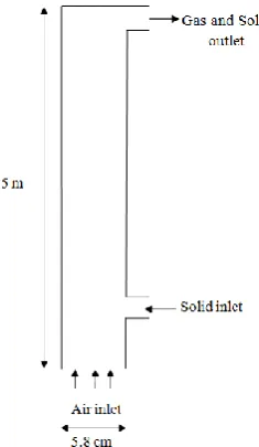
Simulation of the flow conditions is carried out using MFIX code. The 2D schematic of the pipe used in this simulation is shown in Figure 1. The computational domain used in this work is the same as the experimental work of Mokhtarifar et al. [16]. They used an inclined pipeline with length and height of D=0.058m and H=5m, respectively. Obtained results from simulation are compared with the experimental data in the relevant literature [16] to verify the availability of presented model. The domain was divided into 20*500 computation cells. The simulation was continued for 5 s and time step was set to 0.0001 s.
3. 1. Effects of Loading Ratio and Pipe Angle on
Air and Particle Temperature Variations of axial
air and particles temperature difference in different loading ratio and different pipe angles for 253 μm particle size, with air velocity of 18.5 m/s, are shown in Figure 2.
K. Azizi and M. Keshavarz Moraveji / IJE TRANSACTIONS A: Basics Vol. 30, No. 4, (April 2017) 464-472 468
TABLE 1. Values of Model Parameters Used in the
Simulations and Experiments
Property Value
Particle density 1500 kg/m3
Particle specific heat 800 J/kg-k
Particle thermal conductivity 0.80 W/m-k
Particle diameter 253 μm
Gas density 1.225 kg/m3
Restitution coefficient 0.99
Superficial gas velocity 18.5 m/s
Bed with 5.8 cm
Bed height 5 m
Solid feed rate 9, 15, 18, 22, 25 g/s
Pipe angle 0, 30, 45, 60, 90 degrees
Initial temperature 298 k
Air inlet temperature 440 k
Solid inlet temperature 300 k
With increasing inclination angles, the difference between simulation and results obtained by Mokhtarifar et al. [16] increased. However, this difference decrease as the pipe angle increased from 45 to 90. Also, it can be seen from the figure that temperature difference in horizontal and vertical configuration has less dependency on loading ratio.
It is showed that maximum pressure drop in a pipe takes place at an angle lower that 90 degrees [16]. Pressure drop in a pipe causes more interaction between phases and higher heat transfer between phases and consequently higher particle temperature.
Figure 1. The 2D schematic of the modeling domain
Figure 2. Variation of air and particle temperature difference
versus loading ratio at different pipe angles
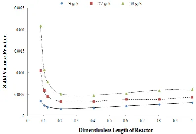
Contour plot of solid volume fraction, pressure and temperature of gas phase are shown in Figures 3-5. Also, gas pressure and temperature, before and after feeder are tabulated in Tables 2-3. In Figures 3-5, it could be seen that with changing the inclination angle the solid volume fraction and pressure drop will change. These changes will enhance heat transfer as it could be clearly seen from the Figures 6 (a-c). These results are in agreement with results presented in the literatures [16].
Similarly, temperature difference of particles increase as the pipe angle increase until it reaches to 45 degrees and then this difference decrease by changing the angle of pipe from 45 degrees to 90 degrees.
TABLE 2. Solid volume fraction before and after feeder in
different inclination angles
Solid Volume Fraction Inclination Angle
Before Feeder
After Feeder
Horizontal 0.00003 0.00064
45 Degrees 0.00004 0.01656
TABLE 3. Pressure drop before and after feeder in different inclination angles
Solid Volume Fraction Inclination Angle
Before Feeder
After Feeder
Horizontal 0.11528E+07 0.11526E+07
45 Degrees 0.11560E+07 0.11549E+07
Vertical 0.11531E+07 0.11528E+07
Figure 3. Contour plot of axial solid volume fraction at
different pipe angles
Figure 4. Contour plot of axial air pressure drop at different
pipe angles
Figure 5. Contour plot of axial air temperature at different
pipe angles
However, changing of particle temperature difference with loading ratio is different with what was obtained for air. It is observed that particles temperature decreases with increase of loading ratio at lower loading ratios, while it increases at higher loading ratios. It is showed that particle temperature is respectively proportional to air temperature difference and loading ratio directly and inversely [16].
Figure 6a. Axial solid volume fraction in a horizontal pipe
Figure 6b. Axial solid volume fraction in a pipe with
inclination angle of 45 degrees
Figure 6c. Axial solid volume fraction in a vertical pipe
K. Azizi and M. Keshavarz Moraveji / IJE TRANSACTIONS A: Basics Vol. 30, No. 4, (April 2017) 464-472 470
solid volume fraction in a higher particle feed rate is greater than that in a lower particle feed rate.
3. 2. Effects of Loading Ratio and Pipe Angle on
Air-Particle Nusselt Number The effect of the
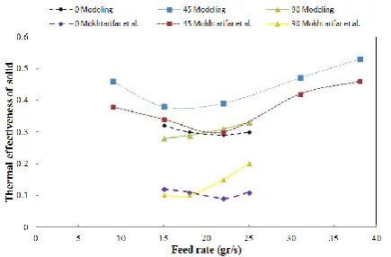
loading ratio on the air-particle Nusselt number for different pipe angles is illustrated in Figure 7. particle Nusselt number is changed slightly by Air-particle heat transfer coefficient if air heat conductivity is constant. Also, it is showed that at lower solids feed rates the heat transfer coefficient decreases with increase of loading ratio and at higher solids feed rates it increases with increase of loading ratio. Obtained results are in good agreement with results observed by Mokhtarifar et al. [16].
It can be seen from the Figure 7, Nusselt number increases as the pipe angle reaches to 45 and then it decrease by changing the angle of pipe from 45 degrees to 90 degrees.
As it is showed the Nusselt number is directly proportional to the heat transfer rate and inversely proportional to driving force and heat transfer area. It could be concluded that at the pipe angle of 45 degrees with a constant air velocity and particle feed rate, heat transfer rate has its maximum value and driving force is minimum [16]. Consequently, the Nusselt number would be maximized.
3. 3. Thermal Effectiveness of Air and Solid
Figures 8 (a-c) show thermal effectiveness of air at different loading ratio and different pipe angles. It is seen that thermal effectiveness of air increases as the loading ratio increase. Thermal effectiveness is directly proportional to air temperature difference. On the other hand, it is inversely proportional to inlet driving force. In this simulation, driving force which is defined as difference between air and articles initial temperature is constant. Therefore, it was expected that thermal effectiveness and air temperature difference have the same behavior as it is shown in Figure 2.
Figure 7. Variation of air - particle Nusselt number versus
loading ratio at different pipe angles
Figure 8a. Variation of thermal effectiveness of air versus
distance from feeder for horizontal pipe at different particles loading ratios.
Figure 8b.Variation of thermal effectiveness of air versus
distance from feeder for inclined pipe at different particles loading ratios.
Figure 8c. Variation of thermal effectiveness of air versus
distance from feeder for vertical pipe at different particles loading ratios.
Figure 9. Variation of thermal effectiveness of solid versus solid loading ratio at different pipe angles.
4. CONCLUSION
A two fluid model (TFM) of multiphase flows based on the kinetic theory was used for numerical modeling of gas-solid flow and heat transfer in a fluidized bed with different inclination angles and particles loading ratios. Obtained results from simulation are compared with experimental data. It is observed that heat transfer behavior of phases is different in an inclined pipe in comparison with vertical and horizontal pipes. Higher Nusselt numbers take place at pipe angles closer to 45 degrees. Also, it is observed that gas temperature differences increase as loading ratio increases. On the other hand, particles temperature difference decreases with increase of loading ratio at lower loading ratios, while it increases at higher loading ratios.
5. REFERENCES
1. Hamzehei, M., Rahimzadeh, H. and Ahmadi, G., "Computational and experimental study of heat transfer and hydrodynamics in a 2d gas− solid fluidized bed reactor", Industrial & Engineering Chemistry Research, Vol. 49, No. 11, (2010), 5110-5121.
2. Li, J. and Mason, D., "A computational investigation of transient heat transfer in pneumatic transport of granular particles", Powder Technology, Vol. 112, No. 3, (2000), 273-282. 3. Rajan, K., Srivastava, S., Pitchumani, B. and Mohanty, B.,
"Simulation of gas–solid heat transfer during pneumatic conveying: Use of multiple gas inlets along the duct", International communications in heat and mass transfer, Vol. 33, No. 10, (2006), 1234-1242.
4. Mansoori, Z., Saffar-Avval, M., Tabrizi, H.B. and Ahmadi, G., "Experimental study of turbulent gas–solid heat transfer at different particles temperature", Experimental thermal and fluid science, Vol. 28, No. 6, (2004), 655-665.
5. Shi, D., Nicolai, R. and Reh, L., "Wall-to-bed heat transfer in circulating fluidized beds", Chemical Engineering and Processing: Process Intensification, Vol. 37, No. 4, (1998), 287-293.
6. Rajan, K., Dhasandhan, K., Srivastava, S. and Pitchumani, B., "Studies on gas–solid heat transfer during pneumatic
conveying", International Journal of Heat and Mass Transfer, Vol. 51, No. 11, (2008), 2801-2813.
7. Mellin, P., Zhang, Q., Kantarelis, E. and Yang, W., "An euler– euler approach to modeling biomass fast pyrolysis in fluidized-bed reactors–focusing on the gas phase", Applied Thermal Engineering, Vol. 58, No. 1, (2013), 344-353.
8. Jin, G., Zhang, M., Fang, Z., Cui, Z. and Song, C., "Numerical study on spout elevation of a gas-particle spout fluidized bed in microwave-vacuum dryer", Journal of Food Engineering, Vol. 143, No., (2014), 8-16.
9. Azizi, S. and Mowla, D., "Cfd modeling of algae flash pyrolysis in the batch fluidized bed reactor including heat carrier particles", International Journal of Chemical Reactor Engineering, Vol. 14, No. 1, (2016), 463-480.
10. Azizi, S., Taheri, M. and Mowla, D., "Numerical modeling of heat transfer for gas-solid flow in vertical pipes", Numerical Heat Transfer, Part A: Applications, Vol. 62, No. 8, (2012), 659-677.
11. Hamzehei, M. and Rahimzadeh, H., "Experimental and numerical study of hydrodynamics with heat transfer in a gas− solid fluidized-bed reactor at different particle sizes", Industrial & Engineering Chemistry Research, Vol. 48, No. 6, (2009), 3177-3186.
12. Rajan, K., Srivastava, S., Pitchumani, B. and Mohanty, B., "Simulation of countercurrent gas–solid heat exchanger: Effect of solid loading ratio and particle size", Applied Thermal Engineering, Vol. 27, No. 8, (2007), 1345-1351.
13. Behjat, Y., Shahhosseini, S. and Hashemabadi, S.H., "Cfd modeling of hydrodynamic and heat transfer in fluidized bed reactors", International communications in heat and mass transfer, Vol. 35, No. 3, (2008), 357-368.
14. Rajan, K., Pitchumani, B., Srivastava, S. and Mohanty, B., "Two-dimensional simulation of gas–solid heat transfer in pneumatic conveying", International Journal of Heat and Mass Transfer, Vol. 50, No. 5, (2007), 967-976.
15. Chagras, V., Oesterlé, B. and Boulet, P., "On heat transfer in gas–solid pipe flows: Effects of collision induced alterations of the flow dynamics", International Journal of Heat and Mass Transfer, Vol. 48, No. 9, (2005), 1649-1661.
16. Mokhtarifar, N., Saffaraval, F., Saffar-Avval, M., Mansoori, Z. and Siamie, A., "Experimental modeling of gas–solid heat transfer in a pipe with various inclination angles", Heat Transfer Engineering, Vol. 36, No. 1, (2015), 113-122. 17. Azizi, S., Hosseini, S.H., Moraveji, M. and Ahmadi, G., "Cfd
modeling of a spouted bed with a porous draft tube", Particuology, Vol. 8, No. 5, (2010), 415-424.
18. Fenjan, S.A., Bonakdari, H., Gholami, A. and Akhtari, A., "Flow variables prediction using experimental, computational fluid dynamic and artificial neural network models in a sharp bend", International Journal of Engineering-Transactions A: Basics, Vol. 29, No. 1, (2016), 14.
19. Sheikhzadeh, G., Ghaffari, S. and Fakhari, M., "The effect of variable properties on rayleigh-benard convection in an enclosure filled with al2o3-eg-water nanofluid", International Journal of Engineering-Transactions C: Aspects, Vol. 26, No. 12, (2013), 1411.
20. Gidaspow, D., "Multiphase flow and fluidization: Continuum and kinetic theory descriptions, Academic press, (1994).
21. Mathiesen, V., Solberg, T. and Hjertager, B.H., "An experimental and computational study of multiphase flow behavior in a circulating fluidized bed", International Journal of Multiphase Flow, Vol. 26, No. 3, (2000), 387-419. 22. Ayremlouzadeh, H. and Ghafouri, J., "Computational fluid
K. Azizi and M. Keshavarz Moraveji / IJE TRANSACTIONS A: Basics Vol. 30, No. 4, (April 2017) 464-472 472
Computational Fluid Dynamic-
Two Fluid Model Study of Gas-Solid Heat Transfer
in a Riser with Various Inclination Angles
K. Azizi, M. Keshavarz Moraveji
Department of Chemical Engineering, Amirkabir University of Technology (Tehran Polytechnic), Tehran, Iran
P A P E R I N F O
Paper history: Received 17 May 2016
Received in revised form 01 February 2017 Accepted 14 February 2017
Keywords: Fluidized Bed
Computational Fluid Dynamic Simulation Heat Transfer
Inclination Angle
ديكچ ه
تبسن فلتخم یایاوز اب رزیار کی رد دماج و زاگ زاف ود نیب ترارح لاقتنا یسررب روظنم هب یلایس ود لدم هلاقم نیا رد
عافترا اب هلول کی ،روظنم نیا هب .دش هدرب راک هب قفا هب 5
یلخاد رطق و رتم 8
/ 5 اب رتسب هیواز رثا .دش یسررب رتم یتناس
زا هدمآ تسد هب جیاتن .دش هعلاطم دماج تارذ و زاگ زاف نیب ترارح لاقتنا یور رب رتسب هب دماج تارذ دورو خرن و قفا
فلتخم یایاوز رد ترارح لاقتنا دنیآرف یط اهزاف راتفر .دش هسیاقم تلااقم رد هدش هئارا یبرجت جیاتن اب یزاس هیبش
تخا ،تلسان ددع هک دش هدهاشم .دوب توافتم هیواز اب هلول رد هدش صخشم طاقن رد تارذ یامد فلاتخا و اوه یامد فلا
45 هلول رگید هب تبسن هجرد .دش اوه یامد فلاتخا رد شیازفا هب رجنم دماج تارذ دورو خرن رد شیازفا .تسا رتشیب اه
خرن رد تارذ یامد فلاتخا شهاک و شیازفا هب رجنم بیترت هب تارذ دورو خرن شیازفا یفرط زا دش لااب و نییاپ یدورو
.