TECHNICAL NOTE
AN
OPTIMAL
SELECTION
OF
INDUCTION
HEATING
CAPACITANCE
BY
GENETIC
ALGORITHM
CONSIDERING
DISSIPATION
LOSS
CAUSED
BY
ESR
G. R. Arab Markadeh*
Department of Engineering, Shahrekord University, Shahrekord, Iran, [email protected]
E. Daryabeigi
MSc Student, Islamic Azad University and Member of Young Researcher Club, Najafabad branch, Isfahan, Iran, [email protected]
*Corresponding Author
(Received: May 6, 2008 – Accepted in Revised Form: March 11, 2010)
Abstract In design of a parallel resonant induction heating system, choosing a proper capacitance for the resonant circuit is quite important. The capacitance affects the resonant frequency, output power, Q-factor, heating efficiency and power factor. In this paper, the role of equivalent series resistance (ESR) in the choice of capacitance is significantly recognized. Optimal value of resonance capacitor is achieved by using genetic algorithm method under voltage constraint for maximizing the output power of an induction heater, while minimizing the power loss and inverter switching frequency at the same time. Based on the equivalent circuit model of an induction heating system, the output power, and the capacitor losses are calculated. The effectiveness of the proposed method is verified by computer simulations.
Keywords Induction Heating, Capacitance, Genetic Algorithm, Switching Frequency, Equivalent Series Resistance.
ﻩﺪﻴﻜﭼ
ﺭﻮﮐﮏﻳ ﯽﺣﺍﺮﻃ ﺭﺩ ﻩ
ﺖﻴﻤﻫﺍﯼﺍﺭﺍﺩﺪﻳﺪﺸﺗ ﺭﺍﺪﻣﯼﺍﺮﺑﺐﺳﺎﻨﻣ ﻥﺯﺎﺧﺏﺎﺨﺘﻧﺍ،ﯼﺯﺍﻮﻣﯽﺴﻧﺎﻧﻭﺯﺭ ﯽﺋﺎﻘﻟﺍ
ﺪﺷﺎﺒﻴﻣ ﯼﺩﺎﻳﺯ
.
ﺐﻳﺮﺿ ،ﯽﺟﻭﺮﺧﻥﺍﻮﺗ،ﺲﻧﺎﻧﻭﺯﺭﺲﻧﺎﮐﺮﻓﺮﺑﻥﺯﺎﺧ ﻦﻳﺍ Q
ﺮﺛﺍﻥﺍﻮﺗﺐﻳﺮﺿ ﻭﯽﺗﺭﺍﺮﺣﻥﺎﻣﺪﻧﺍﺭ،
ﺩﺭﺍﺬﮔﯽﻣ
.
ﻝﺩﺎﻌﻣﯼﺮﺳ ﺖﻣﻭﺎﻘﻣﺶﻘﻧ ﺖﻴﻤﻫﺍﻭﻥﺯﺎﺧ ﺐﺳﺎﻨﻣﺏﺎﺨﺘﻧﺍﻪﻟﺎﻘﻣﻦﻳﺍﺭﺩ (ESR)
ﺭﺍﺮﻗﻪﺟﻮﺗ ﺩﺭﻮﻣ
ﺖﺳﺍ ﻪﺘﻓﺮﮔ
.
ﮔ ﺮﻈﻧﺭﺩ ﺎﺑ،ﯽﻳﺎﻘﻟﺍﻩﺭﻮﮐﺪﻳﺪﺸﺗ ﻥﺯﺎﺧﻪﻨﻴﻬﺑ ﺭﺍﺪﻘﻣﮏﻴﺘﻧﮊﻢﺘﻳﺭﻮﮕﻟﺁ ﺯﺍﻩﺩﺎﻔﺘﺳﺍﺎﺑ ﺮ
ﺖﻳﺩﻭﺪﺤﻣﻦﺘﻓ
ﻥﺍﻮﺗﺕﺎﻔﻠﺗﺶﻫﺎﮐﻭﺮﺗﺭﻮﻨﻳﺍﯽﻧﺯﺪﻴﻠﮐﺲﻧﺎﮐﺮﻓﺶﻫﺎﮐﻭﯽﺟﻭﺮﺧﻥﺍﻮﺗﺶﻳﺍﺰﻓﺍﺭﻮﻈﻨﻣﻪﺑ،ﺎﻬﭽﻴﺋﻮﺳﻭﻥﺯﺎﺧﮊﺎﺘﻟﻭ ﺪﻳﺁﯽﻣ ﺖﺳﺪﺑ ﯽﻧﺯﺎﺧ
.
ﺧﺕﺎﻔﻠﺗ ﻭ ﯽﺟﻭﺮﺧ ﻥﺍﻮﺗ ﺭﻮﮐ ﻢﺘﺴﻴﺳﮏﻳ ﻝﺩﺎﻌﻣ ﺭﺍﺪﻣ ﯼﺎﻨﺒﻣﺮﺑ ﯽﻧﺯﺎ
ة
ﻪﺒﺳﺎﺤﻣﯽﺋﺎﻘﻟﺍ
ﯽﻣ ﺪﻧﻮﺷ
.
ﺖﺳﺍﻪﺘﻓﺮﮔﺭﺍﺮﻗﯽﺳﺭﺮﺑﺩﺭﻮﻣﯼﺮﺗﻮﻴﭙﻣﺎﮐﯼﺯﺎﺳﻪﻴﺒﺷﺎﺑﯼﺩﺎﻬﻨﻨﺸﻴﭘﺵﻭﺭﺩﺮﮑﻠﻤﻋ
.
1. INTRODUCTION
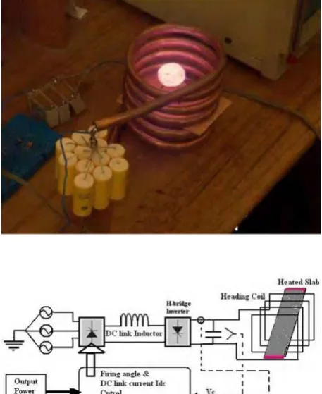
Induction heating is nowadays the most commonly used method in commercial production applications, especially in semi-solid metal processing, because it is a non-contact, clean, compact and fast method and the input power can be easily controlled. However, induction heating has its inherent drawback of non-uniform heating due to the so-called skin effect, end effect and
resonant frequency [2-3]. A typical parallel resonant inverter circuit for induction heater is shown in Fig. 1.
In the parallel resonant inverter, if the switching frequency is closed to the resonant frequency, higher voltage is generated at the capacitor bank [4]. However, due to the limit in the voltage tolerance of the capacitor bank, the inverter output voltage VC needs to be limited below the rated voltage
V
max. Also, the inverter costs and losses are increased by increasing the switching frequency. One method of limitingV
C is to reduce the DC-link currentI
dc by increasing the firing angle of the rectifier, however, the reduction ofI
dc decreases the output power.For example, at the mini-mill in a POSCO steel plant, eight induction heaters of load commutated type were installed to heat thin slabs for next milling process in the continuous casting plant. The rated output power of each induction heater is 1.5 MW. However, there were two problems: One was the insufficiency in the output power, and the other was the frequent damages of the capacitor bank. Insufficiency in output power was caused by a poor power factor of the inverter. On the other hand, the damage to the capacitor bank was due to a little voltage margin between
V
C andV
max, and it resulted in a large power dissipation in the capacitor causing a high temperature rise.Several attempts have been proposed to solve these problems such as optimal design of power devices [5], and proper control of the inverter switches [3] [6].
Various optimization methods, such as direct search method, evolution strategy (ES) and simulated annealing method (SAM) were applied to the optimal design of induction heater [6]. Several different Artificial Intelligence (AI) techniques, such as expert system (ES), fuzzy logic (FL), neural network (NN) or biologically-inspired (BI) genetic algorithm (GA) have recently been applied in power electronic applications [7-11]. In [12], an optimal value of the capacitance under the voltage constraint was found based on the Lagrange multiplier. In the mentioned method the switching frequency was not considered as an important parameter in the capacitance selection. As well as, calculating the optimum capacitance
needs to solve two nonlinear complex algebraic equations.
The GA as well as the evolutionary computation techniques is based on principles of evolution [13, 14]. Basically, the GA method solves optimization problem by a search process resulting in best solution.
A few researches have been proposed for genetic algorithm in induction heating [15-17]. In [15], a method for designing optimal passive and active shields for axisymmetric induction heaters. Such shields are needed to protect human operators and external electronic equipment from stray magnetic fields. The method uses a genetic algorithm to minimize an objective function in order to optimum shield designing.
In [16] and [17], based on the analysis of the characters of genetic algorithm and particle swarm optimization, a new hybrid genetic algorithm was presented for transverse flux induction heating. It is known, the capacitance value of the capacitor bank affects the overall operating factors of induction heater such as resonant frequency, Q-factor, efficiency, and power factor [18]. So another approach for optimization of induction heater operation is the selection of LC capacitance. In this work, we propose a method to choose an optimal capacitance valueCopt, which maximizes the output power, and at the same time, minimizes the capacitor loss with attention to switching frequency considerations.
An optimal value of the capacitance is found by defining an objective function that contains the output power, power loss, switching frequency and efficiency. At the first approach an equivalent model of the induction heater is developed based on previous works [12], [18]. The heating coil and slab is modeled as an inductance plus a series resistance, and the capacitor bank. Where Real capacitors have loss components such as dielectric loss and resistances of electrolyte and foil [19]. These loss terms are summed to be an equivalent series resistance (ESR), and capacitors are modeled roughly as a series combination of a capacitor and an ESR.
introduction of GA and its equations are presented; in continue simulation results is investigated in V section.
2. PROBLEM FORMULATION
A.Equivalent Circuit
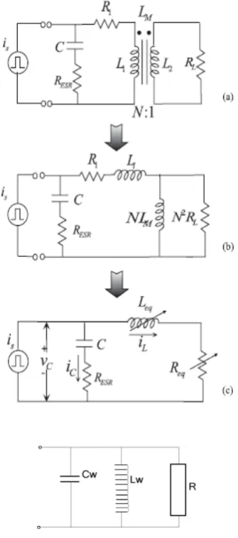
In general, the heating coil and the load are modeled as a transformer with a single turn secondary winding as shown in Figs. 2 and 3(a). Almost all magnetic flux generated by the induction coil (primary winding) penetrates into the slab (secondary winding). Hence, in the secondary circuit no leakage inductance appears and the coupling coefficient is equal to one. The secondary circuit can be moved to the primary part as shown in Fig. 3(b). The slab resistance RL for one turn coil is given by:
, ) 2 ( 2
l b A
L RL
(1)
Where L and A are the length and area of eddy current, l is the effective length of the slab occupied by one turn coil and b and w are defined in Fig. 2, δand ρare skin depth almost distributed over the surface of slab and electrical resistivity of the material. Simplified equivalent model for a transformer can be represented in Fig. 3(c) by an
equivalent inductanceLeqand resistanceReq. These equivalent parameters depend on several
variables including the shape of the heating coil, the spacing between the coil and slab, the electrical conductivity, the magnetic permeability of the slab, and the angular frequency of the varying current
S.,
2 21
A
L
L
L
eq
(2),
2
1 L
eq
R
A
R
R
(3)Where
R
1 denotes the resistance of the heating coil,R
Ldenotes the resistance of the heated slab, andA
sL
M/
s2L
22
R
L2 .It must be noted that the inductance of heating coilL
1 is not ffectedby the existence of the slab in the heating coil, since at about 1100 oC temperature the permeability of the iron slab is equal to that of air, i.e., μ= 4π × 10−7 (H/m).
To represent the power dissipation in the capacitor bank, it is modeled by a pure capacitance C and an Figure 1. a) A model of Induction heater, b) Block diagram of induction heating system.
Figure 2. Model of slab for one turn coil.
equivalent series resistance (ESR)
R
ESR The rectifier and H-bridge inverter of the induction heater are represented by a square waved current source whose magnitude is equal to the DC-link currentI
dc. Therefore, the current source expanded in a Fourier series is described as follows:
1 sin 4 ) ( n s dcs n t
n I t
i
=1, 3, 5 … (5)The first harmonic amplitude is equaled as follows:
/
4
dcs
I
I
(6)The current through Req and
R
ESR are represented byi
L andi
C, respectively. The phasor expression ofi
L andi
Care described as follows:, s I ESR Z C Z R Z L Z ESR Z C Z R Z L Z C V L I
(7)
, s ESR C R L R L ESR C C C I Z Z Z Z Z Z Z Z V I (8)
Where
V
C andI
sare the phasors ofv
C andi
s andV
C
Z
t
I
s . In Fig. 3(c), the power consumption is accomplished by equivalent resistor Req and ESRR
ESRof the capacitor bank. Therefore, the output power of the induction heaterout
P
and the capacitor lossP
loss are given by:, ) 1 ( ) ( 8 2 1 2 ) ( 2 2 2 2 2 2 2 eq eq s eq s s dc eq s ESR C R L ESR C eq L out R CL j C k R C j k I Z I Z Z Z Z Z Z Z I C P (9) , ) 1 ( ) ( ) ( 8 2 1 2 ) ( 2 2 2 2 2 2 2 C k CL j C k R C L j R C I Z I Z Z Z Z Z Z Z I C P eq s eq s eq s eq s dc ESR s ESR C R L R L ESR C loss (10)
Where
I
L,
I
Cdenote the peak ofi
L,
i
Crespectively. It is noted thatP
out andP
loss are function of capacitance C, since all the parameters except capacitance are known values in (9) and (10). Figure 3. (a) Based circuit of the induction heater. (b)3. OPTIMAL CAPACITANCE FOR INIMIZING DEFINED OBJECT FUNCTION
USING AN ANALYTIC METHOD
In the load commutated inverter, the switching frequency of the inverter must be higher than the resonant frequency of the L-C load to guarantee commutation of the thyristors [20]. Hence, for more suitable value for the inverter while working close to the resonant frequency, we let
a
1
.
1
0, and then the voltage constraint is given by , 4 ) 1 . 1 ( )(j I Z J 0 I Vmax
Z
VC t s s t dc (11)
Where
V
max is rated voltage of the capacitor bank andZ
t is total impedance of capacitor bank and heating parts. One can see thatZ
t(
j
1
.
1
0)
is also a function of capacitance, since
0
1
/
L
WC
W . The aim is to find an optimal capacitance value that maximize the output power of the induction heater and minimize the capacitor losses simultaneously under the voltage constraint (11). If the object function is selected asP
out
P
loss, maximizingP
out
P
lossis equivalent to maximizingout
P
and at the same time minimizingP
loss. MaximizingP
out
P
loss, with the (11) constraint, it leads to apply Kuhn-Tucker theorem [21]. The cost function is defined by
),
4
1
.
1
(
.(
)
(
)
(
)
(
0max t dc
loss out
I
J
Z
V
C
P
C
P
C
J
(12)Where
0
is Lagrange coefficient. Maximum point is defined by:, 0 C
J (13)
. 0 ) 4 ) 1 . 1 (
( max 0
V Zt j Idc
(14)
Finding the solution Copt for nonlinear algebraic (13) and (14) is too complex to be handled by hand. Therefore, Copt was found for a specific example by symbolic manipulation and numerical approach provided by MATLAB.
Finally in [12], using the mentioned method, the resulting capacitance was obtained as C126F, with
L
eq
8
.
3
H
4. OPTIMAL SELECTION OF APACITANCE USING GENETIC ALGORITM
Select of a suitable performance index or objective function is extremely important for the design of induction heating. The present research work considers a performance index that can be written in the general form as (15) and the optimal induction heating parameters shall be obtained by minimizing J. The optimization problem is selection of suitable capacitance, in order to increase the output power, decrease the ESR losses under the capacitance voltage and switching frequency constraints. , 87 . 0 100 995 . 0 )) ( ) ( ( 1 ) 1 ) ( ( 0005 . 0 ) 1 ) ( ( 2 PU p out eq s PU p loss out out out P C f c P c P J (15) Where ) ( ) ( ) ( c P c P c P loss out out
is the efficiency and
) (PU
pout is the per unit output power.
The capacitance voltage limitation is the same as (11).
The objective function J is defined based on the following subjects: a) lower switching frequency, since higher switching frequency causes to higher switching losses of inverter switches, b) higher efficiency, c) increase the output power, d) lower
power losses of ESR and e) lower capacitance value.
So, minimization of J is equal to maximizing of loss
out
P
P
,output power and defining suitable and minimum values off
SandCeq, maximum and suitable efficiency.Optimization starts with a randomly generated population of individuals. Then, entering in a loop over the generations, one needs to evaluate the objective value (i.e., performance) of each individual, and attributes a fitness ranking that will drive the selection process. The evaluation of the objective value is typically the most time-consuming step of the GA procedure as it involves several simulations (one for each individual). Selection determines the individuals that will reproduce, with better chances attributed to fitter individuals. Three commonly used methods for the selection are the roulette wheel, the stochastic universal sampling strategy and the binary tournament. After the reproduction population is determined, a crossover operator combines couples of parents to create offspring. A low-probability mutation operator then modifies randomly some characteristics of children produced by the crossovers. In order to avoid regression in the performance through the process, many authors use elitism. After verifying the stopping criterions of the loop over generations, the offspring becomes the new initial population and the process continues. A maximum number of generations and/or a maximum number of generations without improvement of the best individual generally act as stopping criterions.
5. SIMULATION RESULTS
Simulation was performed with MATLAB software. The parameters of POSCO induction heater were utilized in this simulation are given in table (1).
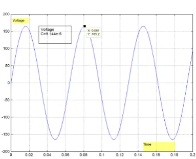
With the use of GA, the optimal capacitance value is found to be
C
W
9
.
144
[
F
]
by minimization (15) under the voltage constraint of (11). GA parameters are given in table (2). The result of GA performance is show in Fig. 4, that leads to minimum value of object function J.Figure 5- altering output power with frequency.
Figure 6- d( Pout)/d(fs).
Curve of output power
P
outversus switching frequencyf
S is indicated in Fig. 5. By attention to this Figure, increasing to switching frequency, decreases the output power, such that the end of curve, with increasing the frequency, there will not any change to output power. Therefore optimal and suitable frequency in order to increasing the output power is depicted in Figs. 5 and 6. In Fig. 6, the derivative e ofP
outversusf
S Figure is shown. After the characterized point on the curve, the output power will not acceptable changes with frequency increasing. As swell as the capacitance voltage of induction heater is shown in Fig. 7. The induction heater simulation parameters are the same as used in [12].In compared to achieved results in [12], the optimum capacitance was obtained
f
C
126
withP
out
64.287
kw
,1.0882%
9
, and our cost function with thoseresults was J 1.0183
But the achieved results in this paper are
f
C
9.1439
withP
out
74.479
kw
,%
9718
.
7
9
, and minimum cost function is1.01615
J .
As well as, finding the solution Copt needs to solve two nonlinear complex algebraic equations by MATLAB. Furthermore the proposed method is very sensitive to induction heater parameters.
6. CONCLUSION
This paper suggests a new method to select the optimal value of resonance capacitor for the induction heater. The optimal solution is found with genetic algorithm using a new objective function that includes output power, loss power, efficiency and switching frequency of inverter switches under the capacitance voltage constraint. This optimal choice is thought to contribute to increasing the life time of the capacitor bank and generating a maximum output power with higher efficient. Results of simulation are emphasized the improve efficiency and decreasing switching frequency in comparison with analytical method which is very complex and parameter dependent technique.
7. REFERENCES
1. H. Jiang, T.H. Nguyen, M. Prud’homme,” Optimal control of induction heating for semi-solid aluminum alloy forming”, Elsevier, Journal of Materials
Processing Technology, vol. 189, 2007, pp. 182–191.
2. Y. Kwon, S. Yoo, and D. Hyun, “Half-bridge series resonant inverter for induction heating applications with load- adaptive PFM control strategy”, IEEE-APEC
Proc., pp. 575-581, 1999.
3. W. S. Choi, I. Ju Pa, D. Yun Lee and D. S. Hyun,” A New Power Control Scheme of Class-D Inverter for Induction Heating Jar Application with Constant Switching Frequency”, Conf. IEEE Indus. Electron.
Pp. 784-789, Soc. Nov. 2 - 6, 2004, Buean, Korea. 4. F.P. Dawson, and P. Jain, “A comparison of load
commutated inverter systems for induction heating and melting applications”, IEEE Trans. Power Electronics, Vol. 6, No. 3, pp. 430 -441, July 1991.
5. M. Horii, N. Takahashiand T. Narita,” Investigation of TABEL I. PARAMETERS OF INDUCTION HEATING
] [ 949 .
19
H
w
L
] [ 0908 .
0
L
R
] [
1700V
MAX
V
] [
1300 A
s
I
]
.
[
10
35
.
1
4
f
K
TABEL II. PARAMETERS OF GA Population size 18
Mutation rate 0.15
generations 100
Number of Variable 1
Bit of each Variable 24
best object 1.01615480747
Evolution Strategy and Optimization of Induction Heating Model”, IEEE Trans. on Mag. vol. 36, no. 4, pp. 1085-1088, Jul. 2000.
6. Y. Favennec , V. Labb_e, F. Bay, “ Induction heating processes optimization a general optimal control approach”, Elsevier, Journal of Computational
Physics, vol. 187, 2003, pp. 68–94.
7. B. K. Bose, “Expert system, fuzzy logic, and neural network applications in power electronics and motion control,” Proc. IEEE, vol. 82, pp. 1303–1323, Aug. 1994.
8. J. Zhao and B. K. Bose, “Neural network based waveform processing and delayless filtering in power electronics and ac drives,” IEEE Trans. Ind. Electron., vol. 51, no. 5, pp. 981–991, Oct. 2004.
9. M.R.Jamaly, A. Armani. M.Dehyadegari, C.Lucas, Z. Navabi, "Emotion on FPGA: model driven approach".
Expert System with Applications. ELSEVIER, vol. 36,
no. 4, May 200, pp. 7369–7378
10. M. Jannatian , H. K. Karegar, H. Askarian Abyaneh and G. Heidari, “A Novel Fuzzy and Artifitial Neural Network Presentation of Overcurrent Relay Charachteristics”, International Journal of
Engineering, Transactions A: Basics Volume 16 - 3 -,
Sept. 2003, Art. #2, pp. 233-246.
11. R. Yazdanpanah and J. Soltan, “Rbust Backstepping Control of Induction Motor Drives using Artifitial Neural Networks and Sliding Mode Flux Observer”,
International Journal of Engineering, Transactions
A: Basics, Volume 20 - 3, Oct. 2007, Art. #2, pp. 221-232.
12. J. Lee, S. Lim, K. Nam, D. Choi "An Optimal Selection of Induction Heater Capacitance Considering Dissipation Loss Caused by ESR", IEEE Trans. Ind.
Appl., vol. 43, no. 4, pp. 1117 – 1125, 2007.
13. K. M. Passino, "Biomimicry of bacterial foraging for
distributed optimization and control", IEEE Control Systems Magazine, Jun. 2002. pp. 52-67.
14. A. Varahram, J. R. Mohassel, K. Mafinezhad, "Optimization of Array Factor in Linear Arrays using Modified Genetic Algorithm”, International Journal of
Engineering, Trans. B, vol. 17-4, no. 6, Dec. 2004, pp.
367-380.
15. Sergeant, P.L. Dupre, L.R. De Wulf, M. Melkebeek, J.A.A., “Optimizing active and passive magnetic shields in induction heating by a genetic algorithm”, IEEE Trans. Magnetics, Nov. 2003, vol. 39, no. 6, pp. 3486 – 3496
16. T. Chen, Y. Wang, L. Pang, J. Sun and J. An, “A new hybrid genetic algorithm and its application to the temperature neural network prediction in TFIH”,
Automation Congress, 2008. WAC 2008. World,
Sept./Oct. 2008, pp. 1-4.
17. X. Yang, Y. Wang L. Zhang and S. Liu “Improved genetic algorithm for optimal design of transverse flux inductor” Proceedings of Electrical Machines and
Systems, 2005. ICEMS 2005 Sept. 200, Vol. 3, pp.
2339 – 2342.
18. E. J. Davies, Conduction and Induction Heating. London: Peter Peregrines Ltd. 1990.
19. T. Imai, K. Sakiyama, I. Hirota, and H. Omori, “A study of impedance analysis for an induction heating device by applying a new interpolation method”, IEEE
20. Trans. Magnetics, Vol. 33, No. 2, pp. 2143-2146,
March, 1997.
21. R. Bonert, and J.D. Lavers, “Simple starting scheme for a parallel resonance inverter for induction heating”,
IEEE Trans. Power Electronics, Vol. 9, No. 3, pp. 281
-287, May, 1994.

![TABEL I. PARAMETERS OF INDUCTION HEATING 19.949[H]](https://thumb-us.123doks.com/thumbv2/123dok_us/239301.2018613/7.595.69.270.195.421/tabel-i-parameters-of-induction-heating-h.webp)