Please cite this article as: Z. Baniamerian, M. Nazoktabar, R. Mehdipour, Simulation of Boiling Heat Transfer within Water Jacket of 4-cylinder Gasoline Engine,International Journal of Engineering (IJE), TRANSACTIONS C: Aspects Vol. 27, No. 12, (December 2014) 1928-1935
International Journal of Engineering
J o u r n a l H o m e p a g e : w w w . i j e . i rSimulation of Boiling Heat Transfer within Water Jacket of 4-cylinder Gasoline
Engine
Z. Baniameriana, M. Nazoktabar*b, R. Mehdipourb
aDepartment of Engineering, Islamic Azad University, Roudehen Branch, Roudehen, Iran
bDepartment of Mechanical Engineering, Tafresh University, Tafresh, Iran
P A P E R I N F O
Paper history:
Received 19 February 2014
Received in revised form 07 April 2014 Accepted 14 August 2014
Keywords:
Boiling Phenomenon Water Jacket Heat Transfer Boiling Heat Transfer Coefficient
A B S T R A C T
Shrinking the size ofengine has been a great interest for many years. Providing more a heat transfer may supply possibilities for size reduction in engine parts, specifically the engine water jacket that is of interest for the present study. Boiling phenomenon, by providing more heat transfer in comparison with single-phase, provides conditions for size reduction. In this paper, an experimental correlation has been introduced in order to model boiling effect in a gasoline engine. In this work effects of boiling have been considered through calculation of the coolant convection coefficient. The correlation and the method have been used to simulate thermal behavior of the coolant within water jacket of a gasoline engine. Data show that the proposed model has good accuracy and it can be employed in design procedure. Finally, the onset of boiling phenomenon as well as heat transfer coefficient has been obtained through the present simulation.
doi: 10.5829/idosi.ije.2014.27.12c.17
1. INTRODUCTION1
In recent years boiling heat transfer in micro-channels has been introduced as a remedy for cooling electrical instruments producing considerable amounts of heat in small spaces [1, 2].
Much research has been accomplished in the field of boiling flows. Kim et al. [3] have studied fluid flow and heat transfer in a pin fin heat sinks using local volume-averaging method. The thermal performance of a typical heat sink for different types of fins is then compared. Chen et al. [4] have studied different flow regimes encountered in two-phase flows and the effects of tube diameters on the prominent flow regime in small tubes. A brief summary and characteristics of each regime is then presented in their work. Effects of tube geometry have been investigated in the work of Lee and Pan [5]. They investigated and compared boiling heat transfer and two-phase flow of water in a single shallow
1*Corresponding Author’s Email: [email protected] (M. Nazoktabar)
uniform-cross-section micro-channel and a diverging one. Their simulation is validated employing their own experimental data. Alavi Fazel et al. [6] experimentally measured nucleate boiling heat transfer coefficients during pool boiling of water-monoethanolamine and water-diethanolamine mixtures on a horizontal heating rod. Mehta and Kandlikar [7] conducted experimental study on pool boiling heat transfer over enhanced cylindrical microchannel test surfaces with water.
In recent decades Automotive industries are providing conditions for reducing their products weight together with increasing engine power to weight ratio, thermal efficiency and performance. Heat transfer, thermal stresses and some other restrictions are most important issues in engine design. As temperature of any part of engine increases naturally, its strength will decrease [8]. On the other hand, because of the high performance temperature in engine, thermal stress will result. Temperature of walls should be determined to have a good material selection in design procedure; in this regard, heat transfer from the engine should be simulated to estimate the coolant convection heat transfer coefficients and therewith, the walls temperature.
Coolant flows inside water jacket and transfers heat from the hot area of the engine to the environment. Experimental data show that the coolant temperature in engine outlet is less than 110oC,while the temperature of some areas of the engine walls exceed 200oC [1]. The difference between coolant and the wall temperature show that boiling phenomenon may occur. In fact it is believed that occurrence of boiling inside water jacket (adjacent to exhaust valve) is inevitable.
Although there are advantages in boiling phenomenon due to considerable increase in heat transfer that makes of size reduction in engine components possible, there are some disadvantages as well, especially when the coolant velocity is low. Such situations may lead to stagnation of the nucleated bubbles adjacent to the wall to form a vapor layer. Because of the high thermal resistance of this vapor layer, heat transfer rate from wall to the coolant suddenly decreases and results in localized overheating of the engine wall. Indeed, low fluid velocity restricts the use of boiling by a condition called critical heat flux (CHF), which is also known as a boiling crisis. An accurate prediction of CHF is important for safe and economic design of engines.
For higher velocities of refrigerants, nucleated bubbles promptly detach from the wall and flow through the jacket. Providing higher heat transfer coefficient by boiling flow besides allowing size reduction of engine cooling components provides the condition for decreasing volume rate of coolant, and hence the required pump power.
Nowadays one of the main activities and concerns of designers and researchers in this field will be the use of boiling to increase the water jacket heat transfer efficiency. The use of boiling is limited by some incidents such as possibilities of corrosion in engine and radiator walls, requirements for high quality materials and also complex manufacturing process that in turn increases the cost.
Obviously, the water jacket design with consideration of boiling heat transfer near the critical point requires high accuracy modelling. Researchers have shown that neglecting boiling phenomenon causes about 300% error in calculation of the convection heat transfer coefficient [9]. Due to the complexity of boiling phenomenon, most of the accomplished works in this field are of experimental nature. In the present study, available experimental results and data have been employed to derive some applicable mathematical correlations. Noie et al. [10] studied heat transfer characteristics of a two-phase closed thermosyphon. Theypresent a new correlation that is capable of predicting boiling heat transfer coefficient. Ho Sung et al. and Karamangil et al. [11, 12] have accomplished some experiments in the field of boiling. Their experiments show that boiling phenomenon occurs in
three of the cylinders, while film boiling occurs in the other one.
Ajotikar et al. [13] conducted the CFD simulation to understand the physics of boiling occurring in engine cooling passage. They used an experimental test rig consisting of a single combustion chamber section from a 5.4L V8 cylinder head. Their results indicated that the change in energy can be related to bubble dynamics. Punekar and Das [14] built a CFD model using the commercial CFD solver Ansys Fluent. They used the mixture multiphase model to study subcooled nucleate boiling in IC engine cooling jackets.
In this paper, several models have been proposed to calculate the heat transfer in the cooling jacket. Results show that the principal convection heat transfer coefficient model is an appropriate method from the view point of speed and accuracy. These relations are based on Foster-Zuber empirical correlation. The present modelling is accomplished based on the above-mentioned method for simulation of heat transfer in cooling water jacket of a 4-cylinder gasoline engine to calculate heat transfer coefficient and boiling zones. The advantages of this model are its applicability and high computational speed and also shortening detailed design phase, because it is not necessary to carry out the engine cooling functional test. Finally, it will be shown that applying this model is easily possible for three-dimensional and complicated geometries.
2. METHOD OF MODELLING HEAT TRANSFER IN COOLING PASSAGES
Fuel combustion is the source of the heat and about 20 to 30 percent of its energy transfers to the engine coolant through the engine wall. Obtaining temperature profile at engine walls is usually a great task due to the complexities in engine geometry and non-uniformity of the heat transferred through walls. For this purpose, few methods for calculation of heat transfer in engine cooling water jackets are introduced. The most important methods to model heat transfer in engine cooling passages are: Fluid-solid heat coupling, two phases modelling, mean Convection heat transfer coefficient and Principal convective heat transfer coefficient.
2. 1. Fluid-solid Heat Coupling In Fluid-solid heat coupling method, cooling passages and engine block are simulated simultaneously. At each stage, the boundary conditions of heat transfer in fluid model are applied for solid model and vice versa. This process continues until the two models converge.
method the number and diameter of the bubbles can be estimated by defined correlations. Bubble formation process is separately achieved in each element and finally their disappearance will be modelled. This model needs much more computing and is an appropriate one to evaluate the effectiveness of bubbles movement within fluid flow.
2. 3. Mean Convection Heat Transfer Coeficient The advantages of this method are its simplicity, high speed of calculation and the fact that there is no need for solving energy and momentum equations. In this method, constant local heat transfer coefficient is used. For determining the Nusselt number, fluid velocity is the main parameter. Depending on the model accuracy and speed of solution, there are many assumptions. This method is efficient in the first stages of design and it is not recommended for final stages. In some cases that it is necessary to run the model many times, this method is the best choice from the view-point of time and cost.
2. 4. Principal Convective Heat Transfer Coefficient In this method, some parameters related to water jacket and coolants play the main role in calculating the heat transfer coefficient. These parameters are: water jackets dimensions or geometries, surface roughness, pressure, flow regime, fluid property and fluid velocity. In this method, there are two categories of variables: relatively fixed, and variable parameters for all elements of water jacket.
In the Principal convective heat transfer coefficient method engine wall (solid) and cooling passages (fluid) models are coupled together virtually. First of all, heat transfer coefficient of coolant is calculated for all nodes in reference temperature. Calculated value affected by boiling and actual condition is corrected by empiricalcorrelations.
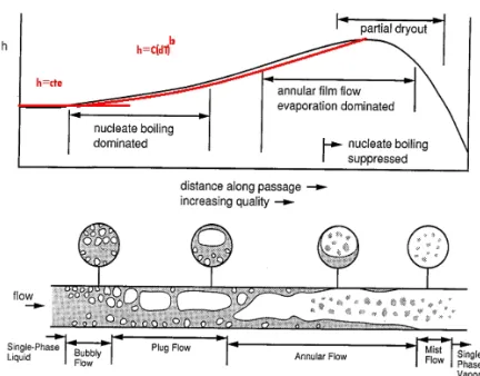
Figure 1. Heat transfer coefficient variations with flow regimes
In the next step, just solid wall model according to new heat transfer boundary conditions is solved for each node. In order to consider the effects of coolant pressure, boiling and the local temperature a correction parameter is applied. The advantage of this method is that it does not require repeating CFD calculations in cooling passages. This method is appropriate for step-by-step design that needs numerous and fast modelling. Figure 1 shows variations of heat transfer coefficient in different regimes of two-phase flow. The red curve demonstrated on this figure is curve-fitted diagram consisting of two parts:
In the situation that boiling does not happen, good approximation of convective heat transfer coefficient can be calculated according to fluid velocity, hydraulic diameter, etc., known ash . Different regimes of flow 0
boiling in water jackets cause a change in convective heat transfer coefficient, known ashQ. For calculating
total heat transfer coefficient, both these coefficients should be considered.
Q h h
h= 0+ (1)
In fact,hQ in Equation (1) is a correction term to consider influences of boiling. There are many empirical correlations available in the literature for calculation of boiling heat transfer. One of the pioneering models in this regard was first presented by Foster-zuber [13]. Foster-zuber model for water and ethylene alcohol is:
( ) 0.75
sat 24 . 1 s w 24 . 0 v 24 . 0 fg 29 . 0 5 . 0 49 . 0 l 45 . 0 P 79 . 0 1
4 T T P
h C k 10 22 . 1 q D r m s r -ú ú û ù ê ê ë é ´
= - (2)
According to Equation (2), heat transfer coefficient is equalto:
l w Q T T
q h
-= (3)
Experimental data indicate that temperature difference all over the cooling passages is not more than 7 degrees. Fluid properties are assumed constant. Equation (2) can be rewritten as:
1 L 75 . 0 sat 24 . 1 S W 1
Q C (T T ) P (Tw T )
h = - D - - (4)
By employing Foster-zuber correlation to calculate the correction term, mentioned before, Equation (1) changes to the following form:
1 L 75 . 0 sat 24 . 1 S W 1
0 C(T T ) P (Tw T )
h
h= + - D - - (5)
In this equation,Tw and TSare wall temperature and boiling temperature at 1.7bar and 130oC respectively in
C
o .
L
T is fluid mean temperature considered to be about C
3. PRINCIPAL HEAT TRANSFER COEFICIENT FORMULATION
In this work, two gasoline engines (1.8 & 1.7 liter displacement volume) water jackets have been considered to calculate convective heat transfer coefficients. It has been assumed that boiling occurs just in the second engine (1.7 liter). First, two water jacket geometric models have been meshed. For considering boiling effect in the second engine, its block (solid) and water jacket (fluid) geometric models have been coupled together and meshed entirely.
3. 1. 3D Geometry and Meshing Figure 2 shows meshing of 3D geometry of water jacket of the engine. This geometric model has been meshed by means of Hyper-mesh. The quadrilateral elements have been selected for meshing.
In order to reduce errors and speed up solution, the size and number of the elements were optimized. The criteria of surface and volume factor are 4 and 5 receptively, although in the present work these factors are less than 2.1 and 3.8. The element length has been considered less than 2.5mm. Three boundary conditions as following have been determined for the model in the Hyper-mesh software:
1- Inlet: Mass flow rate is equal to 150 lit/min (at 6000rpm engine speed)
2- Outlet: outlet pressure is equal to 1atm.
3- Non-slip condition (All regions except for the input and output area)
3. 2. Jacket Heat Transfer without Boiling Effect 3-D geometric models of cooling passages have been solved by CFD software separately.The numerical method employed for discretizing the governing equations is the control volume. The simple algorithm has been followed for handling the pressure velocity coupling. The quick method employed for discretizing the momentum and energy equations.
While the first order upwind method employed for discretizing the turbulent kinetic energy equation as well as turbulent dissipation rate equation. Solutions have done at constant temperature conditions prior to the boiling temperature. As mentioned before, the flow through the Water jacket of 1800cc engine has been analyzed without considering boiling phenomenon.
Results demonstrate the distribution of heat transfer coefficient in this engine. Due to high velocity of coolant at the inlet and outlet, convective coefficient seems larger in these zones. According to these results, fluid velocity considerably influences the heat transfer coefficient. These results have a good accuracy when there is no boiling regime throughout the water jacket. When the engine operates in full load condition, some
regions in the cooling passages of cylinder head experience boiling phenomenon.
3. 3. Water Jacket Heat Transfer with Boiling Effect As previously mentioned, when the engine is in full load condition, boiling effects within water jacket is inevitable. Therefore, in this section in order to simulate the real condition of the coolant, the boiling phenomenon will be considered.
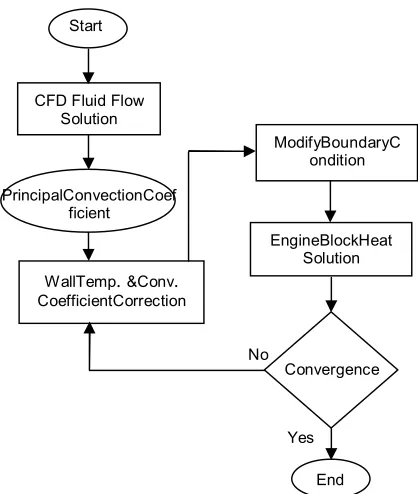
To consider the boiling effect in calculating convective heat transfer coefficient, Equation (5) has been applied. In fact, by means of this equation, the convective coefficient is corrected. Figure 3 shows the employed algorithm for calculation of heat transfer and thermal stress.
Figures 4, 5 and 6 shows the results of the CFD code analysis for second engine. The results are based on two-phase model and satisfy their experimental data. Mean convective coefficient obtained by present work is 6180W m2K. Results reveal that using the proposed model has high computational speed and the accuracy of this solution will be evaluated in next section.
Figure 2. Water jacket geometry after meshing front view
Figure 3. Heat transfer and thermal stress calculating algorithm
CFD Fluid Flow Solution
WallTemp. &Conv.
CoefficientCorrection
EngineBlockHeat Solution ModifyBoundaryC
ondition
No
Yes Start
End Convergence PrincipalConvectionCoef
At the end of this stage, principal heat transfer coefficient data is stored in a file. After that, temperature and convection coefficient is corrected by correlation 5 for each node. These data can be used in thermal stress analysis on engine walls and does not need more CFD solution. But, in coupling method it is necessary to repeatedly perform the CFD solution. It means that much time is needed to solve the problem because the fluid flow governing the equations (1 continuum, 3 momentums, 2 turbulences, 1 energy and 1 concentration) are nonlinear.Figure 7 shows the vapor quality of coolant within water jackets by considering boiling phenomenon. Present results show that in full load condition temperature of engine block and cylinder head is higher than the boiling temperature of thecoolant. Then, there is Sub-cooled boiling regime in all area of the water jacket and bubbles are formed in the mentioned area. Bubbles within the relatively high flow velocity (block water jacket) are condensed and disappear, but in the areas with low flow velocity the bubbles cannot move (cylinder head water jacket and near the gasket). In the cylinder head, despite high flow velocity, vapor quality is considerable in comparison with block passages because the temperature of the cylinder head surface is higher than that of the block. Figure 7 also shows that vapor quality of passages near the gasket is higher than those of the block and cylinder head. This is due to inadequate flow velocity and also its regime in that area. Flow regime in this area has too slow and there is circulation before and after cylinder head gasket.
Figure 8 shows cross section of block and cylinder head gasket interface. According to Figures 7 and 8 vapor quality is increased both sides of the gasket area. High vapor quality near the mentioned cross section reveals that thermal stress on the gasket is critical. In order to avoid critical conditions and vaporz accumulation in this region, the gasket area should be minimized in design phase.
4. VALIDATION
4. 1. Grid Independence Mesh independency is one of the important steps of model verification. The best parameter as a criterion for judgment is the mean heat transfer coefficient. Variation of the heat transfer coefficient against different applied mesh numbers is
figure, increasing number of cells to more than 1 million does not cause any considerable alteration in the results. However, the results obtained with this number of meshes are acceptable.
To enhance the performance of the cell number, elements' size varies for different passages area. According to Figure 2 elements' size in cylinder head specially near exhaust port are smaller than other area.
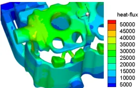
Figure 4. Convective heat transfer coefficient variation in cooling passages
Figure 5. Convective heat transfer coefficient variation in cylinder head gasket
Figure 6. Convective heat transfer coefficient variation in outlet area
Figure 7.Vapour quality variations within cooling passages
Figure 8. Cross section of block and cylinder head gasket interface
Gasketarea Gasket hole
(fluid flow)
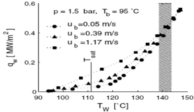
4. 2. Validation of the Boiling Modeling In order to evaluate the accuracy of this method, results of current study have been compared with experimental results of literature [12]. Geometry employed in both studies are similar.
The test case is schematically shown in Figures 10 and 11. To use equal operating conditions, the same hydraulic diameters as what applied in Ref. Karamangil et al. [12] are considered for the test device and engine water jacket. There are possibilities in the test to measure heat transfer before and after boiling occurs. Figure 12 shows the test results.
Figure 13 shows the geometry and its elements. Comparison of simulation data with the test results and the accuracy of the method are shown in Figure 14. As can be seen, at fluid velocities close to the average velocity of coolant fluid in engine, the convective coefficient will predict with accuracy about 20%.
Figure 9. Variation of heat transfer coefficient against number of meshes (mesh independency representation)
Figure 10. Test bench [12]
Figure 11. Test bench schematic
Figure 12. Experimental results,Tinlet =95oC& P=1.5bar
Figure 13. Geometry of test area
Figure 14. Variations of wall heat transfer with wall temperature, Tinlet =95oC, P=1.5bar &Ub=1.17m/s
4. 3. Validation of the Present Method In previous section the boiling modelling validation in rectangularcross section channel similar to engine cooling passageshas been discussed. Now, the results of whole engine water jacket is compare with experimental data that have done on test bench.
outlet temperature was set to 110°C. The temperature increase in engine (ΔT) is the appropriate parameter to compare the simulation and test results. ΔT is calculated from the difference between temperature downstream water of the pump minus that of the upstream of thermostat. Figure 15 shows the variations of temperature increase in engine for full load condition and speed variations. According to this figure there is a relatively good agreement with test and simulation data. The error in simulation data is related to the boiling phenomenon. For low speed conditions, the temperature difference of coolant is high because mass flow rate under these conditions is less than the high speed condition. As previously mentioned, coolant outlet temperature set to 110 °C therefore its inlet temperature for low speed will be lower than that for high speed. It means that when the engine speed in full load condition increases, the water jacket mean (bulk) temperature increase too, then the area with boiling phenomenon will increase. The more area with boiling phenomenon, the more error results.
5. SUMMARY AND RESULTS
As previously denoted, the refrigerant flowing in cooling passages of a gasoline engine operating in full load condition, will inevitably boil. Undersuch conditions, ignoring boiling influences especially in heat calculations as well as design procedure, may result in considerable calculation error.
In this study, the principal convection heat transfer coefficient method has been presented and employed to model boiling heat transfer in cooling passages of a typical gasoline engine. The model is then evaluated using experimental results with similar geometry as employed in this study. Maximum deviation of 20% is observed in this comparison. In the present work, data extracted from engine functional test has been used to validate the boiling simulation in engine cooling passage. Trend of simulated data in predicting engine coolant inlet and outlet temperature differences shows that the proposed method is reliable and practical. The following results have been achieved:
Figure 15. Variations of engine ΔT for full load condition and speed variation
When boiling occurs, the heat transfer coefficient on the critical points considerably increases.
- Around the gasket hole, the bubbles accumulate and vapor quality increases considerably. In order to avoid critical conditions in this region, the gasket area should be minimized in design phase.
- The proper flow velocity within the cylinder head water jacket can be determined in order to condensate and move the bubbles.
- In present method coolant temperature distribution of engine cooling passage can be calculated.
- The innovative method proposed in this study significantly increases computation rate and due to its acceptable precision, it can be an appropriate applicable approach for detailed design procedure without engine functional test. Hence, design phase is shortened considerably.
6. REFERENCES
1. Kandlikar, S.G., "Heat transfer mechanisms during flow boiling in microchannels", in ASME 1st International Conference on Microchannels and Minichannels, American Society of Mechanical Engineers, (2003), 33-46.
2. Khameneh P. M., Mirzaie I., Pourmahmoud N., Majidyfar S., Azizi S.H. and Andalibi M. R., "A numerical study of single-phase forced convective heat transfer with flow friction in microchannels", International Journal of Engineering, Vol. 25, No. 1, (2012), 79-88.
3. Kim, D., Kim, S.J. and Ortega, A., "Compact modeling of fluid flow and heat transfer in pin fin heat sinks", Journal of Electronic Packaging, Vol. 126, No. 3, (2004), 342-350. 4. Chen, L., Tian, Y. and Karayiannis, T., "The effect of tube
diameter on vertical two-phase flow regimes in small tubes",
International Journal of Heat and Mass Transfer, Vol. 49, No. 21, (2006), 4220-4230.
5. Lee, P.C. and Pan, C., "Boiling heat transfer and two-phase flow of water in a single shallow microchannel with a uniform or diverging cross section", Journal of Micromechanics and Microengineering, Vol. 18, No. 2, (2008).
6. Alavi, F.S. and Seyf, K.A., "Pool boiling heat transfer in water/amines solutions", International Journal of Engineering, Vol. 21, No. 2, (2008), 113-131.
7. Mehta, J.S. and Kandlikar, S.G., "Pool boiling heat transfer enhancement over cylindrical tubes with water at atmospheric pressure, part ii: Experimental results and bubble dynamics for circumferential v-groove and axial rectangular open microchannels", International Journal of Heat and Mass Transfer, Vol. 64, (2013), 1216-1225.
8. Heywood, J.B., "Internal combustion engine fundamentals, McGraw-Hill New York, Vol. 930, (1988).
9. Robinson, K., Hawley, J. and Campbell, N., "Experimental and modelling aspects of flow boiling heat transfer for application to internal combustion engines", Proceedings of the Institution of Mechanical Engineers, Part D: Journal of Automobile Engineering, Vol. 217, No. 10, (2003), 877-889.
11. Ho Sung L. and Cholewczynski L. W., "A study on convection and boiling heat-transfer modes in a standard engine cooling system", DaimlerChrysler Grant.
12. Karamangil, M., Kaynakli, O. and Surmen, A., "Parametric investigation of cylinder and jacket side convective heat transfer coefficients of gasoline engines", Energy Conversion and Management, Vol. 47, No. 6, (2006), 800-816.
13. Ajotikar, N., Eggart, B.J. and Miers, S.A., "Nucleate boiling identification and utilization for improved internal combustion engine efficiency", in ASME 2010 Internal Combustion Engine Division Fall Technical Conference, American Society of Mechanical Engineers, (2010), 949-958.
14. Punekar, H. and Das, S., "Numerical simulation of subcooled nucleate boiling in cooling jacket of IC engine",(2013), SAE Technical Paper.
Simulation of Boiling Heat Transfer within Water Jacket of 4-cylinder
Gasoline Engine
TECHNICAL NOTE
Z. Baniameriana, M. Nazoktabarb, R. Mehdipourb
aDepartment of Engineering, Islamic Azad University, Roudehen Branch, Roudehen, Iran
bDepartment of Mechanical Engineering, Tafresh University, Tafresh, Iran
P A P E R I N F O
Paper history:
Received 19 February 2014 Received in revised form 07April 2014 Accepted 14August 2014
Keywords:
Boiling Phenomenon Water Jacket Heat Transfer Boiling Heat Transfer Coefficient
هﺪﯿﮑﭼ
ﺶﻫﺎﮐﺎﺑماﻮﺗرﻮﺗﻮﻣﻪﻨﯿﻬﺑﯽﺣاﺮﻃهزوﺮﻣا
اﺪﻧا زه
ﺖﺳانآ
.
هﺎﮕﻫارﻢﺠﺣﺶﻫﺎﮐﻖﯾﺮﻃزارﻮﺗﻮﻣدﺎﻌﺑاﺶﻫﺎﮐﺮﺿﺎﺣرﺎﮐزافﺪﻫ
بآ رﻮﺗﺎﯾدار
ﯽﻣنآردتراﺮﺣلﺎﻘﺘﻧاﺶﯾاﺰﻓاهاﺮﻤﻫﻪﺑ
ﺪﺷﺎﺑ
.
ﻪﺴﯾﺎﻘﻣردتراﺮﺣلﺎﻘﺘﻧاﻪﺟﻮﺗﻞﺑﺎﻗﺶﯾاﺰﻓاﺎﺑﺶﺷﻮﺟهﺪﯾﺪﭘ
ﺎﺑ
ﯽﻣﻢﻫاﺮﻓار هﺎﮕﻫار ﻢﺠﺣ ﺶﻫﺎﮐنﺎﮑﻣا،زﺎﻓ ﮏﺗﯽﯾﺎﺠﺑﺎﺟ تراﺮﺣلﺎﻘﺘﻧا
دزﺎﺳ
.
هﺎﮕﻫارردﺶﺷﻮﺟ هﺪﯾﺪﭘﻪﻟﺎﻘﻣ ﻦﯾارد
ﮏﻨﺧ يرﺎﮐ يﺎﻫرﻮﺗﻮﻣ ﯽﻨﯾﺰﻨﺑ ﻪﯿﺒﺷ يزﺎﺳ
ﺖﺳاهﺪﺷﻦﯿﯿﻌﺗﺶﺷﻮﺟعوﺮﺷﻪﻄﻘﻧو
.
ﻪﺒﺳﺎﺤﻣياﺮﺑﺪﯾﺪﺟﻪﻄﺑارﮏﯾلﺪﻣﻦﯾارد
ﺖﺳاهﺪﺷﻪﺋارازﺎﻓودنﺎﯾﺮﺟردتراﺮﺣلﺎﻘﺘﻧاﺐﯾﺮﺿ
.
هﺪﺷﻪﺴﯾﺎﻘﻣﯽﻫﺎﮕﺸﯾﺎﻣزآيﺎﻫهدادﺎﺑﺲﭙﺳهﺪﺷﻪﺋارالﺪﻣﺞﯾﺎﺘﻧ
ﺪﻧا
.
ﯽﻣنﺎﺸﻧﺞﯾﺎﺘﻧ
ﺪﻨﻫد ﻪﮐ
ﯽﻣوهدﻮﺑرادرﻮﺧﺮﺑﯽﺑﻮﺧﺖﻗدزاهﺪﺷﻪﯾارالﺪﻣ
دﻮﻤﻧهدﺎﻔﺘﺳانآزارﻮﺗﻮﻣﯽﺣاﺮﻃﻞﺣاﺮﻣردناﻮﺗ
.