Improved Direct Torque Control for Induction Machine
Drives Based on Fuzzy Sector Theory
M. M. Rezaei* and M. Mirsalim**
Abstract: Here, a new fuzzy direct torque control algorithm for induction motors is
proposed. As in the classical direct torque control, the inverter gate control signals directly come from the optimum switching voltage vector look-up table, the best voltage space vector selection is a key factor to obtain minimum torque and flux ripples. In the proposed approach, the best voltage space vector is selected using a new fuzzy method. A simulation model is built up and the torque and flux ripples of basic direct torque control and the proposed method are compared. The simulation results show that the torque and flux ripples are significantly decreased and in addition, the switching frequency can be fixed.
Keywords: Direct Torque Control, Fuzzy Logic, Induction Machine.
1 Introduction1
Since direct torque control (DTC) of induction motors was proposed in the middle of 1980's [1-2], more than two decades has passed. The basic idea of DTC is slip control, which is based on the special relationship between the slip frequency and electromagnetic torque. The most common way to carry out the DTC is to use switching table and hystersis controller, as reported in [2-5]. Fig.1 shows the diagram for a DTC induction machine (IM) drive system. It includes flux and torque estimators, flux and torque hystersis controller and a switching table. The switching state of the inverter is updated in each sampling interval.
Although DTC is getting more popular, it also has some drawbacks, such as the torque and flux ripples [4]. In this case, none of the inverter switching vectors is able to generate the exact stator voltage required to produce the desired changes in the electromagnetic torque and stator flux linkages in most of switching instances. This undesirable ripple is of higher value when the selected state of the inverter remains unchanged for several sampling periods and especially when the stator flux linkage space vector (FLSV) is
Iranian Journal of Electrical & Electronic Engineering, 2010. Paper first received 10 Oct. 2009 and in revised form 17 Jan. 2010. * The Author is with the Department of Electrical Engineering, Amirkabir University of Technology (Tehran Polytechnic), Center of Excellence in Power Systems, Tehran 15914, Iran.
E-mail: [email protected]
** The Author is with the Department of Electrical Engineering, Amirkabir University of Technology (Tehran Polytechnic), Center of Excellence in Power Systems, Tehran 15914, Iran.
E-mail: [email protected]
moving from one sector to the neighbour sectors. However, using various techniques can be reduced the ripples in the electromagnetic torque and stator flux. Some of these techniques involve the usage of high switching frequencies [6-7] or the change in inverter topology [8-9]. However, an increment of switching frequency will increase the switching losses and semiconductor devices of inverter. Furthermore, in case of high switching frequency, a fast processor is required since the control processing time becomes small. In addition, the change in inverter topology leads to use an increased number of switches.
In this paper a new direct torque controlled IM drive algorithm based on fuzzy logic is proposed to improve the performance of the drive in terms of ripple reduction. Particle swarm optimization (PSO) is also used to tune off-line PI speed controller parameters [10]. The paper is organized as follows. Section 2 briefly introduces the DTC principle. The structure of the proposed fuzzy-DTC scheme is presented in section 3. In section 4, a Matlab/Simulink model is built to test the algorithm. Then, steady state and dynamic responses are compared with basic DTC. The conclusions are drawn in section 5.
2 Direct Torque Control
A general block diagram of DTC scheme is shown in Fig. 1. In this system, the instantaneous values of flux and torque are calculated from stator variables. The stator flux linkage space vector can be obtained from measured currents and voltages according to stator voltage equation of an IM in the stationary reference frame and rewritten as [4]:
( )
s us R i dts s
ψ =
∫
− (1)where ψs ,us,is ,Rs are the stator flux linkage vector,
voltage vector, current vector and resistant respectively. Electromagnetic torque can be calculated from estimated flux linkages and measured stator currents as expressed in (3).
( )
( )
sD sD s sD
sQ sQ s sQ
u R i dt
u R i dt
ψ
ψ
= −
= −
∫
∫
(2)3
2 ( )
e sD sQ sQ sD
T = p
ψ
i −ψ
i (3)where ψsD,ψsQ,vsD,vsQ,isD,isQ are stator flux
linkages, voltages and currents in d-q coordinates respectively.
Stator flux and torque can be controlled directly and independently by properly selecting the inverter switching configurations. If for simplicity it is assumed that the stator ohmic drop can be neglected, then
s s
dψ dt =u . It can be seen that the inverter voltage directly impresses the stator flux, and therefore in a short
t
Δ time, when the voltage vector is applied, one can assume that:
s us t
ψ
Δ ≈ Δ (4)
Thus, the stator FLSV moves by Δψs in the direction of stator voltage space vector at a speed that is proportional to the magnitude of the stator voltage space vector. Decoupled control of the torque and stator flux is achieved by acting on the radial and tangential components of the stator FLSV in the locus. These two components are directly proportional to the components of the stator space vector in the same direction, and thus the appropriate inverter switching can control them.
In a six steps voltage source inverter (VSI), eight switching combinations can be selected; two of which determine zero voltage vectors and the remaining generate six equally spaced voltage vectors,
1 2 6
( ,u u ,...,u ) having the same magnitude, as expressed in equation (5).
2
3 exp[ ( 1) 3], 1, 2,...,6.
s k d
u u U j k
k
π
= = −
= (5)
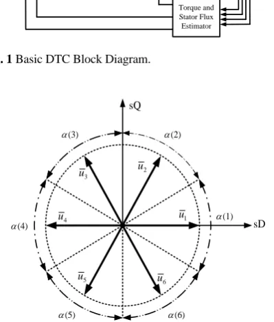
where, Ud is the DC link voltage of the inverter. Fig. 2
illustrates six switching voltage vectors that cover six sectors, α(1), (2),..., (6)α α . According to the principle of operation of DTC, the selection of a proper voltage vector at each sampling period is made, in order to maintain the torque and the stator flux within the limits of two hysteresis comparator bands. In particular, the selection is made based on the position of the stator flux and the instantaneous errors in torque and stator flux magnitudes.
Assume that the stator flux vector is in kth sector of the d-q plane, where k =1,2,…,6. The flux magnitude can be increased by selecting the voltage vectors
1 ,
k k
u u +and uk−1 as in Fig. 2. Conversely, the decrease of ψs could be obtained by selecting uk+2,uk−2and
3
k
u + . The zero-voltage vector does not substantially affect the stator flux vector, with the exception of a small flux weakening due to the voltage drop on the stator resistance. Of course, the voltage vectors utilized to control the stator flux, also affect the torque values. An increment of torque is in general obtained by selecting the voltage vectors uk+1 and uk+2. Conversely, a
decrement of torque could be achieved by utilizing uk−1
and uk−2or the zero voltage vectors u u0, 7. In general, if
an increase (decrease) in torque is desired, then the voltage vectors that advance (retard) the flux linkage space vector in the direction (opposite direction) of rotation are applied.
The hysteresis band comparator technique, applied to control both the stator flux and torque, leads to several possible conditions with reference to the instantaneous errors. Any voltage vector selection strategy for DTC scheme is aimed to find the most appropriate voltage vector that allows a decrease in torque and flux errors. It is then possible to drive stator flux and torque to follow any desired track curve. This allows the decoupled control of flux and torque to be achieved. Table 1, shows the voltage vector selection according to stator flux and torque errors.
IM
Torque and Stator Flux Estimator
VSI
Optimal Switching Voltage Vector Look-up Table
e T eref T
+ −
) (n
α +
−
s
ψ
Flux Hysteresis Comparator Torque Hysteresis
Comparator
sref
ψ
Fig. 1 Basic DTC Block Diagram.
sQ
sD
1
u
2
u
3
u
4
u
5
u
6
u
(3)
α α(2)
(1)
α
(6)
α
(5)
α
(4)
α
Fig. 2 Inverter Output Voltage Space Vectors.
3 The Torque and Flux Ripples
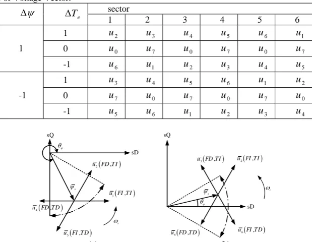
Let’s assume that the stator flux linkage space vector lays in 6th sector and rotating counter clockwise. As depicted in Fig. 3 (a), if a flux linkage increment with a simultaneous increment in torque (FI,TI) is desired, then the required optimum switching voltage vector that should be applied to the stator is u1. In Fig. 3, ψs, the
stator FLSV, is shown; where θψ is the stator flux angle, the angle between the direct axes of stator, sD and the stator FLSV.
Each voltage space vector that applied to the stator can be divided to two component, torque maker and flux maker component.
sin
T i
u =u θψ (6)
cos
i
uψ =u θψ (7)
where ui , uT and uψ are applied voltage vector, torque maker and flux maker components of the applied voltage vector. Accordingly, the torque maker and flux maker components of the applied voltage vector are functions
of the stator flux linkage space vector angle θψ. For example, while the stator flux linkage space vector lays in 6th sector and the torque and flux commands don’t have been changed, the required optimum switching voltage vector will be remained u1. In this situation, at
the beginning of the 6th sector, the flux maker component of the applied voltage vector is minimum (equal to zero) and the torque maker component of the applied voltage vector is maximum (equal to u1). As shown in Fig. 4, by increment inθψ, the torque maker and flux maker components of the applied voltage vector will be decreased and increased respectively. At the end of the 6th sector, the flux maker component of the applied voltage vector is maximum (equal to 1
1
2u ) and the torque
maker component of the applied voltage vector is minimum (equal to 1
3 2u ).
Table 1 Selection Table of Voltage Vector.
sector ψ
Δ ΔTe
1 2 3 4 5 6
1 u2 u3 u4 u5 u6 u1
0 u0 u7 u0 u7 u0 u7
1
-1 u6 u1 u2 u3 u4 u5
1 u3 u4 u5 u6 u1 u2
0 u7 u0 u7 u0 u7 u0
-1
-1 u5 u6 u1 u2 u3 u4
( )
2 ,
u FD TI
( )
5 ,
u FI TD
( )
4 ,
u FD TD
( )
1 ,
u FI TI
s
ψ
r
ω
ψ
θ sQ
sD sQ
sD
s
ψ ωr
( )
2 ,
u FI TI
( )
3 ,
u FD TI
( )
5 ,
u FD TD u FI TD6( , )
ψ
θ
(a) (b)
Fig. 3 Optimum Switching Voltage Vectors for Stator Flux Space Vector (a) in 6th Sector, (b) in 1st Sector.
sQ
sD
1
u
s
ψ 76 − o
T
u
uψ
42
− o
s
ψ
sector 6
T
u
uψ
sQ
sD
1
u
(a) (b)
Fig. 4 Torque Maker And Flux Maker Components Of The Voltage Vector u1 in Sector 6.
sQ
sD
s
ψ
s
ψ
r
ω
( )
2 ,
u FI TI
( )
1 ,
u FI TI
sector 6 sector 1
Fig. 5. Optimum Switching Voltage Vectors for Flux and
Torque Increment in 6th and 1st Sector.
Fuzzy Rule Base
Fuzzy Inference Engine
Fuzzifire Defuzzifire
Fig. 7 Fundamental Structure of Fuzzy Systems.
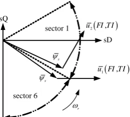
In the other hand, when the stator FLSV moves from 6th sector to 1st sector, according to optimum voltage vectors look-up table, the applied voltage vector should be altered without any change in the desired torque and flux. For example, according to Table 1, the switching vector u1 is applied for a desired torque increment and
flux increment in 6th sector, while with the arrival of the stator FLSV in 1st sector, the switching vector u2 must
be applied for the same desired conditions as depicted in Fig. 5.
Generally, when the stator FLSV moves from one sector to another, without any changes in Δψ and ΔTe,
the voltage vector that have been applied to motor will be changed as shown in Fig. 6. The applied voltage vectors changes in the end of the old sector and in the beginning of the new sector cause intense torque and stator flux variations and create the significant ripples in the electromagnetic torque and stator flux linkages. On the other hand, the so-called “best” voltage vectors in each sector, defined by look-up table, cannot really be the best for various conditions of flux and torque errors and flux space vector location. The implementation of
the above rules arise the following question: How can we decrease the torque and flux ripples? An answer to this question can be given by using the fuzzy sets.
4 Fuzzy Logic
Fuzzy logic is able to use human reasoning not in terms of discrete symbols and numbers, but in terms of fuzzy sets. These terms are quite flexible with respect to the definition and values. From the idea of elastic sets, the concept of a fuzzy set has been proposed. Fuzzy sets are functions that map a value that might be a member of the set to a number between zero and one indicating its actual degree of membership. A degree of zero means that the value is not in the set and a degree of one means that the value is completely representative of the set. This produces a curve across the members of the set [7]-[9].
As it is depicted in Fig. 7, a fuzzy controller generally consists of four subsystems, in which two parts have the duty of transformation: fuzzifier (first transformation), fuzzy rule base, inference engine and defuzzifier (second transformation).
The fuzzifier changes the input variables (crisp signals) into fuzzy values. The fuzzy rule base consists of basic data and linguistic rules. The inference engine is the brain of a fuzzy controller, which has the ability to simulate the human decision based on fuzzy idea. Finally, the second transformation converts the fuzzy values into the real values.
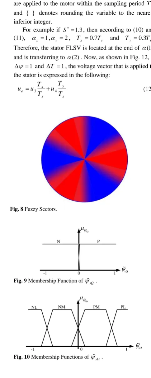
4.1 Proposed Fuzzy DTC Scheme
In this new method, the membership function of the stator flux space vector in each sector is not crisp, but also is fuzzy. So, stator flux space vector’s membership degree is fuzzy and between [0,1] in each sector. In Fig. 8, the fuzzy and the crisp sectors are shown. By implementation of this technique, the demand voltage space vector can be composed of two active voltage vectors, which described in next part. Furthermore, any variation in applied voltage vector, in consequence of the stator FLSV's sector alteration, does not be discrete. This method decreases the stator flux and torque ripples significantly.
-90 -80 -70 -60 -50 -40 -30 -1.5
-1 -0.5 0 0.5 1 1.5
Angle (degree)
Tor
qu
e
m
a
k
e
r
c
o
m
pon
e
n
t (p
u)
u1T u2T u4T u5T
-90 -80 -70 -60 -50 -40 -30 -1.5
-1 -0.5 0 0.5 1 1.5
Angle (degree)
F
lu
x
m
aker
co
m
p
o
n
en
t
(p
u
) u1ψ u2ψ u4ψ u5ψ
-90 -70 -50 -30 -10 10 30 0
0.5 1 1.5
Angle (degree)
T
o
rq
u
e an
d
f
lu
x
m
aker
co
m
p
o
n
en
ts
(
p
u
)
Torque maker component of applied voltage Flux maker component of applied voltage
(a) (b) (c)
Fig. 6 (a) Torque Maker Component of Applied Voltage Vectors in the 6th Sector, (b) Flux Maker Component of Applied Voltage
Vectors in the 6th Sector, (c) Flux and Torque Maker Components Curves in the 6th and 1st Sectors When TI and FI Is Desired.
4.2 Fuzzification
The fuzzification is the process of mapping from estimated input to the corresponding fuzzy set in the input universe of discourse. The proposed fuzzy controller has two inputs that are defined as (8):
2 2
2 2
(
(
sD sD sD sQ
sQ sQ sD sQ
ψ ψ ψ ψ
ψ ψ ψ ψ
= +
= +
%
% (8)
where ψ%sD and ψ%sQ are the normalized stator flux
linkage components in the d-q coordinates [4].
The fuzzification is performed using membership function with singleton fuzzifier. With regard to the two input variables, there are two groups of membership functions as depicted in Fig. 9-10. In these figures,
sQ
ψ
μ ,
sD
ψ
μ are membership degrees of ψ%sQ and ψ%sD
respectively.
4.3 Fuzzy Relation and Rule Bases
The fuzzy relation and fuzzy rules are defined as sets of IF-THEN rules for fuzzy inference. Control rules are often expressed in the IF-THEN format as follows:
Rule 1: IF ψ%sD is PL and ψ%sQ is P THEN S is S1
Rule 2: IF ψ%sD is PM and ψ%sQ is P THEN S is S2
Rule 3: IF ψ%sD is NM and ψ%sQ is P THEN S is S3
Rule 4: IF ψ%sD is NL and ψ%sQ is P THEN S is S4
Rule 5: IF ψ%sD is NL and ψ%sQ is N THEN S is S4
Rule 6: IF ψ%sD is NM and ψ%sQ is N THEN S is S5
Rule 7: IF ψ%sD is PM and ψ%sQ is N THEN S is S6
Rule 8: IF ψ%sD is PL and ψ%sQ is N THEN S is S1
where Si is the membership function of i
th sector.
4.4 Defuzzification
Generally, after fuzzy reasoning, the output action is presented by the fuzzy sets, which must be converted into a non-fuzzy output in terms of certain defuzzification methods, such as Center of Area, Mean of Maximum, etc. In this system, the output of the fuzzy system is the membership degree of the stator flux space vector in each sector that is calculated by the centroid defuzzification method. The output function is given in equation (9).
max{min( , )} max{min( , )}
sD sQ
sD sQ
S
S ψ ψ
ψ ψ
μ μ
μ μ
∗=
∫
(9)
where S∗ is the fuzzy sector number in the range of 1 to 7. The value of S∗ determines which of two sectors that the stator flux linkage space vector is located and transferred to
(
)
{ }
mod ( 1),6
x
y x
S α
α α
∗ =
= + (10)
* *
(1 )
( )
x x s
y x s
T S T
T S T
α α
= + −
= − (11)
where αx and αy are the sector numbers that stator
FLSV is transferred between them, Tx and Ty are the
effective time intervals for the two voltage vectors that are applied to the motor within the sampling period Ts
and { } denotes rounding the variable to the nearest inferior integer.
For example if S∗=1.3, then according to (10) and (11), αx =1,αy =2, Tx =0.7Ts and Ty =0.3Ts. Therefore, the stator FLSV is located at the end of α(1)
and is transferring to α(2). Now, as shown in Fig. 12, if
1
ψ
Δ = and Δ =T 1, the voltage vector that is applied to the stator is expressed in the following:
3 4
y x
e
s s
T T
u u u
T T
= + (12)
Fig. 8 Fuzzy Sectors.
N P
0 1
-1
μψ
sQ
~
ψsQ
~
Fig. 9 Membership Function of ψ%sQ.
NM
NL PM PL
-1 ψsD
~ μψ
sD
~
0 1
Fig. 10 Membership Functions of ψ%sD.
s μs
1 2 3 4 5 6
2
s
1 3 s4 s5 s6 s
S
7
s 7
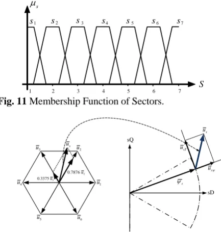
Fig. 11 Membership Function of Sectors.
Fig. 12 Selection of Voltage Vectors According to the Flux
Linkage Vector’s Fuzzy Sector.
5 Simulation Results and Comparisons
Two Matlab/Simulink models have been developed to examine the different control algorithms one for the basic of DTC, and the other for the modified DTC. The parameters of the induction motor have been shown in Table 2. As mentioned before, PSO is used to tune the PI controller coefficients [10]. A DTC control model based on PSO-PI is shown in Fig. 13. In this figure,
ω
∗ is system input (the reference speed),T
∗is the output of PI controller, which used to control the torque of DTC andω
is system output (the rotor speed).The PSO algorithm was mainly utilized to determine two optimal PI controller parameters(KP,KI), such that the controlled system could obtain a good step response output [10]. The tuned PI coefficients can be found in Table 3.
Flux and torque maker components in the 6th and 1st sectors under the modified DTC have been shown in Fig. 14. Compared with Fig. 6 (c), the intense ripple of the flux and torque maker component, shown in Fig.14 has been significantly decreased.
The stator flux linkage and the sector numbers that FLSV located in, under the conventional DTC, have been shown in Figs. 15 (a-b).
As depicted in this figure, while flux linkage increment with a simultaneous torque increment (FI,TI) is desired, according to Fig. 6, when the FLSV is located in the beginning of each sector, the flux maker component is low and thus the magnitude of stator flux linkage cannot be increased whereupon, the intense flux ripple will be inevitable.
In the proposed method, the sector number that
FLSV located in is fuzzy value and thus the voltage space vector applied to stator can be assumed as a fuzzy vector. Thus, the variation of flux maker component of applied voltages will be reduced, as confirmed in Fig. 14. Thus, the stator flux linkage ripple will be reduced significantly. In Figs. 15 (c-d), the stator flux linkage and the fuzzy sector numbers that FLSV located in, under the modified DTC have been shown.
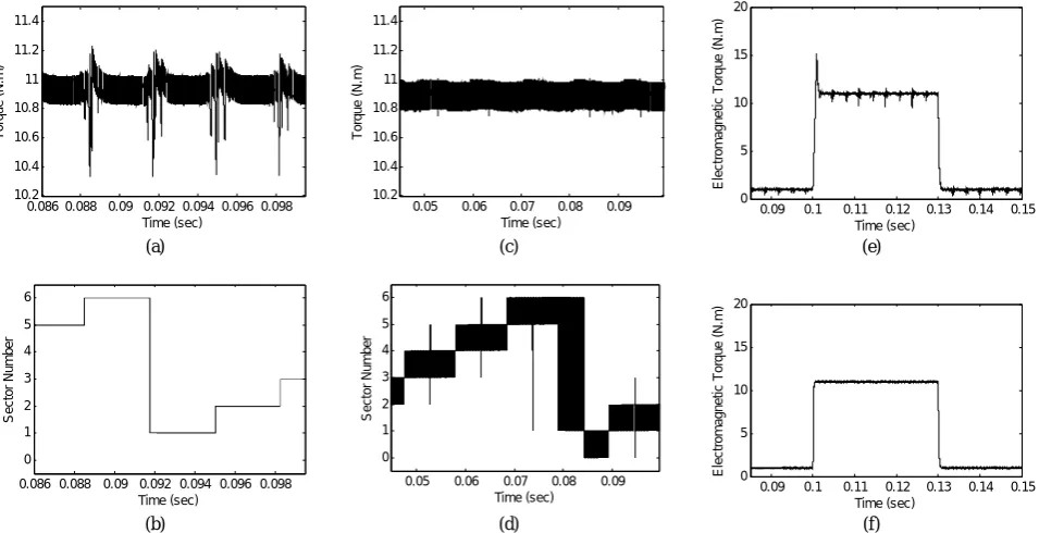
The electromagnetic torque and the sector number that FLSV located in, under the conventional and modified DTC, have been shown in Fig. 16. As depicted in Fig. 6, when the FLSV is located in the beginning or in the ending of each sector, one of the torque maker component or flux maker component is low certainly.
Accordingly, the electromagnetic torque cannot be increased or decreased properly, as depicted in Fig. 16 (a-b). Thus, the intense torque ripple will be inevitable. However, in Figs. 16 (c-d) the torque maker component variation of applied voltages will be reduced and the electromagnetic torque ripple will be consequently reduced. As depicted in Figs. 16 (e-f), The electro-magnetic torque ripple under the modified DTC is very lower than under the conventional DTC (until 50%).
It may be deduced that the switching frequency of the modified DTC is very higher than conventional DTC. However, the comparison between above figures cannot be authentic evidence; because of the switching frequency of conventional DTC in the start process, is low. As mentioned earlier, owing to oscillation of the magnitude of the flux and torque maker components of applied voltage under the conventional DTC, the switching states of the inverter stay constant for a long time especially in the start process. Therefore, the switching frequency will be reduced and according to nominal switching frequency (when the DTC drive will be in nominal states); the maximum switching capability of the devices cannot be fully utilized.
PSO-PI DTC
+
− M
∗
ω ω
eω
SPEED SENSOR
T∗
Fig. 13 DTC control model based on PSO-PI.
-90 -70 -50 -30 -10 20 30
0 0.5 1 1.5
Angle (Degree)
T
o
rq
u
e
a
n
d
f
lu
x
m
aker
co
m
p
o
n
e
n
ts
(
p
u
)
Torque maker component of applied voltage Flux maker component of applied voltage
Fig. 14 Flux and Torque Maker Components in the 6th and 1st
Sectors under the Modified DTC.
sQ
sD
s
ψ
s
u
2
u
3
u
5
u u6
1
u
4
u
s
u
ψ s
u
sT
u
2
7876 .
0 u
3
3375 .
0 u
0.01 0.012 0.014 0.016 0.018 0.02 0.77 0.78 0.79 0.8 0.81 0.82 Time (sec) S tat or F lux ( w b )
0.01 0.012 0.014 0.016 0.018 0.02
0.77 0.78 0.79 0.8 0.81 0.82 Time (sec) S tat or F lux ( w b )
0 0.02 0.04 0.06
0.74 0.76 0.78 0.8 0.82 0.84 Time (sec) S tat or F lux ( w b)
(a) (c) (e)
0.01 0.012 0.014 0.016 0.018 0.02
0 1 2 3 4 5 6 Time (sec) Se c to r N u mb e r
0.01 0.012 0.014 0.016 0.018 0.02
0 1 2 3 4 5 6 Time (sec) Se c to r N u mb e r
0 0.02 0.04 0.06
0.74 0.76 0.78 0.8 0.82 0.84 Time (sec) S tat or F lu x (wb )
(b) (d) (f)
Fig. 15 (a) Stator Flux Linkage, (b) Sector Number that Stator FLSV Located in, both under the Conventional DTC; (c) Stator Flux
Linkage, (d) Sector Number that Stator FLSV Located in, both under the Modified DTC; (e-f) Stator Flux Linkage under the Conventional and Modified DTC Respectively.
0.086 0.088 0.09 0.092 0.094 0.096 0.098 10.2 10.4 10.6 10.8 11 11.2 11.4 Time (sec) T o rqu e (N. m )
0.05 0.06 0.07 0.08 0.09
10.2 10.4 10.6 10.8 11 11.2 11.4 Time (sec) T o rqu e (N. m )
0.09 0.1 0.11 0.12 0.13 0.14 0.15
0 5 10 15 20 Time (sec) E lec tr om ag ne ti c T o rq ue (N .m )
(a) (c) (e)
0.086 0.088 0.09 0.092 0.094 0.096 0.098
0 1 2 3 4 5 6 Time (sec) Se c to r N u mb e r
0.05 0.06 0.07 0.08 0.09
0 1 2 3 4 5 6 Time (sec) S e c tor N u m ber
0.09 0.1 0.11 0.12 0.13 0.14 0.15
0 15 10 5 20 Time (sec) E lec tr om ag ne ti c T o rq ue (N .m )
(b) (d) (f)
Fig. 16 (a) Electromagnetic Torque, (b) Sector Number that Stator FLSV Located in, both under the Conventional DTC; (c)
Electromagnetic Torque, (d) Sector Number that Stator FLSV Located in, both under the Modified DTC; (e-f) Electromagnetic Torque Step Response under the Conventional and Modified DTC Respectively.
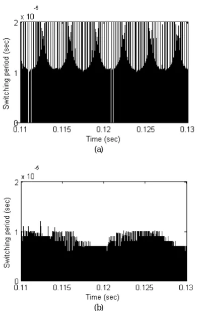
The switching period under conventional and modified DTC has been shown in Fig. 17. As depicted in this figure, although the minimum switching period under the modified DTC is thinly higher than under the conventional DTC, the changing switching frequency
under the modified DTC is very lower than under the conventional DTC.
6 Conclusions
In order to performance improvement of the direct torque control drive for induction motor and to reduce
the ripples in torques and flux linkages, a novel fuzzy logic based DTC has been proposed. The PI speed controller has been off-line tuned using PSO. As a result, both torque and flux linkage ripples are significantly reduced, and aside from negligible switching frequency increment, the switching frequency variation decreased. The simulation results show the performance of the new proposed control strategy.
(a)
(b)
Fig. 17 Switching Period (a) under the Conventional DTC, (b)
under the Modified DTC.
Table 2 Parameters of the Induction Machine.
5 Rated output power (kWatt)
460 Rated Voltage (Volt)
60 Rated frequency (Hz)
1 Pole pairs
1750 Rated speed (rpm)
1.115 Stator resistance (ohm)
1.083 Rotor resistance (ohm)
203.7 Main inductance (mH)
5.974 Stator leakage inductance (mH)
5.974 Rotor leakage resistance (mH)
0.02 Inertia (Kg.m2)
Table 3 The Tuned PI Controller Coefficients.
152.8513 Proportional Gain
1.5534 Integral Gain
References
[1] Depenhrock M., “Direct Self-Control of Inverter-Fed Machine”, IEEE Trans. Power Elec., Vol. 3, No.4, pp 420-429, Oct. 1988.
[2] Naguchi T. and Takahashi I., “A New Quick-Response and High Efficiency Control Strategy of an Induction Motor”, IEEE Trans. Ind. App., Vol. IA-22, pp. 820-827, Sept./Oct. 1986.
[3] Casadei G., Serra D. and Tani A., “Implementation of A Direct Torque Control Algorithm for Induction Motors Based on Discrete Space Vector Modulation”, IEEE Trans. Power Elec., Vol. 15, No. 4, pp. 769-777, July 2000.
[4] Vas P., Sensorless Vector and Direct Torque Control, Oxford University Press, 1998.
[5] Lascu C., Boldea I. and Blaabjerg F., “A Modified Direct Torque Control for Induction Motor Sensorless Drive”, IEEE Trans. Ind. App., Vol. 36, No.1, pp. 122-130, Jan/Feb 2000.
[6] Gholizad H. and Mirsalim M., “A New Method for the Reduction of Flux and Torque Ripples in DTC”, ICEE01 Conf., May 8-10, 2001.
[7] Zhang J., Rahman M. F. and Grantham C., “A New Scheme to Direct Torque Control of Interior Permanent Magnet Synchronous Machine Drive for Constant Inverter Switching Frequency and Low Torque Ripple”, IPEMC IEEE Conference, 2006.
[8] Quinder K.E.B., Ruppert F. and Milton E., “A Three-Level Inverter Direct Torque Control of a Permanent Magnet Synchronous Motor”, IEEE ISIE06, pp. 2361-2366, Quebec, Canada, July 9-12, 2006.
[9] Garcia X., Arias A., Jayne M., Witting P., Sala V. and Romeral J., “New DTC Control Scheme for Induction Motors fed with a Three-level Inverter”, AUTOMATIKA 46, pp. 73–81, 2005. [10] Cao C., Zhou B., Li M. and Du J., “Digital
Implementation of DTC Based on PSO for Induction Motors”, 6th World Congress on Intelligent Control and Automation, Dalian, China, June 2006.
Mohammad Mahdi Rezaei was born in
Isfahan, Iran, on September 26 1982. He received B.S. degree in electrical engineering from the Islamic Azad University (Top student among more than 180 people), Isfahan, Iran in 2004 and M.S. degree in electrical engineering from Amirkabir University of Technology (Tehran Polytechnic) on 2007. His research interests cover many aspects of power engineering including design, optimization and implementation of electrical drives, design and implementation of magnetic devices, power system voltage stability improvement, optimized load shedding.
Mojtaba Mirsalim (IEEE Senior Member' 2004) was born in Tehran, Iran, on February 14, 1956. He received his B.S. degree in EECS/NE, M.S. degree in Nuclear Engineering from the University of California, Berkeley in 1978 and 1980 respectively, and the Ph.D. in Electrical Engineering from Oregon State University, Corvallis in 1986. Since 1987, he has been at Amirkabir University of Technology, has served 5 years as the Vice Chairman and more than 7 years as the General Director in Charge of Academic Assessments, and currently is a Full Professor in the department of Electrical Engineering where he teaches courses and conducts research in energy conversion and CAD, among others. His special fields of interest include the design, analysis, and optimization of electric machines, FEM, renewable energy and hybrid vehicles. Mirsalim is the author of more than 90 international journal and conference papers and three books on electric machinery and FEM. He is the founder and at present, the director of the Electrical Machines & Transformers Research Laboratory at http://ele.aut.ac.ir/EMTRL/Homepage.htm