361
Gopal
1, ETJ
Volume 3 Issue 01 January 2018
Volume 3 Issue 01 January-2018, Page No-361-365
DOI:10.18535/etj/v3i1.04, I.F. - 4.449
© 2018, ETJ
Design & Simulation of Circular Rectangular Microstrip Patch Antenna for
Wireless Applications
Gopal
1, Er. Ankur Singhal
21M. Tech. Student, (ECE), GIMT, Kurukshetra 2
Assistant Professor, GIMT, Kurukshetra
Abstract:
Over the past one decade, there is a rapid growth in development of wireless communication applications. The performance of all such wireless systems depends on the design of the antenna. Microstrip antennas are preferred for majority of their applications and advantages. This paper presents the design and simulation of circular rectangular patch microstrip antenna. The overall antenna is designed and simulated in Ansoft High Frequency Structure Simulator (HFSS) Software. The substrate used in this configuration is Rogers RT/Duroid and substrate is used with = 2.33. The proposed antenna is used for various wireless communication applications. Gain, Return loss and bandwidth are the performance parameter of the proposed antenna. The proposed antenna is analyzed at resonant frequency of 16.6 GHz & 18.3 GHz. The result calculated is return loss of patch is -35.7673 dB & -29.2070 dB and gain of patch is 5.6925 dB & 12.44 dB respectively.Keywords:
Microstrip antenna, Miniaturized, Return Loss, Gain & Bandwidth, Automotive Radar Systems.I. Introduction
In the present time, the enhanced technology of wireless communication is increase day by day as per the requirements. In prospective to security point of view, wireless communications are used in automatic organization and company. Wireless communication systems are used to transmit images and videos with higher data rates, so microstrip patch antenna is commonly used. Microstrip patch antenna becomes very popular day by day because of its ease of analysis and fabrication, low cost, light weight, easy to feed, capability of dual, triple and several frequency operations and their attractive radiation characteristics. Recently microstrip patch antennas have been widely used in satellite communications, aerospace, radars, biomedical applications and reflector feeds because of its inherent characteristics such as mechanically robust, compatibility with integrated circuits and very versatile in terms of resonant frequency, polarization, pattern and impedance. In spite of its several advantages of microstrip antenna, they suffer from drawbacks such as narrow bandwidth, low gain etc. These drawbacks limit their applications in other fields. In order to overcome the limitations of microstrip patch antennas, numerous techniques are proposed i.e. increasing the thickness of the dielectric substrate, decreasing dielectric constant and using different shapes of patch. There are many shapes of patch like circular, rectangular, triangular but circular and rectangular are most popular. In recent years there has been considerable effort in the antenna application to suppress the surface wave and overcome the limitations of the antenna. The purpose of this paper is to propose a microstrip antenna which will increase the bandwidth without increasing its physical dimensions [1-3]. However,
in some applications the small size conventional patch antenna is still too large, so research is still being focused on the miniaturization of the patch antenna over the years. In this paper, patch antenna design with compact size is one major consideration. In our studies the patch influenced the characteristics of the proposed antenna such as resonant frequency, bandwidth and radiation characteristics, etc. The rest of paper is design as follows. The introduction of microstrip antenna is described in section I. The configuration & design of the proposed antenna and the parameters especially for substrate and patch are described in section 2. In Section 3, the result and discussion of proposed antenna compared with the conventional antenna are described. Finely the conclusion is described in section 4.
II. Antenna Configuration and Design
In this section, the design and analysis of the proposed antenna as shown in figure 1 is discussed. Patch antenna is simulated by High Frequency Structure Simulator (HFSS) software.
Circular Rectangular Patch Antenna Design
(0,-362
Gopal
1, ETJ
Volume 3 Issue 01 January 2018
5,0). The dimension of circular patch is 17 mm and dimension of rectangular patch is 12.4 × 16.59 mm. The ground plane is placed full size on the opposite side of the substrate. The main objective of the overall work is to enhance the bandwidth & minimize the return loss.
The proposed antenna is designed and simulated in High Frequency Structure Simulator (HFSS) software. The patch is operated at different frequencies of 16.6 GHz and 18.3 GHz respectively. The basic schematic of antenna configuration is shown in the figure 1.
Figure 1: Top and Side View of the Proposed Antenna The performance parameter of the antenna is to be improve are gain, bandwidth and return loss. These parameters are as [21]:
1. Directivity
Directivity is the ratio of the radiation intensity in a given direction from the antenna to the radiation intensity averaged over all directions.
D =
2. Gain
Gain of an antenna is the ratio of the intensity, in a given direction, to the radiation intensity that would be obtained if
the power accepted by the antenna were radiated isotropically.
Gain = 4
3. Bandwidth
The bandwidth of an antenna is defined as the range of frequency within the performance of the antenna. The bandwidth of narrow band and broadband antennas are defined as
B.W = Fh - Fl
4. Return loss
Return loss or reflection loss is the reflection of signal power from the insertion of a device in a transmission line. It is expressed as ratio in dB relative to the transmitted signal power. The return loss is given by
RL = 10Log
III. Results and Discussion
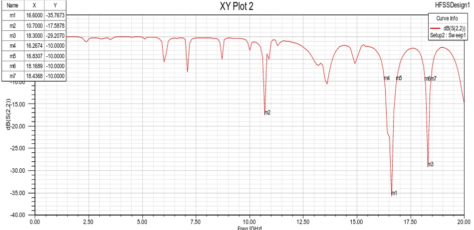
Now a days it is a common practice to evaluate the system performances through computer simulation before the real time implementation. A simulator “Ansoft HFSS” based on finite-element method has been used to calculate return loss, bandwidth, and gains. This simulator also helps to reduce the fabrication cost because only the antenna with the best performance would be fabricated [1]. Figure 2 shows the simulated results of the return loss of the proposed antenna. After Simulation the return loss is obtained -35.7673 dB with gain 5.6925 dB and bandwidth 563 MHz at 16.6 GHz. Frequency Vs Return Loss is shown in fig 2. A negative value for return loss shows that this antenna had not many losses while transmitting the signals. Antenna is another one operated at 18.3 GHz. After simulation return loss is obtained -29.2070 dB with gain 12.44 dB and bandwidth 268 MHz at 18.3 GHz. Frequency Vs Return Loss is shown in fig 2.
Figure 2: Return loss of the Proposed Antenna
0.00 2.50 5.00 7.50 10.00 12.50 15.00 17.50 20.00
Freq [GHz] -40.00
-35.00 -30.00 -25.00 -20.00 -15.00 -10.00 -5.00 0.00 5.00
d
B(S
(2
,2
))
Ansoft LLC
XY Plot 2
HFSSDesign1m1 m2
m3
m4 m5 m6m7
Curve Info dB(S(2,2)) Setup2 : Sw eep1
Name X Y
m1 16.6000 -35.7673
m2 10.7000 -17.5878 m3 18.3000 -29.2070 m4 16.2674 -10.0000 m5 16.8307 -10.0000
363
Gopal
1, ETJ
Volume 3 Issue 01 January 2018
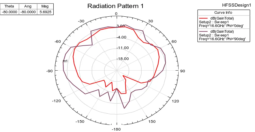
The simulated results for gain that are obtained from the proposed antenna at 16.6 GHz and 18.3 GHz are shown in figure 3 and figure 4 respectively. These figures show
frequency versus gain graph. The gain is given in variation of theta & phi and range of theta and phi is taken from 0 to 90 degree.
Figure 3: Gain of the Proposed Antenna at 16.6 GHz.
Figure 4: Gain of the Proposed Antenna at 18.3 GHz.
Table 1. Comparative analysis of Proposed Antenna & Conventional Antenna
Sr. No. Parameter Base Paper Proposed Antenna
1. Return loss -17.39 db -35.7673 db
2. Gain 5.1 db 12.44 db
3. Bandwidth 40 MHz 563 MHz
4 Resonant frequency 2.4 GHz & 5.5 GHz 16.6 GHz &18.3 GHz
IV.
Conclusion
In this paper, a microstrip patch antenna for various wireless applications has been presented. The microstrip patch antenna mostly used in modern wireless communication. The goal of this paper is to design and simulate microstrip
patch antenna that can operate at 16.6 GHz & 18.3 GHz and study the performance of microstrip antenna briefly. From the simulated results, it is seen that the performance of the proposed antenna is better than the conventional patch antenna. In future, our target is to design another microstrip
-18.00 -11.00 -4.00 3.00
90 60 30
0
-30
-60
-90
-120
-150
-180
150
120
Ansoft LLC Radiation Pattern 1 HFSSDesign1
m1
Curve Inf o
dB(GainTotal) Setup2 : Sw eep1 Freq='16.6GHz' Phi='0deg'
dB(GainTotal) Setup2 : Sw eep1 Freq='16.6GHz' Phi='90deg'
Name Theta Ang Mag
m1 -80.0000 -80.0000 5.6925
-13.00 -6.00 1.00 8.00
90 60 30
0
-30
-60
-90
-120
-150
-180
150
120
Ansoft LLC Radiation Pattern 2 HFSSDesign1
m1
Curve Inf o dB(GainTotal) Setup2 : Sw eep1 Freq='18.3GHz' Phi='0deg'
dB(GainTotal) Setup2 : Sw eep1 Freq='18.3GHz' Phi='90deg'
Name Theta Ang Mag
364
Gopal
1, ETJ
Volume 3 Issue 01 January 2018
patch antenna that can operate at higher frequency. The proposed antenna works at 16.6 GHz and obtained return loss of -35.7673 dB with gain 5.6925 dB and bandwidth 563 MHz. Antenna is also operated at 18.3 GHz and obtained return loss of -29.2070 dB with gain 12.44 db and bandwidth 268 MHz.
References
1. Mst. Nargis Aktar, Muhammad Shahin Uddin, Md. Ruhul Amin and Md. Mortuza Ali (2011), “ Enhanced Gain and Bandwidth of Patch Antenna using EBG Substrates” International Journal of Wireless & Mobile Networks, Volume 3, No. 1, pp 62-69, February 2011.
2. Daihua Wang , Linli Song, Hanchang Zhou and Zhijie Zhang (2012), “A Compact Annular Ring Microstrip Antenna for WSN Applications” Sensors Publication, pp 8663-8674, 2012.
3. S. Azzaz-Rahmani and N. Boukli-Hacene (2012), “Ultra-Wide-Band Microstrip Concentric Annular Ring Antenna for Wireless Communications” International Journal of Computer Science Issues, Volume 9, Issue 1, No 2, pp 132-134, 2012. 4. Shitiz Upreti and Saurabh Katiyar (2012), “Gain
Enhancement of Circular Microstrip Patch Antenna Using Dual-FSS Superstrate Layer for ISM Band” IOSR Journal of Electronics and Communication Engineering, Volume 4, Issue 3, pp 36-40, Nov - Dec. 2012.
5. V. Saidulu, K.Kumara Swamy, K.Srinivasa Rao and P.V.D Somasekhar Rao (2013), “Performance Analysis of Circular Microstrip Patch Antenna With Dielectric Superstrates” IOSR Journal of Engineering, Volume 3, Issue 9, pp 39-51, 2013. 6. Ling Feng Shi and Hong Feng Jiang (2013),
“Vertical Cascaded Planar EBG Structure for SSN Suppression” Progress In Electromagnetics Research, Volume 142, pp 423–435, 2013.
7. Nagendra kushwaha1 and Raj Kumar (2014), “Study of Different Shape Electromagnetic Band Gap (EBG) Structures for Single and Dual band Applications” Journal of Microwaves, Optoelectronics and Electromagnetic Applications, Volume 13, No. 1, pp 16-30, 2014.
8. Vijay Sharma, Krishan Gopal Jangid, D. Bhatnagar, Sanjeev Yadav and M.M. Sharma (2014), “A Compact CPW Fed Modified Circular Patch Antenna with Stub for UWB Applications” International Conference on Signal Propagation and Computer Technology, pp 214-217, IEEE-2014.
9. Jincy Rachel Thomas, Jeena Sara Thomas, T. Mary Neebha and M. Nesasudha (2014), “Design of a Circular Patch Antenna with Admittance Measurement for Wireless Communication”
International Conference on Electronics and Communication System, pp 1-5, IEEE-2014. 10. R. Bargavi, K. Sankar and S. Arivumani Samson
(2014), “Compact Triple band H-Shaped Slotted Circular Patch Antenna” IEEE-International Conference on Communication and Signal Processing, pp 1159-1162, April 3-5,2014.
11. Savita M Shaka, Prashant R.T, Vani R.M and Hunagund P.V (2014), “Study of Microstrip Antenna Using Various Types of EBG Cells” International Journal of Advanced Research in Electrical, Electronics and Instrumentation Engineering, Volume 3, Issue 5, pp 9680-9686, May 2014.
12. Tahsin Ferdous Ara Nayna, A. K. M. Baki and Feroz Ahmed (2014), “Comparative Study of Rectangular and Circular Microstrip Patch Antennas in X Band” International Conference on Electrical Engineering and Information & Communication Technology, pp 1-5, IEEE-2014. 13. Hayat Errifi, Abdennaceur Baghdad, Abdelmajid
Badri and Aicha Sahel (2014), “Improving Microstrip Patch Antenna Directivity using EBG Superstrate” American Journal of Engineering Research, Volume 3, Issue 11, pp 125-130.
14. Nidhi M. Thaker and Vivek Ramamoorthy (2014), “A Review on Circular Microstrip Patch Antenna with Slots for C Band Applications” International Journal of Scientific & Engineering Research, Volume 5, Issue 12, pp 1039-1043, December 2014.
15. Navneet Saroha and Manjeet Goyat (2015), “Design & Simulation of Rectangular & Circular Patch Antenna with EBG Substrates” International Journal of scientific research and management, Volume 3, Issue 7, pp 3407-3410, 2015.
16. Ayyappan M, Manoj B, Dr. Stephen Rodrigues (2016), “Low Return Loss Circular Microstrip Patch Antenna at 5.8GHz for Wide-band Applications” International Conference on Electrical, Electronics, and Optimization Techniques, pp 3023-3026, IEEE-2016.
17. Xiyao Liu, Yuanxin Li, Zhixi Liang, Shaoyong Zheng, Juhua Liu and Yunliang Long (2016), “A Method of Designing a Dual-Band Sector Ring Microstrip antenna and its Application” IEEE Transactions on Antennas and Propagation, pp 1-6, IEEE-2016.
18. Sibi Chakravarthy S, Sarveshwaran N, Sriharini S and Shanmugapriya M (2016), “Comparative Study on Different Feeding Techniques of Rectangular Patch Antenna” pp 1-6, IEEE-2016.
365
Gopal
1, ETJ
Volume 3 Issue 01 January 2018
antenna using E Shaped slot technique for 5.75 GHz ISM Band Applications” 5th International Conference on Informatics, Electronics and Vision, pp 449-453, IEEE-2016.
20. Komal V. Tumsare and Dr. P. L. Zade (2016), “Microstrip Antenna using EBG Substrate” International Journal on Recent and Innovation Trends in Computing and Communication, Volume 4, Issue 12, pp 73-76, December 2016.