Displacement-Based Seismic Design of Timber Structures
251
0
0
Full text
(2) University of Trento University of Brescia University of Padova University of Trieste University of Udine University IUAV of Venezia. Cristiano Loss (Ph. D. Student). DISPLACEMENT-BASED SEISMIC DESIGN OF TIMBER STRUCTURES. Dr. Daniele Zonta Prof. Maurizio Piazza. March, 2011. All the material in this document is protected by copyright. Any use of the work other than as authorized under copyright law is prohibited..
(3) UNIVERSITY OF TRENTO. Doctoral School in Engineering of Civil and Mechanical Structural Systems Cycle: XXIII. Head of the Doctoral School: Prof. Davide Bigoni. Displacement-Based Seismic Design of Timber Structures. Cristiano Loss Department of Mechanical and Structural Engineering Via Mesiano 77 - 38123 University of Trento - ITALY Phone number: +39 0461 282556 Fax number: +39 0461 882599 E-mail: cristiano.loss@ing.unitn.it. Final Examination 7 April 2011. Board of Examiners Prof. Piazza Maurizio (University of Trento, Italy) Prof. Marotti De Sciarra Francesco (University of Naples “Federico II”, Italy) Prof. Joan Ramon Casas (University of Barcelona “Politecnica de Catalunya”, Spain). (Final Version 7 May 2011).
(4) SUMMARY The research is aimed at developing seismic methods for the design and evaluation of the seismic vulnerability of wooden structures, using a displacement-based approach. After a brief introduction on the seismic behaviour of timber structures, the general Direct Displacement-Based Design (Direct-DBD) procedure and the state-of-the-art are presented, with clear reference to the application of the DirectDBD method to wooden buildings. The strength of the Direct-DBD method is its ability to design structures in a manner consistent with the level of damage expected, by directly relating the response and the expected performance of the structure. The research begins with a description of the procedural aspects of the Direct-DBD method and the parameters required for its application. The research presented focuses on the formulation of a displacement-based seismic design procedure, applicable to one-storey wooden structures made with a portal system. This typology is very common in Europe and particularly in Italy. A series of analytical expressions have been developed to calculate design parameters. The required analytical Direct-DBD parameters are implemented based on the mechanical behaviour of the connections, made with metal dowel-type fasteners. The calibration and subsequent validation of design parameters use a Monte Carlo numerical simulation and outcomes obtained by tests in full-scale. After the description of the Displacement-Based method for one-storey wooden structures, a series of guidelines to extend the Direct-DBD methodology to other types and categories of timber systems are proposed. The thesis presents the case of a multi-storey wood frame construction, which is a simple extension of the glulam portal frame system. Part of this work has been done within the RELUIS Project, (REte dei Laboratori Universitari di Ingegneria Sismica), Research Line IV, which in the years between 2005 and 2008 involved several Italian universities and Italian institutes of research in the development of new seismic design methods. The Project produced the first draft of model code for the seismic design of structures based on displacement (Direct-DBD). This thesis is the background to the section of the model code developed for timber structures..
(5)
(6) SOMMARIO La ricerca è finalizzata allo sviluppo di un approccio agli spostamenti per il progetto e la valutazione della vulnerabilità sismica delle strutture in legno. Dopo una breve introduzione sulle problematiche che caratterizzano il comportamento delle strutture lignee in zona sismica, si presenta la procedura del Direct Displacement-Based Design (Direct-DBD) e il relativo stato dell’arte, con chiaro riferimento alla sua applicazione su edifici in legno. Le potenzialità dell’approccio Direct-DBD si possono ascrivere alla capacità di progettare la struttura in modo coerente con lo stato di danneggiamento previsto. Nella fase iniziale della ricerca sono descritti gli aspetti procedurali e i parametri richiesti per l’applicabilità del metodo Direct-DBD. La parte innovativa del lavoro presentato si incentra sulla formulazione di una procedura basata sul protocollo agli spostamenti applicata alla struttura lignea a portale monopiano. Questa tipologia costruttiva è molto diffusa in Europa e in particolare in Italia. Nel corso del lavoro di ricerca sono state sviluppate relazioni analitiche per il calcolo dei parametri di progetto. La formulazione analitica dei parametri si basa sul modello meccanico implementato per descrivere il comportamento locale delle connessioni che utilizzano connettori a gambo cilindrico. La calibrazione e la successiva validazione dei parametri di progetto si avvale di una simulazione numerica Monte Carlo (MC) e dei risultati ottenuti da prove sperimentali. A valle della formulazione sono proposte linee guida mediante le quali estendere la metodologia proposta ad altre tipologie e categorie di edifici in legno. Per questo, nella tesi, è studiata la tipologia di edificio residenziale multipiano in legno, quale semplice estensione del sistema intelaiato. Il lavoro di studio è stato svolto all’interno della Linea di Ricerca No. 4 del progetto RELUIS (REte dei Laboratori Universitari di Ingegneria Sismica) che nel triennio 2005-2008 ha visto impegnate numerose università ed enti di ricerca italiani nello studio di nuovi approcci alla progettazione sismica. Il progetto si è concluso con la stesura di una prima versione di codice modello per la progettazione di strutture secondo il Direct-DBD, per il quale il lavoro rappresenta il background della parte dedicata alle strutture lignee..
(7)
(8) To my family and my girlfriend.
(9)
(10) ACKNOWLEDGEMENTS La conclusione di questo lavoro segna un passaggio importante della mia vita, un percorso partito molti anni fa in una fredda mattinata di dicembre, dove le alte cime dolomitiche riparano un ambiente semplice e discreto. Da allora ne è passato di tempo e molti sono stati gli ostacoli da superare, le fatiche, ma soprattutto i sacrifici fatti. Molte sono le persone che meritano un “Grazie” e un caloroso abbraccio. È stata anche la loro presenza e i loro consigli che mi hanno permesso di raggiungere questo traguardo. Un doveroso ringraziamento va al Dr. Daniele Zonta per l’incoraggiamento e la fiducia concessami e al Prof. Maurizio Piazza per la sua pazienza e cordialità. Desidero ricordare le persone più care con cui ho dialogato in questi ultimi tre anni. Molto importante è stato l’appoggio e lo stimolo del team di ricerca che si occupa delle strutture lignee, coordinato dal Prof. M. Piazza e composto in ordine da Acler Ermanno, Andreolli Mauro, Polastri Andrea, Sartori Tiziano e Tomasi Roberto. Sono grato a tutte le persone che lavorano presso il Dipartimento di Ingegneria Meccanica e Strutturale dell’Università di Trento (DIMS), in particolare Rosanna Verones, Cesarina Zeni, Elena Staltari e Michela Litterini, che mi hanno seguito nel lungo percorso amministrativo della scuola di dottorato. Una dedica particolare spetta ai miei genitori, ai miei nipotini e ai miei fratelli per tutto il loro affetto e alla mia ragazza Ilaria, che mi ha irraggiato di gioia e amore in questi ultimi tre anni. Molte altre persone inconsapevolmente mi hanno aiutato e accompagnato in questo percorso tortuoso e lungo – a tutti voi un sentito grazie di cuore! –. Imér, Marzo 2011 Cristiano Loss.
(11)
(12) CONTENTS. ACKNOWLEDGEMENTS CONTENTS. I. LIST OF FIGURES. V. LIST OF TABLES. XII. NOMENCLATURE. XV. 1. 2. INTRODUCTION. 1. 1.1. General. 1. 1.2. Objectives and scope. 4. 1.3. Dissertation overview. 5. EARTHQUAKES AND WOOD STRUCTURES. 7. 2.1. Performance of wood in earthquake conditions. 7. 2.2. Suitable wood construction systems in seismic zones. 8. 2.3. Timber frame systems with moment-resisting connections. 16. 2.4. Timber frame panel systems. 19. 2.5. Massive wood panel system. 24. 2.6. Conclusions. 28 -I-.
(13) 3. DIRECT DISPLACEMENT-BASED DESIGN METHODOLOGY. 29. 3.1. Introduction. 29. 3.2. Overview of the Direct-DBD procedure for MDOF System. 30. 3.3. State of development in timber systems. 33. 3.4. Conclusions. 40. 4. PROPOSED DIRECT-DBD METHOD FOR TIMBER SYSTEMS. 41. 4.1. General. 41. 4.2. Structure description. 41. 4.3. Load-slip monotonic curve for fasteners. 45. 4.4. Design displacement formulation. 57. 4.5. Ductility. 66. 4.6. Equivalent viscous damping. 67. 4.6.1. Cyclic behaviour of dowel type fastener connections. 4.6.2. Formulation of the equivalent viscous damping analytical. model. 79. 4.7 5. 68. Conclusions. 88. VALIDATION OF THE PROPOSED DIRECT-DBD METHOD. 89. 5.1. Dynamic behaviour of timber structures. 89. 5.2. Numerical model for non-linear static analysis. 91. 5.2.1. General aspects. 91. 5.2.2. Pushover analysis and results. 93. 5.3. Numerical model for non-linear dynamic analysis. 95. 5.3.1. General. 5.3.2. Analytical evaluation of the moment-rotation curve for joint. connections 5.3.3. Time-history analysis. 95 96 104. 5.4. EXPERIMENTAL RESULTS. 104. 5.5. VALIDATION OF DESIGN DISPLACEMENT. 119. 5.5.1. - II -. Analysis results. 123.
(14) 5.5.2. 6. Numerical calibration of design displacement. 127. 5.6. Validation of Equivalent Viscous Damping. 129. 5.7. Conclusions. 142. EXTENSION. OF. DIRECT-DBD. METHOD. TO OTHER. TIMBER. BUILDINGS. 7. 143. 6.1. General. 143. 6.2. Moment-resisting joint for general dowel configuration. 143. 6.3. Wood light-frame system. 148. 6.3.1. General. 148. 6.3.2. Direct-DBD: formulation of design displacement. 150. 6.3.3. Direct-DBD: formulation of the equivalent viscous damping. 158. 6.3.4. Non-linear model for wood shear walls buildings. 162. 6.4. Comparison of results for the proposed analytical model. 168. 6.5. Conclusions. 175. SUMMARY, CONCLUSIONS AND RECOMMENDATIONS. 177. 7.1. Summary and conclusions. 177. 7.2. Future work. 179. BIBLIOGRAPHY. 181. APPENDIX A. 193. 7.3. Pre-processing. 195. 7.4. Solving. 197. 7.5. Post-processing. 198. APPENDIX B GLULAM PORTAL FRAME SYSTEM APPENDIX C. 199 200 213. - III -.
(15) APPENDIX D. - IV -. 217.
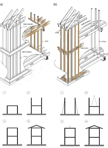
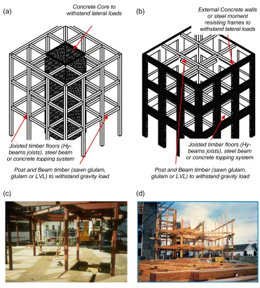
(16) LIST OF FIGURES. Figure 1.1. Overview of building damage after recent two earthquakes: Northridge 1994 with Magnitude of 6.7 and Kobe (Hanshin-Awaji) 1995 with Magnitude of 7.2 (Richter scale). 2. Figure 1.2 Typical performance curve for a structure with relation between displacement/force and damage (modified from Calvi 2003). 3. Figure 2.1 (A) Typical stress-strain curves for clear coniferous wood (Piazza et al. 2005); (B) Experimental load-slip curves for joints in tension parallel to the grain (Racher 1995a). 9. Figure 2.2 Selection of ductile timber structures; (a) Moment-resisting (MR) timber frame system; (b) Timber shear panel system; (c) Cross-laminated timber panel system; (modified from Priestley et al. 2007). 10. Figure 2.3 Post-tensioned timber frame system (modified from Priestley et al. 2007) 10 Figure 2.4 (a) MR joint built with flanged elements (from Piazza et al. 2005); (b) MR joint built with glued elements (from Racher 1995c); (c) MR joint built with epoxy steel rods (from Piazza et al. 2005). 11. Figure 2.5 (a) Platform frame system (Common in 1940s in the USA): details of structure and construction sequence, from 1 to 4; (b) Balloon frame system: details of structure and construction sequence from 1 to 4 (modified from American Forest and Paper Association 2001). 13. Figure 2.6 Prestressed System; (a) North-east perspective view of the University of Canterbury Biological Science building (modified from Fernandez 2008); (b) South-west perspective view of the University of Canterbury building (modified from Fernandez 2008). 14. Figure 2.7 Hybrid systems, suitable for tall timber buildings up to 25 storeys; (a) Three-dimensional view of the whole resisting system in configuration No 1 (modified from Sakamoto et al. 2004); (b) Three-dimensional view of -V-.
(17) the whole resisting system in configuration No 2 (modified from Sakamoto et al. 2004); (c) Phase of realization of the flooring (from Fragiacomo 2009); (d) Phase of erection of post and beam gravity load resisting element (from Fragiacomo 2009). 15. Figure 2.8 3D View (I) and exploded view of the scheme of assembly (II); (a) Dowelled cross-lapped joint; (b) Internal metal plates connected with fasteners; (c) Nailed plywood gussets or metal plate with fasteners Figure 2.9. (Gojkovic and Stojic 1996) Figure 2.10. 17. Drawing of the common bracing systems between timber frames 18. Commercial “Kerto” portal frame solution for light industrial,. warehouse, agricultural or equestrian buildings; Three dimensional view of prefabricated elements (modified from Finnforest 2009). 19. Figure 2.11 (a) Three-dimensional view of the Timber Portal frame system with dowelled cross-lapped joints (so-called “heavy timber structure”); (b) Details of an industrial warehouse built in Trentino (Italy). 20. Figure 2.12 Details of wall-to-floor joints of platform frame system construction (courtesy of Professor Ian Smith) Figure 2.13. 21. Schematic presentation of the timber frame panel construction. following the platform frame technique; (a) exploded view of wood frame building; (b) shear wall layers; (c) shear wall panel module; (d) sections of shear wall panel module and mechanical fasteners of wood-based sheathing panels; (Pictures Modified from Premrov 2008). 22. Figure 2.14 wood frame resistance system: mechanism of lateral resisting system (modified from Ceccotti and Touliatos 1995) Figure 2.15. 23. Schematic presentation of the massive wood panel construction. (XLAM system); (a) exploded view of massive wood panel system; (b) shear wall layers of cross-laminated solid wood panels. 25. Figure 2.16 Illustration of XLAM lateral resisting system; Details of connections between the elements (modified from Binderholz 2010). 27. Figure 3.1 Fundamentals of Direct Displacement-Based Design (based on Priestley et al. 2007). 31. Figure 3.2 (a) Wayne Stewart degrading hysteresis rule described by Filiatrault et al. (2003); (b) The nine independent physical parameters of Wayne Stewart degrading hysteretic model Figure 3.3. 34. Single family house with two storeys, as in a modern residential construction in California (Curee 2008); (a) Structure finished before the test; (b) Lateral view after the test; (c) 3D view after the test. - VI -. 35.
(18) Figure 3.4. Global view of the four index buildings investigated (modified from Filiatrault et al. 2004). 36. Figure 3.5 Flowchart of Direct-DBD procedures developed for mid-rise wood frame buildings (modified from Pang and Rosowsky 2007). 38. Figure 3.6 (a) Elevation views of a three-storey wood frame structure, typical in America; (b) Three-dimensional nonlinear model for a three-story wood frame structure (modified from Pang and Rosowsky 2007). 39. Figure 4.1 Description of the case study; (a) 3D isometric view of the main resistant structure; (b) Geometrical description of the beam-to-column joint Figure 4.2 Geometric features of the prototype portal. 42 43. Figure 4.3 Design Force acting on a single dowel for knee joints made with two crowns of dowels; (a) Beam-to-column connection with no parallel elements and geometrical configuration; (b) Forces acting on dowels due to rigid body rotation (modified from Racher 1995b). 45. Figure 4.4 Failure modes provided by the European Yield Model for fasteners in double timber-to-timber shear planes (modified from Leijten 2008) Figure 4.5. 47. (a) Typical monotonic load-slip curves for a dowel-type timber. connection; (b) Analytical models for the connections with main parameters. 48. Figure 4.6 Definition of yielding parameters for a monotonic load-slip curve in two typical situations; (a) Load-slip curve with two well-defined linear parts; (b) Load-slip curve without two well-defined linear parts; (modified from CEN 2001). 49. Figure 4.7 Flow-of-forces in dowel-type fastener connections, embedment strength in timber elements and model of embedment strength (modified from Leijten 2008). 51. Figure 4.8 Embedment strength of a dowel-type fastener connection in parallel and perpendicular directions; (a) Test parallel to grain direction; (b) Test perpedicular to grain direction (modified from Sawata and Yasumura 2002) Figure 4.9. 52. (a) Test failure mode after reaching maximun load; (b) Normalized moment-angle diagram of a dowel-type fastener for different dowel diameters, d (modified from Blass et al. 2000). 53. Figure 4.10 (a) Analytical Load-Slip curve formulated; (b) Experimental Load-Slip curve after monotonic test (push out test of two-dowel-type connections of 12 mm; Piazza et al. 2009) Figure 4.11. 54. Möller’s chart of dowel-type mechanical fasteners for different. geometries and mechanical configurations. 56. - VII -.
(19) Figure 4.12 Conceptual model for estimating the design displacement d. 58. Figure 4.13 Moment and shear stresses on dowels arranged in two concentric crowns. 61. Figure 4.14 Spacings, edge distances and end distances for dowels on a knee joint made with two crowns of dowels Figure 4.15. 62. (a) Test on specimen with 12 dowels of 16 mm in diameter; (b). Connection failure mode after test (ultimate state for joint); (c) Dowel deformation after test (modified from Polastri et al. 2008). 63. Figure 4.16 Typical force-deformation loops for different load levels of dowelled joints under cyclic loading (modified from Ceccotti 1995). 69. Figure 4.17 Typical cyclical behaviour of a nailed connection with nail slenderness of 8.5; The red line shows the Envelope curve (Ceccotti 1995). 71. Figure 4.18 Failure of connections with metal dowel-type fasteners in double-shear; (a) Mode II in accordance with the EYM (CEN 2004a); (b) Mode III in accordance with the EYM (Courtesy of Professor Maurizio Piazza). 72. Figure 4.19 Qualitative trend of the cyclic response of a connection with dowel-type fasteners in double shear for failure mode III (European Yield Model; CEN 2004a). 73. Figure 4.20 Expected hysteretic loops of a connection with dowel-type fasteners in double shear subjected to cyclic loading (failure mode III in accordance of European Yield Model). 74. Figure 4.21 Analytical load-slip curve of a dowel-type fastener connection (black line); Expected load-slip curve of a dowel-type fastener connection (red line) Figure 4.22. 75. Failure Mode III dowel-type fastener connections in double shear;. Johansen’s model. 76. Figure 4.23 Configuration of equilibrium (hypothetical) after the reaching of Failure Mode III, for a dowel-type fastener connection in double shear, on return to the undeformed situation. 77. Figure 4.24 Idealization of the hysteretic loop for a dowel-type fastener connection based on three different loading histories; (a) Protocol I; (b) Protocol II; (c) Protocol III. 81. Figure 4.25 Procedure for cyclic testing following EN 12512 (CEN 2001); Ratio between series of cycles Figure 4.26. 84. (a) Ultimate configuration of joint: slip of dowels due to inelastic. deformation; (b) Dowelled cross-lapped joint; (c) Load-slip envelope curve of dowels. - VIII -. 85.
(20) Figure 5.1 Hysteresis models developed for timber structures (modified from Dolan 1994); (a) Kivell et al. (1981) hysteresis model; (b) Dolan (1989) hysteresis model; (c) Stewart (1987) hysteresis model (d) Ceccotti and Vignoli (1990) hysteresis model. 90. Figure 5.2 (a) Moment-rotation “Florence” model (Ceccotti and Vignoli 1989) of a semi-rigid joint with typical loop shape in cyclic response; (b) Parameters required by the proposed constitutive relation (modified from Dolan 1994). 91. Figure 5.3 (a) Finite element model implementation for structural model; (b) beamto-column joints with an elastic-perfectly-plastic load-slip relationship of the dowels Figure 5.4 (a) Ductile collapse mode; (b) brittle collapse mode. 92 94. Figure 5.5 FEM II numerical model and joint definition for non-linear time-history analyses. 95. Figure 5.6 Scheme of joints for the Moment-Rotation curve evaluation; (a) Yield of joints; (b) Ultimate state of joints. 97. Figure 5.7 (a) Moment-Rotation law for dowelled cross-lapped joint with two crowns of dowels; (b) Yield moment formula; (c) Ultimate moment formula; (d) Yield rotation formula; (e) Ultimate rotation formula; (f) definition of rotational ductility. 103. Figure 5.8 (a) Geometrical dimensions of the specimen tested by Polastri et al. (2008); (b) Static design of specimen. 105. Figure 5.9 (a) Test arrangement; (b) Cyclic displacement sequence; (c) Moment versus rotation responses for cyclic loading. 106. Figure 5.10 Inelastic displacement response curve for test based on the EN 12512 (CEN 2001) loading protocol. 107. Figure 5.11 (a) Loading protocol in cyclic tests in accordance with the complete procedure of EN 12512; (b) Definition of equivalent viscous damping ratio in a cycle (modified from EN 12512; CEN 2001) Figure 5.12. 108. Fitting curves of equivalent viscous damping versus displacement. ductility. 110. Figure 5.13 Superposition of the the envelope Moment-rotation curves, theoretical and experimental, on the full cyclical response of the MR joint. 111. Figure 5.14 Comparison of displacement between the pushover curve provided by the FEM I Model and the experimental curve. 112. Figure 5.15 (a) Finite element model for non-linear time history analysis (FEM II); (b) moment-rotation Pivot hysteretic model with measured experimental values. 113. - IX -.
(21) Figure 5.16. Comparison of moment-rotation relationship, with the experimental. dataset for two levels of displacement and three cyclic loading sequences. 114. Figure 5.17 (a) Chart of stress-strain curve after tensile test of steel wire of dowels; (b) Mechanical properties of dowel measured (modified from Polastri et al. 2008). 118. Figure 5.18 Trends of input variables selected in the MC Simulation; Probability distribution f(x) for the function x; Probabilistic models for properties for glued laminated timber in accordance with JCSS (2007). 122. Figure 5.19 (a) Histogram of displacement error E%(d)(%) (, average value; , standard deviation). 123. Figure 5.20 (a) Displacement error chart in function of the displacement ratio j (joint displacement) to d (total deformation) and histogram without gravity coefficient cG; (b) Displacement error chart in function of the displacement ratio j (joint displacement) to d (total deformation) and histogram with gravity coefficient cG (, average value; , standard 2. deviation, R , coefficient of determination). 125. Figure 5.21 Displacement error E%(d) for the calibrated formula to estimate design displacement d. 128. Figure 5.22 Geometrical dimensions of the three case studies investigated. 131. Figure 5.23 (a) Selection of the accelerograms; (b) Elastic displacement response spectra. 135. Figure 5.24 Pushover curve for the three case studies analyzed. 136. Figure 6.1 (a) Load distribution for a group of dowels in a rhombic pattern due to bending (M) and shear (V); (b) Design scheme dowel-type MR joint 144 Figure 6.2 Load distribution for a group of dowels in a generic pattern due to bending (M) and shear (V). 148. Figure 6.3 (a) Failure mode of nails under cyclic actions: nails crush wood fibres and cavity is formed at the edges of joined material; (b) Impartment of the strength F between the first and the third load cycles with the same deformation; (c) Energy dissipated during a cycle: due to embedment of wood and plasticity of the connections; (d) Global seismic response of a full-scale residential building (pictures modified from Ceccotti 1995) 149 Figure 6.4 Modified Möller’s diagram for nails with diameter ranging from 2 mm to th. 3.1 mm and steel strength ranging from 5 to 95 Figure 6.5 Displacement decomposition of shear walls. th. 152 153. Figure 6.6 Displacement decomposition of shear walls, with the contribution of each component. -X-. 154.
(22) Figure 6.7 Analytic model to evaluate bending displacement (b). 154. Figure 6.8 Analytic model to evaluate shear displacement (v). 155. Figure 6.9 Analytic model to evaluate displacement due to slip of nails (n). 156. Figure 6.10 Failure mode II of fasteners in single shear panel-to-timber connections 159 Figure 6.11. Restoring situation of fastener in single shear panel-to-timber. connection. 160. Figure 6.12 Description of the CASHEW model (modified from Filiatrault and Folz 2002). 164. Figure 6.13 Evolutionary Hysteretic Parameter Model (EPHM) developed during the NEESWood project (modified from Pei and van de Lindt 2007) Figure 6.14. 167. (a)Shear wall structure; (b) Mechanical parameters with defined. probability density functions. 168. Figure 6.15 (a) Shearwall backbone curve parameters; (b) Equivalent linearization of non-linear backbone curve (modified from Pang and Rosowsky 2007) 169 Figure 6.16 Backbone curve for a set of shear walls and in dots the corresponding design force/displacement analytical evaluation (adopted Judd & Fonseca modified model). 172. - XI -.
(23) LIST OF TABLES. Table 4.1 Geometrical limits of the portals commonly adopted in Europe. 43. Table 5.1 Experimental measured parameters and estimated equivalent viscous damping value Table 5.2 Proposed equivalent viscous damping value for the test specimen Table 5.3. 109 110. Parameters of Priestley’s viscous analytical model, calibrated using outcomes of test. 110. Table 5.4 Error in the equivalent viscous damping in cycle 5 and cycle 6 of test. Experimental versus numerical data using FEM II Model Table 5.5. 115. Error in the equivalent viscous damping evaluated for the design displacement d; Experimental versus analytical values with elasticperfectly plastic curve of connectors. Table 5.6. 117. Error in the equivalent viscous damping evaluated for the design displacement d; Experimental versus analytical values with elastoplastic hardening curve of connectors. 118. Table 5.7 Summary of main statistical quantities for displacement error E%(d) 128 Table 5.8 Geometrical and mechanical parameters of the three cases investigated 132 Table 5.9. Moment-rotation Pivot hysteretic curve parameters of the beam-tocolumn joint for the three cases. 133. Table 5.10 Results of Non-Linear Time History Analyses (NLTHA). 137. Table 5.11 Pushover results of the three case studies (CASE A, B and C). 138. Table 5.12 Analytical EVD versus average value of EVD evaluated via non-linear time-history analyses (NLTHA). 138. Table 5.13 Numerical mean value of EVD versus analytical prediction of EVD for the three cases studied Table 5.14 Final values of EVD for the three cases examined. - XII -. 139 141.
(24) Table 6.1. Backbone numerical parameters for shear walls built with different configurations of connectors (selection from Pang and Rosowsky 2007) 170. Table 6.2 Comparison between backbone parameters and estimated parameters for the selected shear walls Table 6.3 Error in evaluation of shear wall design parameters. 171 172. Table 6.4 Equivalent stiffness, keq (kN/mm) at target drift (% of wall height) for shear walls built with different configurations of connectors (selection from Pang and Rosowsky 2007). 173. - XIII -.
(25)
(26) NOMENCLATURE The nomenclature used within this text is in agreement with the Safety Structural Code developed by the European Committee for Standardization, known as EUROCODE. The following nomenclature is used throughout this thesis: A. Area. a. half the length of the rhombic area in the horizontal direction. aeq. Parameter to define pitch between two connectors. ag. Ground acceleration. As. Cross-section area of studs. aw. Aspect ratio of each sheathing panel. b. half the length of the rhombic area in vertical direction. bb. Thickness of section of the beam. bc. Thickness of section of the column. bw. Wall panel width. C. Constant defined based on hysteretic model. c2. Semi-empirical numerical parameter to define edge distances for dowels on a knee joint. cEVD. Calibration coefficient for Equivalent Viscous damping model (EVD). cG. Coefficient to reduce inelastic displacement. CJ. Dimensionless configuration parameter of the beam-to-column joint. cp,1. First calibration parameter. cp,2. Second calibration parameter. crwall. Reduction factor. cscal. Scaling factor of PGA. cw. Number of sheathing panels along the length of edge of the frame. d. Diameter of connector. E. Timber elastic modulus. E%(d). Error in displacement (percentage value). - XV -.
(27) Edis,dowel,ext. Dissipated energy by internal connectors. Edis,dowel,int. Dissipated energy by external connectors. Edis,J. Dissipated energy by the beam-to-column joint. Ediss. Energy dissipated per half cycle. Ee Ef. Energy dissipated between the instant in which the fastener regains stiffness from contact with the wooden surface and the instant when the previous displacement is reached Energy dissipated by the effects of friction and plastic deformation of the connector in the recovery phase of the initial configuration. Ehyst,joint. Hysteretic energy dissipated by the beam-to-column Joint. Ehysteretic. Hysteretic dissipated energy by the structure. en. Slip of the nailed connection at a corner of the sheathing panel. Ep. Energy dissipated by plastic deformation of connector during the loading phase. Epot. Available potential energy per half cycle. Estorage. Potential energy; Available potential energy. Eeq,JOINT. Error in equivalent viscous damping of the beam-to-column Joint. F. Force; Load. F0,FBM. First parameter of Foschi and Bonac model. Ff. Restoring Force. fh. Embedment strength. fh,0,k. Characteristic embedment strength along the grain. fh,1,k. Characteristic embedment strength of external timber member. fh,2,k. Characteristic embedment strength of central timber member. fh,f,k. Characteristic embedment at an angle f to the grain. fm. Bending strength. FM. Component stress due to bending moment of the most critical dowels; Forces on the connectors due to bending moment. FM,e. Forces on the connectors in external crown due to bending moment. FM,i. Component stress due to bending moment of the ith dowel. fm,k. Characteristic bending strength. Fn. Yield Force. FN,i. Component stress due to axial force of the ith dowel. Fu. Ultimate Force. fu. Ultimate strength of steel. fu,exp. Experimental value of the ultimate strength of the connector. fu,k. Characteristic tensile strength of connectors. FV. Component stress due to shear of the most critical dowels; Forces on the connectors due to shear force. FV,d,i. Total force acting on the i dowel. FV,i. Component stress due to shear of the ith dowel. FV,w. Shear resisting force of the shear wall, Load-carrying capacity of the shear wall. - XVI -. th.
(28) Fw. Force at the top of shear wall. Fy. Bearing capacity; Load-carrying capacity of connector; Shear capacity. Fy,exp. Experimental value of the yield strength of the connector. fy,exp. Experimental value of the yield strength of the connector. g. Acceleration of gravity. Gp. Shear modulus for the sheathing panels. h. Depth of section of the elements in beam-to-column Joint. hb. Depth of section of the beam. hc. Depth of section of the column. Hc. Column height. He. Effective height of building. Hi. Height of the i-mass locations of the structure. hw. Wall panel height. i. Space between portals (pitch). Jb. Moments of inertia of the beam. Jc. Moments of inertia of the column. k0, FBM. Third parameter of Foschi and Bonac model. k1, FBM. Second parameter of Foschi and Bonac model. kd,i. Stiffness of the ith dowel (slip direction). ke. Effective stiffness. keq. Equivalent stiffness. ki. Initial stiffness of building; Initial stiffness. krc. Stiffness in recharge phase of loading. ks. Secant stiffness. kSER. Slip modulus. kULS. Ultimate slip modulus. k. Rotational stiffness. ku. Ultimate rotational stiffness. ky. Elastic rotational stiffness. L. Length. LL. length in the longitudinal direction of warehouse. lw. Diagonal length of the sheathing panel. m. Number of portals. M. Bending moment. me. Equivalent mass. mi. Mass of the i-mass locations of the structure. MJ. Bending moment acting on the beam-to-column Joint. MR,b. Yield moment of the beam; Resisting moment of the beam. - XVII -.
(29) MR,J. Bending capacity of the beam-to-column Joint. Ms. Moment of equilibrium in the return of the configuration to its undeformed state. ms. Number of nail spacing along the length of the sheathing panel. Mu. Ultimate bending moment of the beam-to-column joint. My. Yield moment. My,Rk. Characteristic fastener yield moment. n. Number of modes. n1. Number of connectors in the first crown. n2. Number of connectors in the second crown. ncrowns. number of crowns in the moment-resisting connections. neq,el. Equivalent number of dowels for the elastic range. neq,pl. Equivalent number of dowels for the plastic range. next. Number of connectors in external crown. nint. Number of connectors in internal crown. NJ. Axial Force acting on the beam-to-column Joint. nj. Number of dowels in the jth crown of the beam-to-column Joint. Nnails. Number of “resisting” connections. ns. Number of nail spacing along the height of the sheathing panel. ntot. Total number of connectors. P. Force; Base shear. PGA. Peak ground acceleration. q. Load acting on a structure in a quasi-permanent combination. qlim. Vertical load leading to structure collapse due only to gravity load (ultimate static condition). R. Internal beam radius. r. Radius of the crown. r1. Radius of the first crown. r2. Radius of the second crown. rext. External radius. ri. Radius of the ith dowel. rint. Internal radius. rj. Radius of the jth crown of the moment-resisting connections. Rk. Characteristic load-carrying capacity. rki. Post yield stiffness. rmax. Maximum distance between the rotation centre C and the most critical dowel. SA(T). Period-dependent response acceleration coefficient from response spectrum. snails. Spacing of nails. t. Time. T. Period. - XVIII -.
(30) t1. External member thickness. t2. Central member thickness. TC. Upper limit of the period of the constant spectral acceleration branch. TD. Value defining the beginning of the constant displacement response range of the spectrum. Te. Effective period. tp. Effective thickness of the sheathing panels. Ts. Fundamental period of structure. u. Slip. v. Displacement of the connections. VB. Base shear; Design base shear. VJ. Shear stress acting on the beam-to-column Joint. vy. Displacement at yield of the connections. W. Seismic weight. θ. inter-storey drift. . Displacement. b. Elastic bending displacement of members. d. Design displacement. d,experimental. Design displacement estimated via data tests. d,NLTHA. Maximum (design value) displacement evaluated via Non-Linear Time-History Analyses. d,numerical. Design displacement estimated via numerical analyses. d,PUSH. Displacement extracted by the non-linear static analyses (pushover). i. Design displacement of the ith mass locations of the structure. j. Inelastic displacement. n. Non-linear displacement induced by the panel-to-frame connections. p. Plastic displacement; Inelastic displacement. s. Elastic displacement. t. Target displacement. t,max. Maximum value of the target displacement. u. Ultimate displacement. v. Shear displacement of the panel. y. Yield displacement. . Increase of slip compared to the past. . Rotation. u. Ultimate rotation. y. Yield rotation. . Angle. d. Over-strength design factor. f. Angle between a force and the direction of grain. - XIX -.
(31) HHT. Third coefficient of the Hilber Hughers-Taylor (HHT) method for numerical integration. n. n-eigenvalue. Pivot. First coefficient of Pivot model. r. Roof slope. R. Overstrength factor. sh. Hardening coefficient. sh,measured. Hardening of steel on the connector. . Ratio between the embedment strength of the members. HHT. Second coefficient of the Hilber Hughers-Taylor (HHT) method for numerical integration. k. Ratio between the initial stiffness and the stiffness in recharge phase. Pivot. Second coefficient of Pivot model. t. Ratio between the depth of timber section and radius of the moment-resisting connection. t,II. Geometrical dimensionless parameters. . Slip. i. Tangential slip. u. Ultimate slip. y. Yield slip. . Strain. y. Yield strain of timber. HHT. First coefficient of the Hilber Hughers-Taylor (HHT) method for numerical integration. jn. The n-participation factor of the jth level of the building. t. Ratio of timber portal length to section depth. Pivot. Third coefficient of Pivot model. . Ductility of the structure; Displacement ductility; Static ductility. . Rotational ductility. . Static slip ductility. t. Aspect ratio of portal frame. exp. Experimental value of the wood density. k. Characteristic density of wood. m. Mean density of glulam. . Stress. F. Ratio between the restoring force and the bearing capacity. f=b/a. Ratio between the half of sides of the perimeter that encloses the MR connection. . Damping ratio. d. Design damping; Design value of Equivalent Viscous Damping(EVD). eq. Equivalent viscous damping (EVD). eq,dowel. Equivalent viscous damping of connectors. - XX -.
(32) eq,i,dowel. Equivalent viscous damping of the ith connector. eq,JOINT. Equivalent viscous damping of the joint. eq,NLTHA. Equivalent viscous damping evaluated via Non-Linear Time-History Analyses. hyst. Hysteretic viscous damping. . Constant viscous component. - XXI -.
(33)
(34) 1 1.1. INTRODUCTION. General. The performance of wooden buildings under very severe seismic forces was verified following the Northridge (1994) earthquake in the United States, and the earthquake in Kobe (1995), which affected a wide area of Japan in 1995. The former, in particular, highlighted the inadequacies of some wooden structures in regard to post-earthquake usability, as a result of significant structural and nonstructural damage, expecially when buildings were not appropriately designed (See Karacabeyli and Popovski 2003). Some images of earthquake consequences highlight structural problems and damage found to the buildings (Figure 1.1). Many of the structures that were seriously compromised by the earthquakes in Kobe and Northridge were later demolished in the phase of post-seismic operations. It is clear that the cost of repair or reconstruction of buildings after an earthquake can be very high. For some classes of buildings, we need to ensure full or partial use after the earthquake, so that essential services can be maintained. Moreover, today’s demand for more sustainable technologies has led to the rediscovery of building techniques and materials that better satisfy this condition. Wood is one of these materials and it is no coincidence that in North America two research projects have been financed, both aiming to mitigate the effect of earthquakes on wooden residential buildings (NEESWood Project; Seesl 2006 and CUREE-Caltech Woodframe Project; Curee 2008). So the new challenge in seismic design is to build structures in which the acceptable level of damage caused by the earthquake is predetermined. This means implementing a reliable design code that relates the building performance, damage and the intensity of ground motion as much as possible (Karacabeyli and Popovski 2003).. -1-.
(35) CHAPTER 1. (a) and (b): damage to. wooden buildings after the Northridge California,. Earthquake; 1994. (FEMA. 2010). (a). (b) (c). (c) and (d): damage and collapse. of. wooden. buildings after the Kobe Earthquake; (Kitagawa. and. Hiraishi. 2004). (d). Figure 1.1. Overview of building damage after recent two earthquakes: Northridge 1994 with Magnitude of 6.7 and Kobe (Hanshin-Awaji) 1995 with Magnitude of 7.2 (Richter scale). -2-.
(36) INTRODUCTION. Laboratory work has helped to clarify the relation between damage to structural elements and the displacement/strain level. To identify the displacement as a criterion for design is, therefore, to control the damage mechanism and to predict the expected economic losses due to an earthquake (Calvi 2003). In the seismic structure design, using displacement-based methods, design criteria are provided in terms of displacement. In displacement-based methods the problem is reduced to the evaluation of displacement available and displacement required for earthquake resistance (Calvi 2003). The safety of the structure is thus evaluated by the comparison of displacements. Figure 1.2 shows the typical ForceDisplacement (F-) capacity curve of a structure in the post-elastic state of deformation. In the inelastic field, the displacement, increases without significant changes in the force, F, measured on the F- curve. The trend of the convex curve F- is very common in ductile structures, regardless of the material and the construction typology.. F Base Shear F. . Roof Displacement. Figure 1.2 Typical performance curve for a structure displacement/force and damage (modified from Calvi 2003). with. relation. between. The red lines of Figure 1.2 show the efficiency of displacement in assessing structure performance in the inelastic range. It is otherwise very difficult to control the performance, based only on force.. -3-.
(37) CHAPTER 1. Displacement-based design methods, as a class, are characterised by groups of algorithms which can differ significantly in their application. Currently, there is no agreement on which method is better in terms of reliability. A comprehensive review of the literature on the subject is reported in Fib Bulletin 25 (Calvi 2003). The same author shows that it is difficult to evaluate the applicability of each procedure based on the state-of-the-art. The following work is aimed at developing a seismic design procedure, applicable to wooden structures. The proposed procedure, for the design and evaluation of seismic vulnerability of timber buildings, is in the class of displacement-based methods and is known as Direct Displacement-Based Design (Direct-DBD) method. The Direct-DBD is a procedure in which the input design parameter is the displacement value and in which no iterative procedures are required in the computational phase. Priestley formulated the Direct-DBD procedure in 1993 and then codified it in 2003, for concrete structures (1993, 2003). Recently Priestley et al. (2007) have published a book on the Direct-DBD approach, describing the state of development for different materials and construction typologies and presenting a first draft model code.. 1.2. Objectives and scope. This work aims to allow the application of Direct-DBD to wooden structures. The analytical method developed focuses on buildings used in the European construction market. The specific objectives are to:. I.. develop analytical expressions for the estimation of design parameters required by Direct Displacement-Based Design (Direct-DBD),. II.. validate the analytical model to predict with qualitative confidence the real values of design parameters,. III.. define guidelines to apply the Direct -DBD method to a generic structure in wood,. -4-.
(38) INTRODUCTION. IV.. draft a model code, a commentary and some design examples on new built structures.. Although the analysis has been developed with reference to wooden structures identified as system with single degree of freedom (SDOF), the design model can be easily extended to structural systems with more degrees of freedom (MDOF). In this thesis the model has been extended to MDOF systems used in residential wooden construction. The use of a Direct-DBD procedure implies some inherent difficulties in the design process, since assessing the safety is expressed in terms of displacement. This design philosophy is very different from the static design method, in which the safety verification utilizes the force or stress level reached in each structural element. Displacement is a parameter related to the damage to the structural and nonstructural elements. The use of displacement in the design process in the DirectDBD method allows a prediction of the damage following an earthquake and, thus enables planning for the depreciation cost of buildings, repair costs, or demolition work, in the post-seismic conditions.. 1.3. Dissertation overview. In Chapter 2 various aspects of the seismic response of timber constructions are described. The description of construction typologies, accompanied by the assembly design rules, highlights the role of connections in the global behaviour of a structure. Chapter 3 presents the Direct-DBD method codified by Priestley (2003); the stateof-the-art of the Direct-DBD method applied to wooden buildings follows. The limited literature on Direct-DBD applied to wooden structures does not yet allow a critical discussion, in contrast with that allowed by, for example, the literature on reinforced concrete structures. The introduction to the method and the explanation of the existing procedures support the formulation proposed in this thesis.. -5-.
(39) CHAPTER 1. Chapter 4 discusses and presents the analytical formulation of the design parameters required by the Direct-DBD method. In this Chapter the design parameters are defined for the ultimate limit state (ULS) of the structure. The ULS condition is a particular level of performance which matches the maximum carrying capacity of the SDOF structure. Chapter 5 addresses the validation of the mathematical model by using a Monte Carlo simulation (MC). The numerical-probabilistic MC simulation uses a specific finite element model (FEM) developed for connections with dowel-type metal fasteners. Outcomes of the FEM models correspond to those obtained experimentally on a specific configuration of the connection. In this Chapter the results of non-linear static and dynamic analysis are detailed. The Chapter closes by reporting the calibration of the design parameters. Chapter 6 discusses guidelines for extension of the analytical model to other geometric configurations and other structural types, such as those commonly used in the construction of multi-storey buildings for residential use. The Chapter describes principles by which the mathematical model described at Chapter 4 can be applied to a variety of construction types using a modern type of connections, made with metal connectors with a cylindrical shank. The conclusions of the research and recommendations for future work are presented in Chapter 7. Appendix A describes the structure of the software written in Visual Basic to perform the Monte Carlo simulation. In Appendix B additional information is given on the glulam portal frame reference structure. Appendix C describes the additional model to evaluate equivalent viscous damping of dowel-type metal fasteners. Finally, Appendix D lists the publications produced during the research period.. -6-.
(40) 2 2.1. EARTHQUAKES AND WOOD STRUCTURES. Performance of wood in earthquake conditions. The strength and reliability of wooden buildings in meeting the life safety demand under earthquake loads is recognized, especially when the structure is regular and extends evenly inside the building. However, to avoid collapse and reduce damage and casualties in timber buildings, an appropriate design, high quality workmanship and proper maintenance must be ensured (Karacabeyli and Popovsky 2003). In areas of high seismic risk, such as Japan and China, there are still buildings that testify to the construction techniques adopted to resist earthquakes (e.g. the Sakyamuni Pagoda built in 1056 in China, See Smith and Frangi 2008). Residential buildings are normally limited in height to four storeys above ground. The height limit of residential buildings in wood is the effect of the restrictions imposed by some jurisdictions in respect of fire safety and, often, the ignorance shown by designers regarding the dynamic behaviour of systems with multiple degrees of freedom, MDOF (Smith and Frangi 2008). Currently there are numerous analytical and numerical models formulated to describe the dynamic behaviour of timber structures. The study of the dynamic response of structures is often concerned with tall or slender buildings. In 2008, the international journal Structural Engineering International (IABSE) dedicated a special issue to tall buildings made of wood. Various authors who participated in the making of this edition emphasized the need to design tall timber buildings which prevent and limit the damage caused by earthquakes. Of particular interest were the contributions of: Teibinger (2008), Cheung (2008), Lam et al. (2008), Langenbach (2008a), Jorissen and Leijten (2008), Langenbach (2008b), Smith and Frangi (2008), Buchanan et al. (2008), Pang and Rosowsky (2008) and Heiduschke et al. (2008).. -7-.
(41) CHAPTER 2. New timber civil buildings are built with different techniques and construction typologies. Many systems have undergone the normal process of evolution, such as the progression from traditional to modern methods of assembly of building elements and the use of engineered wood elements in place of solid wood elements. Wooden structures can be classified according to various criteria. This work focuses on the category of timber structures designed to respond to the effects of earthquakes; in particular, we focus on those structures normally used in Europe.. 2.2. Suitable wood construction systems in seismic zones. Wood is a building material with good strength capacity compared to the strengthweight ratio of a generic element. The strength characteristics of wood are influenced by its anisotropy and its rheological behaviour (Piazza et al. 2005). The strength and stiffness of a wooden construction element vary depending on the defects and the orientation of the applied load compared to the fibre. The stress-strain curves (-) of a wooden element show a behaviour which is markedly fragile, except for elements compressed perpendicular to the grain (Piazza et al. 2005), as illustrated in Figure 2.1(A). Failure mechanisms due to bending or shear actions are brittle and must therefore be avoided in seismic zones. To ensure a ductile response of the structure, the design of the connections should respect the Capacity Design rules (CD rules). The CD rules ensure that the connections are the weakest link between timber elements. The ductility of the system is thus achieved through the proper selection and design of connections (Dolan 1994). Figure 2.1(B) shows the monotonic load-slip response (F-u) and the level of ductility obtained for a series of wood connections. The dissipative capacity of connections, under repeated loadings, is related to the strength of the materials and to the geometric configuration of the joints. Only certain types of connections give the level of ductility and the hysteretic behaviour desired.. -8-.
(42) EARTHQUAKES AND WOOD STRUCTURES. The connections normally used in modern timber construction are elements or metal devices that work to ensure the transmission of forces between structural elements (Piazza et al. 2005). A set of wooden structures suitable to ensure ductile behaviour, for example, is that proposed in Figure 2.2. This selection represents construction systems used in the European construction market. Figure 2.3 shows a timber construction system developed in New Zealand and with good prospects of spreading elsewhere in the world, including Europe (Palermo et al. 2006).. (A). (B). (a) Glued joints (A=12500 mm2) (b) Split-ring (d=100 mm) (c) Double sided toothed-plate (d=62 mm) (a) Tension parallel to the grain. (d) Dowel (d=14 mm). (b) Compression parallel to the grain. (e) Bolt (d=14 mm). (c) Tension perpendicular to the grain. (f) Punched plate (A=100x100 mm2). (d) Compression perpendicular to the grain. (g) Nail (d=4.4 mm). Figure 2.1 (A) Typical stress-strain curves for clear coniferous wood (Piazza et al. 2005); (B) Experimental load-slip curves for joints in tension parallel to the grain (Racher 1995a). Figure 2.2(a) shows the simplified drawing of the construction system used for the construction of commercial, industrial and other open-space buildings. Buildings with a rectangular floor plant are normally built with a wooden frame in the main direction, to support the roof.. -9-.
(43) CHAPTER 2. Bracing systems and the beams inserted between the frames ensure stability in the longitudinal direction. The main frames are made with portals, as illustrated in Figure 2.2(a), or by arches or trusses (Premrov and Tajnik 2008). The structures are built with solid wood, glued laminated wood or laminated veneer lumber (LVL), the latter also known as micro-glulam. The design of wooden portal frames is closely related to the design of the beam-to-column joint. Depending on the technology used and the construction costs, the length of portal frames covers the range 15÷60 m. Portal frames can also adopt rigid beam-to-column joints, made with metal plates inserted between the elements (flanged joints) (Figure 2.4(a)) or large finger joints, bonded with epoxy resin (Figure 2.4(b)). The beam-to-column joint built by the overlapping of elements and the insertion of glued steel bars (Figure 2.4(c)) is a solution that has fallen into disuse.. (a) F. (b). (c). F. F. Framing. Wood massive panel. Shear panel. Joint. End View hold-down anchors. hold-down anchors. shear anchors. shear anchors. Figure 2.2 Selection of ductile timber structures; (a) Moment-resisting (MR) timber frame system; (b) Timber shear panel system; (c) Cross-laminated timber panel system; (modified from Priestley et al. 2007). F. F Ductile connectors. F Post tensioning. P. P. F. F. F. Figure 2.3 Post-tensioned timber frame system (modified from Priestley et al. 2007). - 10 -.
(44) EARTHQUAKES AND WOOD STRUCTURES. Bonded joints, which give continuity between the beam and columns, do not ensure the required ductility to the structures. Flanged joints and connections with glued steel bars are still not very common, owing to the cost and to the difficulty of installation. An interesting work aimed at studying the seismic behaviour of joints made with flanged steel sections was recently published by Tomasi et al. (2008). Here, interest is directed at joints made with an arrangement of dowel-type metal fasteners.. (a). (b). (c). Figure 2.4 (a) MR joint built with flanged elements (from Piazza et al. 2005); (b) MR joint built with glued elements (from Racher 1995c); (c) MR joint built with epoxy steel rods (from Piazza et al. 2005). The building systems commonly used to build multi-storey wooden buildings are the timber frame panel system (Figure 2.2(b)) and the cross-laminated timber panel system (the so-called cross-laminated solid wood panel system, also known as the XLAM system) (Figure 2.2(c)). In North America, a system still used for its low cost is post and beams; the structure is characterized by a skeleton of beams and columns that extend up to the roof (Premrov 2008). This system is also widespread in one-family buildings in Japan. The structure with the timber frame panel system is also known as the wood frame system, light timber-frame system and 2 by 4 system. In New Zealand the wood frame system covers over 90% of the housing market with one or two storey (Fragiacomo 2009). In Europe, the wood panel frame system uses the same construction techniques as in North America and New Zealand. However, in Europe the geometric configuration of panel elements changes slightly, due to the different standard sizes of elements.. - 11 -.
(45) CHAPTER 2. There are known two manufacturing techniques used to build structures with the timber frame panel system: the platform frame and the balloon frame system (American Forest and Paper Association 2001). In the platform frame system each floor offers a work surface for subsequent levels, greatly facilitating the process of assembly of the elements (Figure 2.5(a)). In the balloon frame system the exterior walls are continuous and extend from the first floor to the next levels without interruption (Figure 2.5(b)). The beams of each storey are hung on the studs and anchored with metal strips set into the wall surrounding the building. The time required in the process of construction and the difficulty in finding long-studs have led to a rapid abandonment of the balloon frame system (American Forest and Paper Association 2001). In Europe, the timber frame panel system has undergone the inevitable process of prefabrication, thereby increasing the level of competition in the residential housing market. The walls are thus pre-assembled in the factory, by joining a series of panels and inserting the doors, windows, and other thermal-acoustic insulation materials (Premrov 2008). The innovative building system that uses the cross laminated solid wood panel system has been introduced recently in the Alpine zone (North of Italy) and is a valid alternative to the traditional timber frame panel system. The concept of global stability of the structure is very similar to that of the traditional wood frame system construction, except that the classic timber frame panels are replaced with cross-laminated massive wood panels (wall elements). Similarly, traditional floors made with beams and wood-based panels, are replaced by crosslaminated massive wood panels (plate elements). The timber frame panel system and the cross-laminated solid wood panel system are ideal for creating buildings with a large number of partitions such as apartments, condominiums, hotels and other residential buildings (Fragiacomo 2009). A promising type of construction, which could enter the European construction market, is a system that uses wooden prestressed elements with post-tensioned cables, known as Prestressed Timber Buildings. This system is still not very common, but it could be a viable alternative to traditional materials for the building of mid-rise open-space buildings, such as those used to house offices and commercial and recreational activities (Buchanan et al. 2008). A series of recent publications explain this construction system, including Buchanan et al. (2008), Newcombe et al. (2008), Palermo et al. (2006) and Kam et al. (2008).. - 12 -.
(46) EARTHQUAKES AND WOOD STRUCTURES. (a). (b). Figure 2.5 (a) Platform frame system (Common in 1940s in the USA): details of structure and construction sequence, from 1 to 4; (b) Balloon frame system: details of structure and construction sequence from 1 to 4 (modified from American Forest and Paper Association 2001). - 13 -.
(47) CHAPTER 2. The published results are the outcome of the project entitled “Development of new generations of multi-storey timber buildings”-Research consortium among the University of Auckland and University of Technology of Sydney and the participation of the University of Sassari and University of Milan- coordinated by Professor Buchanan. This structural system was recently introduced in the New Zealand construction market, gaining interest from those in the industry. Within the project coordinated by Buchanan a new type of connection was developed, that ensures the desirable resistance against seismic actions. As part of the research a sixstorey building was designed (Figures 2.6(a) and (b)), and an evaluation was undertaken of aspects of its construction and construction costs. Hybrid building systems represent a viable solution to accompany prestressed systems, in the construction of mid-rise open-space structures (Heiduschke et al. 2008). The assessment of the ductility and the dissipative capacity of hybrid systems are hard to deal with in a general manner. An extensive research work that investigates the seismic performance of the hybrid system was made by Sakamoto et al. (2004). Shaking table tests were performed to study the dynamic response of wood-concrete hybrid systems in full-scale. The project coordinated by Sakamoto was aimed at the preparation of guidelines for the structural design against earthquake and fire of mixed structures (Heiduschke et al. 2008). Particular attention was paid to the study of interaction force between the concrete core and the timber frame. Figure 2.7 shows the structural morphology of hybrid structures. Also in this case the careful design of the connections plays a key role in defining the seismic response of the whole building.. (a). (b). Figure 2.6 Prestressed System; (a) North-east perspective view of the University of Canterbury Biological Science building (modified from Fernandez 2008); (b) South-west perspective view of the University of Canterbury building (modified from Fernandez 2008). - 14 -.
(48) EARTHQUAKES AND WOOD STRUCTURES. The next three sections analyze the construction systems employed in the European building market. The discussion will be focused on how the forces are transferred between the components and from these to the foundations.. (a). Concrete Core to withstand lateral loads. (b). Joisted timber floors (Hybeams joists), steel beam or concrete topping system. Joisted timber floors (Hybeams joists), steel beam or concrete topping system Post and Beam timber (sawn glulam, glulam or LVL) to withstand gravity load. (c). External Concrete walls or steel moment resisting frames to withstand lateral loads. Post and Beam timber (sawn glulam, glulam or LVL) to withstand gravity load. (d). Figure 2.7 Hybrid systems, suitable for tall timber buildings up to 25 storeys; (a) Threedimensional view of the whole resisting system in configuration No 1 (modified from Sakamoto et al. 2004); (b) Three-dimensional view of the whole resisting system in configuration No 2 (modified from Sakamoto et al. 2004); (c) Phase of realization of the flooring (from Fragiacomo 2009); (d) Phase of erection of post and beam gravity load resisting element (from Fragiacomo 2009). - 15 -.
(49) CHAPTER 2. Chapters 4 and 6 discuss in detail the ductility and dissipative capacity of connections, for the different typologies investigated in this research.. 2.3. Timber frame systems with moment-resisting connections. The knee joint is a Moment-Resisting (MR) connection in which the forces on the connectors balance the external bending moment applied. Portal frame systems with MR joints have hinged column-to-foundation restraints and only occasionally have fixed base joints. The construction components are made of laminated wood or LVL (micro-glulam) and are primarily subject to the stress due to bending moment. The main problem is the design of knee connections, with an appropriate solution selected according to the building technology used and the architectural design requirements (Premrov and Tajnik 2008). Figure 2.8 (a), (b) and (c) show typical beam-to-columns MR joints built using an arrangement of dowel-type metal fasteners (Racher 1995c). In each case, a lateral load-resistance system is employed in the out-of-plane portal direction. Several types of bracing system are available as shown in Figure 2.9. The construction technique used in Europe to build the joints of the portal frame requires the interposition of a beam between two conical section elements. The elements, in glued laminated timber, are joined with dowel-type metal fasteners placed along the cross-sections (Figure 2.8(a)). The fastener elements work in shear mode, with one or two sliding surfaces, and are subject to the stress on the joint (MJ, NJ and VJ). The design process should consider the effect of the difference in fibre direction between the column and the beam, which can trigger brittle fracture in the timber elements. In New Zealand and Japan frequently the portal frames are built by joining individual elements (beam and column) with the use of internal metal plates, connected with dowels (Figure 2.8(b)), or external plates in plywood or metal, attached at the surface of elements with nails or dowels respectively (Figure 2.8 (c)).. - 16 -.
(50) EARTHQUAKES AND WOOD STRUCTURES. (a) I. (a) II. (b) I. (b) II. (c) I. (c) II. Figure 2.8 3D View (I) and exploded view of the scheme of assembly (II); (a) Dowelled cross-lapped joint; (b) Internal metal plates connected with fasteners; (c) Nailed plywood gussets or metal plate with fasteners. - 17 -.
(51) CHAPTER 2. Concentric diagonal bracing. Eccentric bracing. Concentric diagonal bracing. Eccentric K-bracing. Moment Resisting. Concentric diagonal bracing. Concentric V-bracing. Concentric diagonal bracing. Concentric diagonal bracing. Figure 2.9 Drawing of the common bracing systems between timber frames (Gojkovic and Stojic 1996). The timber portal frame system has received particular attention in recent years in many countries. Figure 2.10 shows a prefabricated portal frame proposed by a major multinational timber company. A real example of a portal frame system with MR joints made with two crowns of steel dowels is shown in Figure 2.11(a) and Figure 2.11(b). The building was built in Trentino (northern Italy) for the storage of building materials. Appendix B contains the architectural drawings for this industrial warehouse.. - 18 -.
(52) EARTHQUAKES AND WOOD STRUCTURES. 2.4. Timber frame panel systems. The timber frame panel system is normally used for the construction of residential buildings. The vertical structure, and in some cases the horizontal structure, is constructed through the use of a base module with standardized dimensions (Premrov 2008). The single panel module, known as a shear wall, is employed to withstand both the vertical loads and the horizontal loads. In the platform frame system, a construction technique of the timber frame panel system, the wall-to-floor connections are made by blocking the beams between the studs of two successive levels of the building, as shown in Figure 2.12. Figure 2.13 shows the process of construction and the construction details of shear walls in the platform frame technique.. “Kerto” system portal frame: Standard trend of available dimension of members rafter in LVL type Kerto-S. columns in LVL type Kerto-Q. Figure 2.10 Commercial ―Kerto‖ portal frame solution for light industrial, warehouse, agricultural or equestrian buildings; Three dimensional view of prefabricated elements (modified from Finnforest 2009). - 19 -.
(53) CHAPTER 2. (a). Main frames in heavy timber (glulam): beams and columns, subjected mainly to bending moment.. Columns pinned to foundations.. Semi-rigid joints with steel fasteners connections.. Lateral resisting system subjected mainly to tension or compression.. (b). Panoramic view of structure. Bracing system. Dowelled cross. Pinned. lapped joint. foundation joint. Figure 2.11 (a) Three-dimensional view of the Timber Portal frame system with dowelled cross-lapped joints (so-called ―heavy timber structure‖); (b) Details of an industrial warehouse built in Trentino (Italy). - 20 -.
(54) EARTHQUAKES AND WOOD STRUCTURES. Each wall of the building consists of a main timber frame, and wood-based panels mechanically fixed to one or both sides. Within each wall there is the single shear wall, replicated up to cover the length of wall in one direction. The typical shear wall is composed of three timber studs in sawn timber, LVL or glulam, upper and lower plate and sheathing panels in OSB, plywood, particleboard or other wood-based panels, fixed with mechanical connectors at the edges of the timber frame (Premrov 2008).. platform construction (Common in 1940s in the USA). Figure 2.12 Details of wall-to-floor joints of platform frame system construction (courtesy of Professor Ian Smith). A series of transverse reinforcements between the studs are used when sheathing panels are oriented horizontally or there is a need to stiffen the shear wall element. In a shear wall the spacing of studs is a function of the standard dimensions of sheathing panels. The standard width of panels results is 1.25 meters in Europe, 1.2 meters in New Zealand and 1.22 meters in North America and Canada. The standard height of panels is double the width and ranges from 2.4 to 2.5 meters. Panels are generally fixed to the timber frames with mechanical fasteners such as nails or screws. To meet technical requirements, sheathing panels in gypsum or in wood-based composites are often used, while other thermal insulation materials are inserted between studs. The traditional technique described above is known as the Micro-Panel Wall System (Premrov 2008).. - 21 -.
(55) CHAPTER 2. (a). (b). (d). 2 (c). 1. Section 1-1. Section 2-2 1. Wood framing. 2 Nail Sheathing panel. Figure 2.13 Schematic presentation of the timber frame panel construction following the platform frame technique; (a) exploded view of wood frame building; (b) shear wall layers; (c) shear wall panel module; (d) sections of shear wall panel module and mechanical fasteners of wood-based sheathing panels; (Pictures Modified from Premrov 2008). - 22 -.
(56) EARTHQUAKES AND WOOD STRUCTURES. Additional details on shear walls are given by Prion (2003). Nowadays it is increasingly common to use the Macro-Panel Wall System technique, in which the building is assembled on site, by connecting prefabricated macro shear wall elements, equipped with windows, doors and other technological devices (Premrov 2008).. Shearwalls to withstand gravity load and lateral loads. The in-plane bending moment due to lateral load is resisted only by the top and bottom joist. Connection between floor plane and shearwalls with nails or screw, sometimes glue (not effective in seismic regions). The in-plane shear is resisted by the sheathing and connection. Vertical load transfer by joists to vertical walls. Lateral load (floor behaviour assumed as a sort of shear wall turned over on the horizontal plane). Traditional Floors with joists and wood panels (particleboard sheathing or plywood). In this case joists and sheathing are loaded in two directions: the inplane of the floor and the out-of-plane.. Force acting on storey and roof transferred to soil foundations by floor and shear-walls.. Figure 2.14 wood frame resistance system: mechanism of lateral resisting system (modified from Ceccotti and Touliatos 1995). In seismic zones, a structure has to withstand seismic loads in addition to the gravity and wind actions present in a static situation. The horizontal elements of the storey have an important role in the seismic behaviour of buildings, due to their influence on the repartition of the seismic forces into each shear wall.. - 23 -.
(57) CHAPTER 2. The floors should be rigid in-plane and strengthened enough to provide uniform distribution of storey force into the shear walls. The traditional floor is constructed with joists and wood fibre panels attached with nail connections. For the horizontal elements, use is also growing of prefabricated elements of variable width in the range 1.0÷1.3 m. The prefabricated modules of the floors are built with sawn beams, LVL or glulam, rigidly connected with resins or mechanically fastened to panels made of plywood, particle board or OSB on one or both sides (Premrov 2008). Figure 2.13 shows, in detail, the seismic behaviour of the timber frame panel system. Horizontal forces are transferred to the foundation, starting from the horizontal floors, by means of the floor-to-wall connections and the elements that compose each shear wall. The energy dissipation and ductility of the structure is related to the behaviour of the shear wall elements and the connecting devices that anchor the wall at every level. A series of connections at each storey prevent the sliding and lifting of each wall due to the horizontal forces. The performance of shear wall elements against seismic actions is internationally recognized, particularly in North America and Japan. Codes and numerous technical papers drawn for the platform frame system are the result of over twenty years of research. Several American' institutions have been involved in producing technical documents useful for the designer and manufacturers. Among these is the “Wood Engineering Association” (APA), which has produced in recent years a series of technical documents specific to the American houses built with the platform frame system (APA 2007).. 2.5. Massive wood panel system. In Europe, as an alternative to the traditional wood frame system, the crosslaminated timber panel system (XLAM system) was proposed. The cross-laminated massive timber panels are obtained by gluing wood boards of low quality in order to have the adjacent layers arranged at right angles (Augustin 2008).. - 24 -.
(58) EARTHQUAKES AND WOOD STRUCTURES. A building built with XLAM technology is a box structure in which the horizontals and the walls are very stiff and strong elements of wood, connected with mechanical connections in predefined areas. In function of the load direction, the wood-massive panels can be subjected to an in-plane action (panel behaviour) or out-of-plane action (plate behaviour). In either case, the stress on the panels is affected by the number of layers that make it up and their orientation. Massive wood XLAM wall, floor and roof elements can be precisely manufactured according to the architectural plans, including the holes for windows and doors. The walls can be built with a single panel up to a maximum length of 10÷12 m and a height equal to the height of the storey (Augustin 2008).. (a). (b). Figure 2.15 Schematic presentation of the massive wood panel construction (XLAM system); (a) exploded view of massive wood panel system; (b) shear wall layers of cross-laminated solid wood panels. - 25 -.
(59) CHAPTER 2. More frequently, however, largely for the problems of transport, ease of handling, and assembly on site, walls are divided into panels of varying widths depending on the manufacturer and linked later with the creation of vertical joints. Vertical joints are made with the interposition of one or two strips of wood-based panelling, inserted into special grooves inside the wall or on its external surface. Figure 2.15 shows an exploded view of a three-storey building with XLAM construction technology. The three-dimensional behaviour of the structure is provided by the connections between the wall elements that make up the wall and the joints between the horizontal and vertical elements. The horizontal forces are incurred by the massive panels positioned according to the geometry of the building. In this system connections play a strategic role in the control of the postelastic capacity of the structure. The connectors and connecting devices are positioned so as to counter the uplift and sliding forces of an earthquake. Connections are classified, in function of the elements connected, as Wall-to-Wall, Wall-to-Foundation, Wall-to-Floor-Wall and Floor-to-Floor (Figure 2.16). In general connections are made with mechanical dowel-type fasteners combined with retaining devices such as steel angle or hold-down devices. The metal fasteners normally employed are self-tapping wood screws, glued-in rods, nails, dowels and bolts (Augustin 2008). The massive wood panel system differs significantly from the timber frame panel system in the mode of load transfer to the ground. In timber frame panel system the gravity loads are transferred to the foundation by means of each stud of the shear walls. The horizontal loads, generated by earthquakes or wind, are transferred to the soil by the development of a shear resistance mechanism, due to the sheathing panels and nails fixed on the frame of shear wall. In the massive wood panel system the whole development of the wall resists the action of gravity, while the lateral forces are transferred to the ground primarily by the connections, in which the inelastic demand of the structure is concentrated. The massive wood panels are almost in the elastic range, as they are stiffer than the mechanical connections. In comparison to the timber frame panel system, where mono-dimensional stud elements, bi-dimensional sheathing panels and an high number of fastener connections are employed, the massive wood panel system, uses solid laminated elements, and a smaller number of connections are used at the edges. Chapter 6 describes in detail the global dissipative capacity of timber panel frame systems and the level of ductility achievable in the design phase. - 26 -.
Figure


+7


Outline
Related documents
In this study, none of the 30 patients who received a PMT according to our indications required re-intubation, whereas 12 of the non-PMT patients required a DMT due to
Comprehensive understanding of the genetic basis of re- sistance and susceptibility to severe malaria is crucial to understand the molecular mechanisms of host-parasite inter-
6 Commercial Broadband Providers Wave Broadband Wave Broadband Wave Broadband Tacoma Power Network (Electric system) City Network (I-Net)..
This document serves as a resource guide for the unaccompanied choral works of Vytautas Miškinis, with texts by Rabindranoth Tagore, including pertinent background
Form below to motorola com return or failure does not been damaged condition with its original packaging and the failure?. Accepted as a replacement products were included
This document introduces 1) a modulus ‘144’ ,which leaves certain remainder , when divides any even powered number. 3) Within a family the congruent members are placed
An attempt is made to find the combined effects of a transverse magnetic field and radiation on an unsteady mass transfer flow with chemical reaction through a
Nevertheless some ritual beliefs dating back to the ancient "Theory of the Signature" (where Signature means Sym- bol) are still interwoven in therapeutic practice in
