ISSN: 2334-2986 (Print), 2334-2994 (Online) Copyright © The Author(s). All Rights Reserved. Published by American Research Institute for Policy Development DOI: 10.15640/jea.v4n2a2 URL: https://doi.org/10.15640/jea.v4n2a2
Effectiveness of Tuned Mass Dampers in Mitigating Earthquake Ground Motions
in Low and Medium Rise Buildings
Zixiang Zhou
1, Husam Najm
2, & Rosa Vasconez
3Abstract
Tuned mass dampers (TMD’s) are passive energy devices used to reduce undesired vibrations in a number of structures or structural components such as industrial buildings, floor systems, and others. There have been few studies on the effectiveness of TMD’s in reducing earthquake effects in low rise and medium rise buildings. This paper investigates the effectiveness of tuned mass dampers on the response of low rise and medium rise buildings under earthquake ground motions. Numerical integration methods were used to solve the systems of coupled equations of motion. Response parameters include roof displacements, base shears, and story drifts. Results from this analysis showed that the TMD can be effective in reducing drifts and base shears in low and medium rise buildings. The reduction was dependent on the TMD properties and location and optimum properties of the damper. A reduction of about 30% was observed in roof displacements for a mass ratio of 10% of the modal mass. A 25% reduction in base shear was also observed for certain cases despite the overall increase of mass of the system. However, this reduction should be interpreted taking into consideration the magnitude of drifts and base shears to justify the use of TMD’s
Keywords: TMD, drift, mass ratio, damping, base shear, frequency ratio
1. Introduction
Flexible structures and structures with low inherent damping are susceptible to vibrations and higher displacements. In non-building structures, vibrations can lead to discomfort, larger displacements due to resonance, fatigue-related distress, erroneous readings in sensitive equipment, and others. In building structures, flexibility and low damping can cause discomfort, lead to excessive drifts, cracking, severe non-structural damage, and potential instability and collapse. There are many vibration mitigation techniques that can be used to enhance structural response and improve performance. They include: viscous dampers, friction dampers, visco elastic dampers, tuned mass dampers (TMD), tuned liquid dampers (TLD), yield plates, BFB braces, isolation bearings and others.
Tuned mass dampers (TMD’s) are passive energy devices consisting of a mass, a spring, and a viscous damper attached to a vibrating system [Sadek et al, 1997] used to reduce these undesired effects which may result from machinery, wind loads, blast loads, and earthquake ground motions. They are mounted at certain location in the structure in order to maximize the reduction of its dynamic response. A tuned mass damper (TMD) can be described by three parameters:
1
Zixiang Zhou, Graduate Student, Department of Civil and Environmental Engineering, Rutgers University, USA.
2
Husam Najm, Associate Professor, Department of Civil and Environmental Engineering, Rutgers University, USA.
3
Mass ratio defined as the ratio of the mass of the damper to the mass of single degree of freedom (SDOF) system or the generalized mass for a given mode of vibration of a multiple degree of freedom (MDOF) system [Sadek et al, 1997].
= or =
∅ ∅
Frequency ratio fis defined as the ratio of the fundamental frequency of the damper to the natural frequency of a SDOF system or the frequency corresponding to the first mode of vibration for a MDOF system.
= =
Where d is the undamped natural frequency of the damper and n and 1 is the undamped natural
frequency of the SDOF and first mode of MDOF system respectively. The TMD damping ratio d defined as
=
2
The TMD properties (mass, stiffness, and damping) are typically tuned to a resonant frequency of a particular mode. Energy is dissipated in the damper through inertia forces and damping. The effectiveness of a TMD in buildings depends on the ability of the TMD to increase the system damping to provide enough energy dissipation in the structure. This effectiveness depends on the following variables: 1) the mass ratio, 2) the damping ratio of the TMD; and 3) frequency or the tuning ratio. TMDs are typically placed at locations with highest displacements. TMDs can also be also used for individual floors or individual components; however, the use of multiple TMDs was not evaluated in this study.
1.1.Early Applications of TMD Systems
The concept of tuned mass damper can be traced back to 1909, when Frahm invented a dynamic vibration absorbing device [Rana et al, 1998] to control vibrations. Since then, researchers have done a lot of work in the passive control theory and application. Studies show that TMD devices are effective in reducing the response due to the harmonic [Hartog, 1985] or wind excitations [Luft, 1997, McNamara, 1977]. In early 1950’s, the engineers in former Soviet Union applied percussive pendulum on the steel tower and chimney to reduce the structural vibration under wind load excitation.
In 1970’s, engineers installed massive TMD devices in the 350 m high John Hancock Tower in Boston[ENR,1975] and the 300m high Citicorp Center in New York City [ENR,1977],and effectively reduced the wind-induced response. In 1980, a TMD was also successfully installed on the Sydney Tower in Australia to control the wind-induced vibration. In Japan, the first TMD device was installed on the Chiba Port Tower in 1980, and followed by the Funade Bridge in Osaka. In 2004, a 660 ton spherical TMD was installed in the Taipei 101 Tower in Taiwan, which is considered to be the largest damper in the world.
1.2.Previous Research on TMD Devices
Miyama [992] found out that a TMD system with low mass ratios (< 2%) is not effective in reducing seismic load effects and suggested that the top story should be capable of dissipating enough seismic energy so that the other stories are not damaged or sustain minor damage. The work by Villaverde [1994] and Villaverde and Koyama [1993] showed that TMD systems tuned to the proper frequency ratio and damping can be effective in minimizing seismic load effects. This study used numerical techniques to evaluate the effects of TMD for various parameters on the response of a 4-story and 10 story buildings under earthquake ground motions. Observations of the response values such as displacements and base shear for the various parameters are used to identify optimum TMD properties.
2. Response of 2-DOF Structural System to a TMD
A two degree of freedom system with a tuned mass damper attached to top level was subjected to applied loads and ground accelerations as shown in Fig. 1. The governing equations of motions for the system are given in equations (1), (2), and (3). Equations (4) and (5) are matrix representations of equations (1) to (3). The system is a coupled system of differential equations.
̈ + ̇ + − ( − )− ( ̇ − ̇ ) = − ̈ (1)
̈ − ̇ + ̇ − + − − ̇ = − ̈ (2)
̈ + ̇ + =− ( ̈ − ̈ ) (3)
This can be written in matrix format as follows:
̈ + ̇ + = − + + ̇ (4)
̈ + ̇ + =− ̈ − ̈ (5)
Where
= 0 0 ; = −+ − ; = −+ −
= ; = = ̈ ; = 0 ; = 0
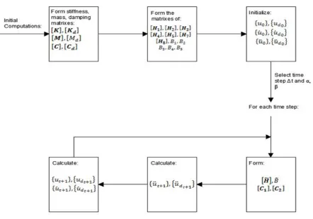
The Newmark-β method [Gavin, 2011] was used to express the displacement and velocity of the primary mass and damper using the following recurrence relations:
= +∆ ̇ +∆ [ − ̈ + ̈ ] (6)
̇ = ̇ +∆[(1− ) ̈ + ̈ ] (7)
= +∆ ̇ +∆ [ − ̈ + ̈ ] (8)
̇ = ̇ +∆[(1− ) ̈ + ̈ ] (9)
Substitute ; ̇ into (4) and ; ̇ into (5)
[ + ∆ + ∆ ] ̈ + ∆(1− ) + ∆ − ̈ + [ + ∆] ̇ +
= − + [ ∆ + ∆ ] ̈
+ ∆ − + ∆( − ) ̈ + [ ∆+ ] ̇ + (10)
or
[ + ∆ + ∆ ] ̈ + ∆(1− ) + ∆ 1
2− ̈
+ [ + ∆] ̇ + = − ( ̈ ) − (11)
The following matrices, H1, H2, H3, H4, H5, H6, H7, and H8 were defined to simplify the computations:
= + ∆ + ∆
= ∆(1− ) + ∆ 1
2−
= + ∆
=
= ∆ + ∆
= ∆ 1
2− + ∆(1− )
= ∆+
=
The matrices H1 thru H8 are all × matrices
The following scalar quantities B1, B2, B3, B4, and B5 were also introduced to simplify the computations:
= + ∆ + ∆
= ∆(1− ) + ∆ 1
2−
= + ∆
=−
Eqn. (10) and Eqn. (11) could be expressed in the following forms:
̈ + ̈ + ̇ + = − + ̈ + ̈ + ̇ + (12)
̈ + ̈ + ̇ + = ( ̈ ) − (13)
Let
= − + ̈ + ̇ + − ̈ − ̇ −
= ̈ + ̇ + +
Eqn. (12) and Eqn. (13) could be expressed as:
̈ − ̈ =
( ̈ ) − ̈ = (14)
The solution given in equations (15) and (16) determines the acceleration time history response of the 2-DOF system and the damper
̈ = ̈̈ = −
− (15)
̈ = ( ̈ ) (16)
Where
= − ; =
Fig. 2: Flow chart of the algorithms of the Matlab code.
3. Application of TMD to 4-Story and 10-Story Building Structures
In this study a single TMD was applied to a low rise and medium rise buildings. The TMD was placed at different levels in these buildings. The effects of TMD mass ratio, = / , TMD damping ratio, =
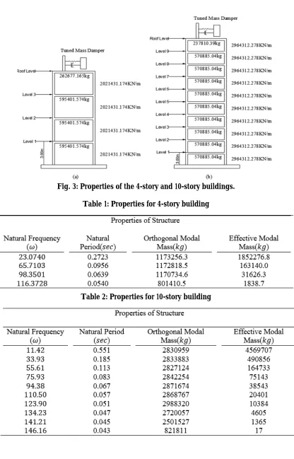
/(2 ), and TMD frequency ratio, = / , were evaluated for different earthquake ground motions. The mass ratio was calculated as the ratio of the mass of the damper to the first mode mass of primary structure calculated as =Φ Φ . The frequency ratio was calculated as the ratio of frequency of damper to the first mode frequency of primary structure. Fig. 3 shows the two structures evaluated in this study.
Fig. 3: Properties of the 4-story and 10-story buildings.
Table 1: Properties for 4-story building
3.1.Response of 4-Story Building Structure to TMD at Various Elevations
The 4-story building structure shown earlier in Fig. 3(a) was subjected to the El Centro ground motion. Two other ground motions (Lexington and Altadena) were also evaluated for comparisons. A single TMD was placed at the 4th level (roof level) and the 3rd level and the roof displacements and base shears were obtained for
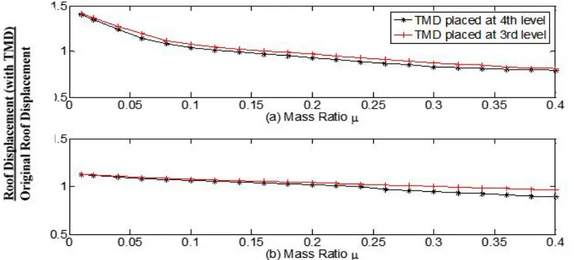
each TMD location. The effect of damping ratio of the first two modes of primary structure was also investigates. Two cases for damping ratios were selected: = = 0.02 and = = 0.05. Figure 4 shows the effect of the TMD mass ratio m on the roof displacements of the 4-story building. The building was subjected to the El Centro ground motion and the TMD was placed on the 4th level (roof level). The system damping of the primary structure
was assumed to be 2%. The vertical axis in Figure 4 is the ratio of the roof displacement with the TMD in place to the original roof displacement (without the TMD). The horizontal axis is the TMD mass ratio defined earlier.
Fig. 4: Reduction in roof displacements with single TMD placed at 4th level and at 3rd level of 4-Story
building damping with damping ratios = 0.02.
The plot in Fig. 4 shows the effect of mass ratio, , on the roof displacement obtained for the El Centro ground motion. The figure shows that the roof displacement decreases as the mass ratio, , increases. Figure 4 shows that for a mass ratio of 10% and damping ratio of 2% ( = 0.1 and = = 0.02), the roof displacement decreases to become 36% of the original displacement (without TMD). In other words, the reduction in roof displacement was about 36%. Similar reduction was observed when the TMD was placed at the 3rd level. Fig. 5
Fig. 5: Reduction in roof displacements with single TMD placed at 4th level and at 3rd level of 4-Story
building damping with damping ratios = 0.05.
Similar trend is found for the roof displacement for the other ground motions (Lexington and Altadena). Fig. 5 also shows that up to a mass ratio of 15% (( = 0.15), the reduction in roof displacement was similar for both locations of the TMD (3rd level or 4th level). However, for mass ratios between 15% and 25%, the reduction was
higher when the TMD was at the 3rd level compared to the 4th level. The effect of the damping ratio of the primary
structure on the roof displacement reduction is shown in Fig. 6. Fig. 6 shows that the reduction in roof displacements for a mass ratio of 10% ( = 0.1) for = 0.05 and = 0.02 is 28% and 36%, respectively. For a mass ratio of 15% ( = 0.15), these reductions were 31% and 40% respectively. This value indicated the effects of the TMD are more pronounced when the structure has lower damping ratios. However, the absolute roof displacement was still lower for the higher damping ratio. For example, the roof displacements were 0.858 in (21.8 mm), and 0.701 in (17.8 mm) for = 0.02 and = 0.05 respectively. With a TMD at 4th level and mass ratio is
= 15%, the roof displacement were 0.518 in (13.2 mm), and 0.483 in (12.2 mm) for = 0.02 and = 0.05 respectively.
Fig. 6: Reduction in roof displacements with single TMD placed at 4th level of 4-Story building damping
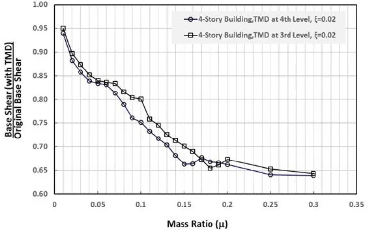
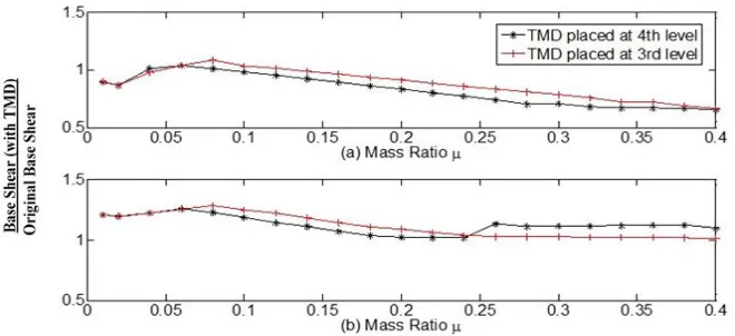
The effect of the TMD on the base shear for the 4-story building is shown in Figs. 7 and 8 for 2% and 5% respectively. Figs. 7 and 8 show the base shear decreases with the increase of mass ratio. It is also observed that the decrease is more pronounced with higher damping ratio. Both figures show that the base shear with TMD placed at 4th level is smaller than that when the TMD is placed at 3rd level for mass ratios less than 20% (< 0.2). It is
observed that the base shear for TMD placed at 4th level is similar to that when the TMD is placed at 3rd level when
the damper mass is larger than 20% of the first mode modal mass of the primary structure.
Fig. 7: Base shear reduction of 4-story structure for two locations of the TMD for damping coefficient of primary structure =0.02.
While one would expect the base shear to increase with additional mass from the damper, the base shear of the system is still lower than the original base shear (without TMD) due the tuning effects of the damper in reducing the inertia forces. When the mass ratio is larger than 20%, there seems to be slight or no further reduction in the base shear. This may be attributed to the additional mass of the damper that contributes to higher inertia forces.
As expected, the base shear decreases with the increase of the damping ratio of the primary structure and the reduction in base shear was higher with higher damping. For example, for a mass ratio of 10% and a damping ratio of 2% ( = 0.1 and = = 0.02), the original elastic base shear was about 4,590 kips (20,415 kN) and the reduction was 25% when the TMD was placed at the 4th level as shown in Fig. 7. When the TMD was placed at the
3rd level the reduction in the base shear was about 20%. Fig. 8 shows that the reduction in the base shear for
Fig. 8: Base shear reduction of 4-story structure for two locations of the TMD for damping coefficient of primary structure =0.05.
With TMD attached at various levels, the base shear reduction when TMD placed at 4th level is higher than
that when the TMD is placed at the 3rd level as shown in Figs. 7 and 8. The higher reduction with the TMD at level
4 may be attributed to the accelerations at the 4th level are lower than those with TMD placed at 3rd level. The
optimal roof displacement reduction, base shear reduction, story drift, optimal damping ratio and optimal frequency ratio are obtained for the El Centro ground motion. The changes in roof displacement and base shears when the building-damper system was subjected to the Altadena and Lexington ground motion are shown in Figs. 9 and 10 respectively. Figs. 9 and 10 show different trends than those observed for the Elcentro ground motion. Fig. 9 shows that the TMD amplifies the roof displacements for the Altadena and the Lexington ground motions when the mass ratio is less than 15% and 25% respectively.
Fig. 10: Effect of damper on base shear of 4-story structure with 2% damping ( = . ) (a) Altadena ground motion; (b) Lexington ground motion.
The TMD also amplifies the base shear if the mass ratio is between 4% and 12% when subjected to the Altadena ground motion. For Lexington ground motion, the added TMD increases the base shear from 2% to 28% for the range of mass ratios shown in Fig. 10. These amplifications in roof displacements and base shears were not observed when the building structure with the TMD was subjected to the El Centro ground motion. These results show that optimum damper properties are dependent on the damper properties and earthquake time history and its characteristics and the TMD may not be well suited to certain structures and certain ground motions. The response of a building-damper system to near field and pulse velocity type time histories needs further evaluation. The effects of near-field ground motions were not evaluated in this study.
3.2.Response of 10-Story Building Structure to TMD at Various Elevations
The 10-story structure shown earlier in Fig. 1(b) is subjected to El Centro ground motion. A single TMD was placed at various levels along the height of the building. Three levels were chosen to evaluate the effect of TMD location: 1) roof level (10th level), 2) the 8th level, and 3) the 6th level. Response parameter such as rood
displacements, base shear and story drifts were compared for each of the three levels for various mass ratios. The effect of the damping ratio of the first two modes, and of the primary structure and the ground motion characteristics were also analyzed similar to the 4-story building in Section 2.
Fig. 11 shows the reduction in roof displacements for various locations of the TMD in a 10-story building with 2% damping subjected to the Elcentro ground motion. The figure shows that when the TMD is placed at the roof level (10th level) and the 8th level, the reduction in roof displacement were similar with slightly more reduction
with the TMD at the roof level. When the TMD location was lower (at 6th level) and a mass ratio = 0.1, the
Fig. 11: Reduction in roof displacements with single TMD placed at various levels of 10-Story building with damping ratios = 0.02.
Fig. 12: Reduction in roof displacements with single TMD placed at 10th level of 10-Story building with
damping ratios = 0.02 and = 0.05
Fig. 13 shows the reduction in base shears for various locations of the TMD. The figure shows that when the TMD is placed at the 8th level, the reduction in base shear was the lowest compared to other locations. Unlike
the displacements, where when the TMD was at the 6th level the displacements were reduced the least, the base
shear is reduced the least when the TMD is at the 8th level as shown in Fig. 13. However, for the mass ratio range
Fig. 13: Reduction in base shears with single TMD placed at various levels of 10-Story building with damping ratios = 0.02.
Fig. 14: Reduction in base shear with single TMD placed at 10th level of 10-Story building with damping
ratios = 0.02 and = 0.05.
The effect of the TMD on roof displacements and base shear of low and medium rise buildings is shown in Figs. 15 and 16 respectively. In Fig. 15, the effect of the TMD placed at roof levels (4th level for the 4-story building
and 10th level for the 10-story building) show similar trends in reducing roof displacements for mass ratios between
6% and 15%. Beyond 15% mass ratio, more reduction in the roof displacements for the 10-story building is observed while less reduction is observed for the 4-story building. Moreover the trend for the 10 story building is observed to be more or less linear reduction while that of the 4-story building has some nonlinearity for certain range of the mass ratio. Fig. 16 shows the effect of the TMD placed at roof levels (4th level for the 4-story building
and 10th level for the 10-story building) on the reduction of base shears. The figure shows similar trends for the
Fig. 15: Reduction in roof displacements with single TMD placed at roof levels of 4-Storyand 10-story buildings with damping ratio = 0.02.
Fig. 16: Reduction in roof displacements with single TMD placed at roof levels of 4-Storyand 10-story buildings with damping ratio = 0.02.
For example, for a mass ratio of 10% (= 0.1) the reduction in the base shear for the 4-story and the 10-story is 25% and 17% respectively. Beyond a mass ratio of 20%, the difference between the two reductions is less than 5%. It is also observed that the reduction curve for the 4-story seems to have a less defined slope compared to the 10-story reduction curves.
Fig. 17: Displacement reduction of roof level of 10-story structure with = . (a) Altadena ground motion; (b) Lexington ground motion.
Fig. 18: Base shear reduction of roof level of 10-story structure with = . (a) Altadena ground motion; (b) Lexington ground motion.
4. Conclusion and Recommendations
A 4-story building and a 10-story building with tuned mass dampers were subjected to various ground motions to evaluate the effect of the TMD on reducing the roof displacement, base shear, and story drifts. Based on results from this study, the following conclusions can be presented:
1. The analytical investigation carried out in this study showed that TMD devices with optimum properties can be selected to reduce roof displacements and base shears in low rise and medium rise buildings subjected to earthquake ground motions.
2. While the reductions in displacements and base shears can be significant, these reductions should be analyzed and viewed relative to magnitudes of displacements and base shears under consideration. These reductions may not justify the use the TMD in low and medium earthquake zones compared to high seismic zones. For strong ground motions, the use of TMD may be a viable alternative compared to other alternatives.
4. The reductions in roof displacements and base shear were higher for buildings with lower damping ratios compared to buildings with higher damping ratios. This is expected since the TMD increases the damping of the system and is more effective in structures with lower inherent damping.
5. The study showed that placing the TMD at higher levels was more effective in reducing displacements and base shear compared to lower levels. This was more pronounced in the low rise 4-story building compared to the 10-story building.
6. These results show that optimum damper properties to mitigate seismic forces are dependent on the earthquake time history and its characteristics as well as the damper properties; the TMD may not be well suited to mitigate the seismic response for certain ground motions as observed in this study. In such cases other mitigation measures should be considered.
7. The effect of multiple TMD’s placed at various elevations and the effect of TMD on the response of higher modes as well as and the effects near field ground motions were not analyzed in this study.
References
Abdel-Rahman M, Leipholz HHE. (1979). General approach to active structural control. Journal of Engineering
Mechanics Division, ASCE105(6): 1007–1023.
Den Hartog, (1985) Mechanical Vibrations (4th ed.), McGraw-Hill, New York, 1956. (Reprinted by Dover, New York, 1985).
Gavin, H. (2001). Numerical integration for structural dynamics. Department of Civil and Environmental Engineering,
Duke University, Durham, NC.
Gupta Y.P., and Chandrasekaren, (1969) “Absorber systems for earthquake excitations” Proceed of the 4th International
Conference on Earthquake Eng, Vol. II, Santiago, Chile, pp. 139-148. HancockTower Now to Get Dampers, Engineering News Record, 11 (1975).
James Chang CH, Soong TT. (1980). Structural control using active tuned mass dampers. Journal of Engineering
Mechanics Division, ASCE 106(6): 1091–1098.
Kaynia, A. M., Veneziano, D., and Biggs, J. M. (1981). “Seismic effectiveness of tuned mass dampers.” J. Struct. Eng., 107(8), 1465– 1484.
Matta, E., (2013),‘Effectiveness of Tuned Mass Dampers against Ground Motion Pulses’, ASCE Journal of Structural Engineering.
Miyama, T. (1992). “Seismic response of multi-story frames equipped with energy absorbing story on its top.” Proc., 10th World Conf. on Earthquake Engineering, Vol. 7, Balkema, Rotterdam, Netherlands, 4201–4206. Rana, R., & Soong, T. T. (1998). Parametric study and simplified design of tuned mass dampers. Engineering structures, 20(3),
193-204.
R. J. McNamara, (1977). Tuned mass dampers for buildings. J. struct. Div. ASCE 103, 1785-1798. R. W. Clough, Joseph Penzien. (1993). Dynamics of structures, McGraw-Hill, New York. R.W. Luft. (1979). Tuned mass dampers for buildings. J. Struct. Div. ASCE 105, 2766-2772.
Sadek,F., Mohraz, B., Taylor, A., and Chung, R. (1997), “A Method for estimating the parameters of tuned mass dampers for seismic applications,” Journal of Engineering Engineering and Structural Dynamics, Vol. 26, pp. 617-635.
Sladek, J. R., and Klingner, R. E. (1983). “Effect of tuned mass dampers on seismic response.” J. Struct. Eng., 109(8), 2004–2009.
Soong TT. (1990). Active Structural Control: Theory and Practice. John Wiley: New York.
Tuned Mass Dampers Steady Sway of Sky Scrapers in Wind, Engineering News Record, 28-29 (1977).
Villaverde, R. (1994) “ Seismic Control of Structures with Damped Resonant Appendages’, Proceed of the 1st World Conference on
Structural Control, LA, California, pp. 113-119.
Villaverde, R., and Koyama, L. A. (1993) “Damped Resonant Appendages to Increase Inherent Damping in Buildings’,
Earthquake Engineering Structures, 22, pp. 491-507.
Wirsching, P.H., and Yao, J. T.P., (1973) “Safety design concepts of seismic structures” , Journal of Computers and