Developing of Industry 4.0 Applications
https://doi.org/10.3991/ijoe.v13i10.7331Juan David Contreras!!",Jose Isidro Garcia, Juan David Pastrana Universidad del Valle, Cali, Colombia
Abstract—The fourth industrial revolution, or industry 4.0, has recently be-come an important topic in the manufacturing context. This standard-based strategy integrates Smart Factories, Cyber-physical Systems, the Internet of Things, and the Internet of Service with the aim of extending the capacity of manufacturing systems. Although several authors have presented the ad-vantages of this approach, few papers refer to an architecture that allows the correct implementation of industry 4.0 applications using the guidelines of the reference architecture model (RAMI 4.0). This article exposes the essential characteristics that allow a manufacturing system to be retrofitted to become an industry 4.0 application. Specifically, an intelligent manufacturing system based on a holonic approach was developed and implemented using standards like FDI, AutomationML and OPC UA according to the RAMI 4.0 model.3
Keywords—Industry 4.0, smart factories, RAMI 4.0.
1
Introduction
Considering industry is a core element of the value chain and a crucial component in the technological development, job creation and economic stability of a country [1], the traditional industrialized countries have assumed a leading role in the fourth industrial revolution, or Industry 4.0, as a strategy to confront new requirements in the global market and position themselves more competitively against emerging countries [2]. This strategy has been planned to offer new potential to the manufacturing indus-try such as meeting individual customer requirements, optimizing decision-making and adding new product capacities [3].
A well supported definition of industry 4.0 is presented by Hermann in [4] as: “In-dustrie 4.0 is a collective term for technologies and concepts of value chain organiza-tion. Within the modular structured Smart Factories of Industrie 4.0, Cyber-Physical Systems (CPS) monitor physical processes, create a virtual copy of the physical world and make decentralized decisions. Over the IoT (Internet of Things), CPS communi-cate and cooperate with each other and humans in real time. Via the IoS (Internet of Services), both internal and cross-organizational services are offered and utilized by participants of the value chain”.
3) the Internet of Things, and 4) the Internet of Service. Next, a more detailed descrip-tion of each item is given as follows.
Several definitions have been presented for the Smart Factories, according to [3] "Smart Factories are a key part of Industry 4.0. In these systems, humans, machines and resources communicate with each other, naturally emulating a social network." According to [5], factories develop intelligent control autonomously through intelli-gent elements using holistic digital manufacturing and production models. According to [4], an intelligent factory can be defined as a factory where CPS communicate through the IoT and assist people and machines in the execution of their tasks.
Generally, CPS can be defined as systems that link the cyber world of computing and communication with the physical world [6]. According to [7], CPS are embedded in software systems in which:
• They record data directly using physical sensors and perform physical processes
using actuators.
• Evaluate and keep recorded data, and actively or proactively interact with both the
physical world and the digital.
• Are connected to each other and to global networks through digital communication facilities (wireless and / or wired local and / or global)
• They use globally available data and services.
• They have a series of dedicated, multimodal, human-machine interfaces.
The IoT refers to the network interconnection of everyday objects [8]. One of the objectives of the IoT is that objects interact with each other and cooperate with neigh-boring components to achieve common goals [9]. According to [10], in the context of industry 4.0, the IoT serves to integrate the CPS in production and logistics end to end.
The IoS has the vision to enable service providers to offer services via the Internet [11]. According to [12], “in industry 4.0, the CPS, the hardware and software are represented as services" this way of conceiving the elements "allows a new form of dynamic variation distribution in individual activities of the value chain" [13].
Using the IoS in industry 4.0 implies that the elements of the value chain adopt a service-oriented architecture (SOA), which requires a platform for networking and a series of layers in each element than can be accessed as services from other elements.
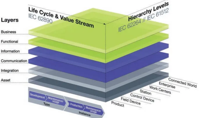
Technology trends presented before have been widely developed individually but integrated in the context of Industry 4.0. This integration has been planned to be based on existing standards, approaches and methods, which are represented in a three-dimensional model where each axis represents an aspect in the Industry 4.0 context. This model is known as “Reference Architecture Model Industrie 4.0” (RA-MI4.0) which was presented by the VDI/VDE Society for Measurement and Auto-matic Control (GMA) in 2015 as a reference to “permits step by step migration from the world of today to that of I4.0, and the definition of application domains with spe-cial stipulations and requirements”[14].
Fig. 1. Reference Architecture Model Industrie 4.0 (RAMI4.0)
based in the IEC 62890 standard. In the right-hand horizontal axis, the roles and re-sponsibilities within the factory or plant are represented; this composition represents a functional hierarchy based on the IEC 62264 standard but adding the elements “Con-nected World”, “Field Device” and “Product” to extend the standard to the functional-ities of Industry 4.0.
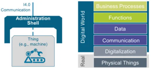
RAMI 4.0 includes the definition of the Industry 4.0 Component (I4.0 Compo-nent), which aims to describe in more detail the properties that CPS must meet in Industry 4.0 [15]. Also, the “administration shell” is described as a key element, which turns an object or asset into an I4.0 Component [16] enabling storage of prop-erties and states in the virtual world and the ability to share this data with other com-ponents through I40 complaint communication. In Figure 2, an example of an I4.0 Component, shows the integration of an asset (Machine) with its Administration Shell. This example illustrates that the administration shell is the element where the communication layer, information layer, functional layer and business layer are de-ployed [17].
Although RAMI 4.0 represents a cornerstone for the development of projects in in-dustry 4.0, it is only focused on the definition of rules for the implementation of I4.0 applications on a high level point of view, and knowing that each manufacturing sys-tem requires a different, special development according to their specific requirements. Therefore, it is necessary to integrate the RAMI4.0 with other strategies to reach a complete I4.0 application development.
Fig. 2. The I4.0 Component as a composition of asset and administration shell
system architecture but do not integrate the standards such as in [20, 21, 22] where they propose the use of AutomationML and OPC UA as future work. Finally, there are projects which define a system architecture and integrate some standard such as in [23] which only use OPC UA. As a response to this lack of integration between the development of I4.0 applications and the standards of the RAMI 4.0, this article inte-grates the proposal of a system architecture for product-driven manufacturing with some standards of the RAMI 4.0 for system deployment, using OPC UA for the im-plementation of the communication layer, FDI for the information and functional layer, and AutomationML for the end-to-end engineering. This integration is present-ed in an application example.
The next sections of this article presents a proposal for the development of a I4.0 application including the initial system architecture, followed by the dynamic behav-ior and roles of each element of the system defined by a holonic, multi-agent ap-proach. Finally, the structure and dynamic proposal is integrated to the RAMI4.0 implementation rules.
2
Architecture for I4.0 Applications
In this section, a general architecture that allows the execution of product-driven manufacturing for industry 4.0 is presented. First, the core elements needed by the architecture are determined and, subsequently, the relationships between the elements are defined and finally a model of the architecture and its interactions is presented.
2.1 Implementation restrictions
As expressed in section I, RAMI4.0 is focused on the definition of rules for the implementation of I4.0 applications. This means the applications must follow the restrictions presented in RAMI 4.0 to fulfill the established standards.
2.2 Holonic representation of the I4.0 Application
An I4.0 system can be described as the integration of I4.0 Components, which have the following properties:
• The components of the same level can interact and cooperate with each other to
meet common and individual goals.
• Each component may be composed by other components of a lower level and be a
part of a higher lever component (i.e.logical nestability property of I4.0 Compo-nents)
• All have the same fundamental internal structure but with different roles.
These properties are similar to the concept of a holon and holarchy presented in [25], this means, an I4.0 system can be represented as a holarchy composed of I4.0 Components as the holons. Therefore, the architecture of I4.0 systems can be devel-oped by following the architecture of the holonic manufacturing system (HMS).
Typically, the holons are implemented using intelligent agents to accomplish the logic functionality, in the context of this article, the term agent or intelligent agent refers to a entity able to perceive their environment, process such perceptions and respond or act in their environment in a rational way. The rationality of the artificial agent is implemented in an agent program that maps perceptions to actions and is designed using artificial intelligence (AI). This agent program runs on a computing device, which is called the architecture of the agent. A set of agents that cooperate to achieve a common goal is called a multi agent system (MAS).
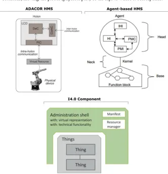
Firstly, it has been found that some HMS architectures have internal holon repre-sentation similar that the internal structure of the I4.0 Component (Figure 2). In Fig-ure 3, the contrast between the I4.0 Component and holons of two HMS architectFig-ures are presented. The first HMS is known as ADACOR (ADAptive holonic COntrol aRchitecture) [26] and the second is an agent-based HMS [27]. As can be seen, both architectures have a virtual component associated to a physical resource, just as the administration shell is associated to the asset in the I4.0 Component. According to this structure and following the requirements of the RAMI 4.0, the holon’s logic can be performed by an agent in charge of managing, publishing and providing services, and it can be deployed as part of the functional layer [28].
Then, the relationships between the elements is established by defining the roles of each holon to accomplish a desired functionality. In a manufacturing system, the function of the system is to produce a transformation from material to products in order to generate added value. Considering this, an adaptation of holon's roles defined in PROSA (Product-Resource-Order-Staff Architecture) [29] and ADACOR HMS are proposed defining three types of holons:
1.Resource Holon (Hr): Which represents each process resource such as machines, robots, CNC, stations, warehouses or transport elements. The Hr is composed of both the physical component (hardware) and the control component (software). 2.Product Holon (Hp): Which represents each intelligent product or matter that has
to complete its transformation according to the requirements of the client, and share it with other holons.
3.Coordinator Holon (Hc): Which represents a computational element able to request the state of the holons and evaluate the best sequence available processes to com-ply with the transformation of the Hpr using the available Hr. The computational system is integrated to a transport system that is in charge of applying the made decisions, moving the pieces (physical part) of the Hpr to where it corresponds.
Fig. 3. HMS Holon internal structure and the I4.0 Component.
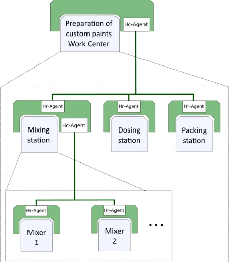
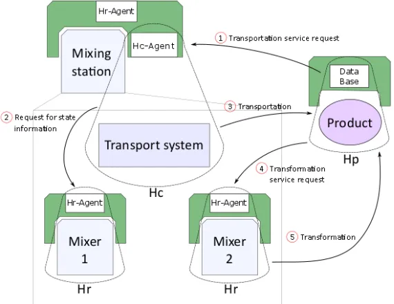
The implementation of this dual functionality is perform using agents as show in Figure 4, where the I4.0 Components composing a work center in charge of the prepa-ration of custom paints is represented. In this example, the administprepa-ration shell of the mixing station is nested to the work center and contains a Hr-agent that responds to Hr reactive logic as part of its functional layer. The same station also contains two mixers, which are managed using a search algorithm performed by the Hc-agent of the station, which is deployed in its functional layer.
As mentioned before, for a I4.0 Component, both the Hr-agent and the Hc-agent can be part of the functional layer to be according to [14], where it specifies that deci-sion-making logic is generated inside the functional layer. Despite that, there are differences between the agents. The decision-making logic in the Hr-agent corre-sponds to reactive planning algorithms that manage the services in the functional layer. This is provided directly by the asset through an assessment of the request and it decides the service, or sequence of services that should be provided. On the other hand, the decision-making logic in the Hc-agent corresponds to a search algorithm which manages the services in the functional layer that can be provided by the logi-cally nested I4.0 Components. This search algorithm evaluates the components’ state in real-time and selects the component that should provide the service. In other words, the Hr-agent responds to a service request when there is a single provider (the asset) and the Hc-agent responds to a service request when there are several providers (the nested I4.0 Components).
The Hp can be active or passive depending of the capacities of the smart product or material. In the case of a material capable of only storing data locally (e.g. with a RFID tag), it can require the services of Hr or Hc by sharing an ID (identification) and then de agents will search for the respective manufacturing plan in a database or re-pository. If the material has processing and communication capabilities, it will be able to request the corresponding service directly from the Hc or Hr. To make this possi-ble, the Hp must be uniquely identifiable and have a data base associated locally or in a remote repository. According to RAMI 4.0, the products can be represented as I4.0 Components and also have its own Administration Shell.
2.3 Interaction between components
As presented in the previous section, the interaction between the holons is per-formed using a service orientation approach. To be considered as an application, I4.0 should be implemented following the RM-SA [24]. The detailed description of the set of services defined in RM-SA is out of the scope of this article, but a set of proposed services user/providers interactions for product-driven manufacturing is presented below.
In Figure 5, a sequence of interactions between the holons is presented. In this rep-resentation, the composition of the mixing station in Figure 4 is detailed and the Hp is added. The holons are represented as the integration of a physical and virtual compo-nent. The physical components are the mixers, the transport system and the product, and the virtual components are the Hr-agent, the Hc-agent and the data base for the Hr, Hc, and Hp respectively.
First, interaction 1 is a request from the Hp to the Hc for a transportation service; this request is performed between virtual components but triggered by an event be-tween the physical components. Interaction 2 is a request of state information from the Hc to the Hr, this information is used by the HC-agent to feed the search algo-rithm and decide the target Hr in the transportation. Interaction 3 is the response of the Hc to the request of the Hp providing the transportation service. This step involves a physical interaction between the transport system and the product. After the trans-portation, interaction 4 occurs, where the arrival of the product to the resource triggers a request of transformation services from Hp to Hr. To respond to this request, the Hr-agent evaluates the transformation required (manufacturing process) using the reac-tive planning algorithm and the process finishes with interaction 5 applying the physi-cal transformation to the product. Finally, the Hr delivers the product to a correspond-ing transport system, in this example, to the packcorrespond-ing station (Figure 4).
3
Implementation Procedures
As an application example, the system presented in the Figure 5 (mixing station) is implemented following the RAMI 4.0 guidelines. The mixing station is an electro-pneumatic didactic system and is part of the Laboratory of Mechatronics in the Uni-versidad del Valle, the system is shown in Figure 6.
3.1 Standards and resources for the implementation based on the RAMI 4.0. The standards and the tools chosen for the implementation of the components of the RAMI 4.0 are presented next:
Integration layer; the integration layer is implemented using a Raspberry Pi 3[30]
and a Codesys ® Emulator [31] to deploy the control algorithm and integrate the virtual world with the physical world by reading the sensors and controlling the actua-tors.
Communication layer; the RAMI 4.0 specifies OPC UA (IEC 62541 standard)
[32] as the only approach for this layer. For the deployment of the OPC UA servers and client, open62541 is used. This is an open source C (C99).
Information and functional layer; the Field Device Integration (FDI) standard
(IEC 62769 standard) [33] was selected as the approach for the implementation of these two layers, this FDI standard uses the Electronic Device Description Language (EDDL) to specify the parameters and functionality of the device [34]. The FDI Pack-age information can also be easily mapped to the OPC UA information model using the mapping rules describe in [35][36].
End-to-end engineering; the most used and well supported standard for the
im-plementation of the end-to-end engineering as part of the information layer has been AutomationML (Automation Markup Language), which is standardized in IEC 62714 [37]. Several articles have been published presenting the combination of Automa-tionML and OPC UA as an ideal approach for meeting interoperability during the engineering phase [38][39][40]. This standard integrates other standards like CAEX, COLLADA and OpenPLC, which aids the interchange and visualization of engineer-ing data like geometry, kinematics and control flow. For this application example, an AutomationML representation of the mixer station is developed using the Automa-tionML Editor tool, then, the mapping to the OPC UA information model is per-formed using the mapping rules described in [41].
3.2 Procedure for accomplishing interoperability between the I4.0
Components
Fig. 7. Roles and relationships between OPC UA, FDI and AutomationML.
In the Figure 8, a proposed procedure for managing information on both the client and server side is presented. On the server side, three functions are defined; first, the information is restructured to FDI and AutomationML format resulting in the corre-sponding XML files, then, these files are mapped to the OPC UA information model using the mapping rules resulting in a XML definition of the address space, finally, the OPC UA server plush the information importing the XML.
On the client side, the first function is in charge of browsing or discovering the cor-responding server, then, a second function browses for the desired information ac-cording to the mapping rules inside the server, finally, the information is structured in a FDI or AutomationML format and saved or used for the client side component.
Figure 8 also shows that all functions, both server and client side, use a common know semantic. This semantic is provided by the standards and represents a key ele-ment for the interoperability in an I4.0 System.
3.3 Application example implementation
In this section, the previous standards, tools and procedures are applied to the mix-ing station in Figure 6 accordmix-ing to the procedure of the Figure 8.
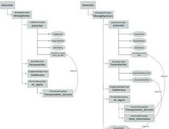
Implementation of the information and functional layer using FDI. Figure 9
shows the DeviceSet component of the FDI representation for the mixing station and a mixing machine (Mixer 1). The internal component of the mixing station and the mixing machine are including in the SubDevice object of each device.
Fig. 9. FDI representation of Mixing station and Mixing machine 1.
As can be seen, the transport service called Move_to_Mix of the mixing station and the transformation service called Mix in the mixing machine are components of the ActionSet object of each device. This object is responsible for providing the services (actions) through the InvokeAction method, which, from an event in the communica-tion layer (method call), creates an event in the informacommunica-tion layer that is linked to a service in the functional layer thereby meeting the requirement in RAMI4.0 that sets that events may only be exchanged between two adjacent layers and within each lay-er.
The Hc-Agent and the Hr-Agent are represented in the FDI information mod-el as a functional group element that for the case of the mixing station nests the Transportation_Services functional group, which refers an organize reference to the
group nests the Transformation_Services functional group, which refers an organize reference to the Mix action in the ActionSet. Additionally, it includes a
State_Information functional group that organizes variables and parameters that can
be required by the Hc-Agent to make decisions or resolve conflicts. This way of de-fining the agents allows users to search for functional groups that are identical to all devices and find the corresponding transportation or transformation services that are particular of each device.
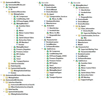
Representation of the system using AutomationML is developed using the
Au-tomationML Editor, where a complete representation of the system using Automa-tionML standard is permitted. Figure 10 shows the developed model. This representa-tion can be used in several applicarepresenta-tions like design, maintenance, and 3D visualiza-tion using COLLADA attached files.
Fig. 10.AutomationML representation of the mixing machine.
Mapping to OPC UA information model and publication in server applying the
mapping rules to the models of the Figure 9 and 10. This task can be done manually using OPC UA modeling tools, however, if the system is complex this can be tedious and lead to errors. Because of this, the development of tools for automatic generation of XML address space from the models of FDI and AutomationML in XML format is recommended.
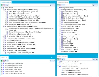
is used to browse and visualize the server address space. In Figure 11, the resulting address spaces of the AutomationML and FDI representation of the mixing station and the FDI representation of the mixing machine 1 are presented.
Fig. 11. Servers address space for the mixing station and mixing machine.
Implementation of the Hp is performed considering that the physical products are
4
Conclusion
The use of a standard-based reference architecture as a cornerstone for the imple-mentation of industry 4.0 applications allowing researchers to guarantee interoperabil-ity between systems even if they have been developed using different approaches and are geographically dispersed. This allows both horizontal and vertical integration of the smart factories to be accomplished, and the development of scalable solutions.
In this article, it was demonstrated that a traditional manufacturing system can be retrofitted to meet the requirements of industry 4.0 without having to change all the technology within the system. By adding a virtual representation through the admin-istration shell and using standardized tools for the implementation of specific domine strategies, such as the HMS in this article, this approach may allow the system to perform not only intelligent manufacturing, but also to extend its performance to include tools of data analysis, intelligent logistics, and maintenance using a service oriented architecture.
In the proposed architecture, theories and models of MAS and HMS are used which, despite being developed for almost two decades, are not widely implemented in manufacturing systems. In part this lack is due to the fact that these types of sys-tems involve multiple technological requirements in fields such as communication, computing, interoperability and information management. However, as can be seen in this article, the technologies and standards that compose the industry 4.0 aid the im-plementation of these theories and allow the re-configurability of manufacturing sys-tems to be addressed.
According to [42], one of the main weaknesses of software engineering methods for intelligent manufacturing systems is the lack of standardization for implementa-tion, communication protocols and control. In response to this, this project demon-strates the potential that Industry 4.0 has to provide a standardized implementation framework in which different intelligent manufacturing applications can be devel-oped. In the particular case of this project, a HMS was implemented using the stand-ards defined in RAMI 4.0 for the communication and representation of information and functions.
5
References
[1] K. Linsu, “Stages of development of industrial technology in a developing country: A model,” Res. Policy, 2002.
[2] M. Blanchet, T. Rinn, G. Von tharden, and G. De Thieulloy, “Industry 4.0 The new industrial revolution how europe will succeed,” Think Act, 2014.
[3] H. Kagermann, W. Wahlster, and J. Helbig, “Recommendations for implementing the strategic initiative INDUSTRIE 4.0,” 2013.
[4] M. Hermann, T. Pentek, and B. Otto, “Design Principles for Industrie 4.0 Scenarios: A Literature Review,” 2015.
[6] R. Rajkumar, L. Imsup, L. Sha, and J. Stankovic, “Cyber-Physical Systems: The Next Computing Revolution,” Des. Autom. Conf., 2010.
[7] acatech (Ed.), “Cyber-Physical Systems. Driving force for innovation in mobility, health, energy and production (acatech POSITION PAPER),” Heidelb. Springer Verlag, 2011. [8] F. Xia, L. T. Yang, L. Wang, and A. Vinel, “Internet of Things,” Int. J. Commun. Syst.,
2012.
[9] D. Giusto, A. Iera, G. Morabito, and L. Atzori, “The Internet of Things,” 2010.
[10] S. Heng, “Industry 4.0 Upgrading of Germany’s industrial capabilities on the horizon,” 2014.
[11] P. Buxmann, T. Hess, and R. Ruggaber, “Internet of Services,” Bus. Inf. Syst. Eng., vol. 5, 2009.
[12] M. A. Pisching, F. Junqueira, D. J. Santos Filho, and P. E. Miyagi, “Service Composition in the Cloud-Based Manufacturing focused on the Industry 4.0,” in Technological Innovation for Cloud-Based Engineering Systems, Springer International Publishing, 2015, pp. 65–72.
[13] Plattform Industrie 4.0, “Industrie 4.0 - Whitepaper FuE Themen,” 2013. [Online]. Available: http://www.plattformi40.de/sites/default/files/Whitepaper_Forschung Stand 3. April 2014_0.pdf.
[14] P. Adolphs, H. Bedenbender, and D. Dirzus, “Reference Architecture Model Industrie 4.0 (RAMI4.0),” 2015.
[15] M. Hoffmeister, “Industrie 4.0: The Industrie 4.0 Component,” 2015.
[16] P. Adolphs, S. Auer, H. Bedenbender, M. Billmann, M. Hankel, R. Heidel, M. Hoffmeister, H. Huhle, and M. Jochem, “Structure of the Administration Shell Continuation of the Development of the Reference Model for the Industrie 4.0 Component,” 2016.
[17] Plattform Industrie 4.0, “Reference Architectural Model Industrie 4.0 (RAMI 4.0) An Introduction.” 2016.
[18] F. Baena, A. Guarin, J. Mora, J. Sauza, and S. Retat, “Learning Factory!: The Path to Industry 4 . 0,” in Procedia Manufacturing, 2017, vol. 9, pp. 73–80.
[19] E. Marilungo, A. Papetti, M. Germani, and M. Peruzzini, “From PSS to CPS design!: a real industrial use case toward Industry 4 . 0,” Procedia CIRP, vol. 64, pp. 357–362, 2017. [20] J. Wan, M. Yi, D. I. Li, C. Zhang, S. Wang, and K. Zhou, “Mobile Services for
Customization Manufacturing Systems!: An Example of Industry 4 . 0,” pp. 8977–8986, 2017.
[21] S. Weyer, T. Meyer, M. Ohmer, S. Dominic, T. Meyer, M. Ohmer, S. Dominic, T. Meyer, M. Ohmer, and D. Gorecky, “Future Modeling and Simulation of CPS-based Factories!: Future Factories!: Future Factories!: Example from the Automotive Industry Future an Factories!: an Example from the Automotive Example from the Automotive an Example from the Automotive Industry,” IFAC Pap., vol. 49, no. 31, pp. 97–102, 2016.
[22] I. Grangel-gonzález, L. Halilaj, S. Auer, S. Lohmann, C. Lange, and D. Collarana, “An RDF-based Approach for Implementing Industry 4 . 0 Components with Administration Shells,” IEEE Access, 2016.
[23] M. Hoffmann and C. Büscher, “Continuous Integration of Field Level Production Data into Top-level Information Systems Using the OPC Interface Standard,” Procedia CIRP, vol. 41, no. February, pp. 496–501, 2016.
[24] T. Bangemann, C. Bauer, H. Bedenbender, and A. Braune, “Industrie 4.0 Service Architecture Basic concepts for interoperability,” 2016.
[26] P. Leitão and F. Restivo, “ADACOR: A holonic architecture for agile and adaptive manufacturing control,” Comput. Ind., vol. 57, no. 2, pp. 121–130, 2006.
[27] S. M. Deen, Agent-Based Manufacturing Advances in the Holonic Approach. Springer Berlin Heidelberg, 2003.
[28] E. Legnani, S. Cavalieri, and P. Gaiardelli, “Towards Self-organized Service-oriented Multi-agent Systems,” in Service Orientation in Holonic and Multi Agent, vol. 472, 2013, pp. 71–84.
[29] H. Van Brussel, J. Wyns, P. Valckenaers, L. Bongaerts, and P. Peeters, “Reference architecture for holonic manufacturing systems: PROSA,” Comput. Ind., vol. 37, no. 3, pp. 255–274, 1998.
[30] Raspberry Pi Foundation, “Raspberry Pi Hardware,” 2017. [Online]. Available: https://www.raspberrypi.org/documentation/hardware/raspberrypi/ [Accessd: 21- Jun- 2017]
[31] 3S-Smart Software Solutions GmbH, “CODESYS Control for Raspberry Pi SL,” 2016. [Online]. Available: https://store.codesys.com/codesys-control-for-raspberry-pi-sl.html [Accessd: 21- Jun- 2017]
[32] “IEC TR 62541-1:2016”, IEC Standard, 2016.
[33] “IEC 62769-1:2015 Field device integration (FDI) - Part 1: Overview,”, IEC Standard, 2015.
[34] FDI Cooperation, “FDI Technical Specification Part 1!: Overview,” 2014.
[35] FDI Cooperation, “FDI Technical Specification Part 5!: FDI Information Model,” 2014. [36] “IEC 62769-5:2015 Field Device Integration (FDI) - Part 5: FDI Information Model,”, IEC
Standard, 2015.
[37] “IEC 62714-1:2014 Engineering data exchange format for use in industrial automation systems engineering - Automation markup language - Part 1: Architecture and general requirements,”, IEC Standard,2014.
[38] R. Henßen and M. Schleipen, “Interoperability between OPC UA and AutomationML,” Procedia CIRP, vol. 25, pp. 297–304, 2014.
[39] M. Schleipen, E. Selyansky, R. Henssen, and T. Bischoff, “Multi-level user and role concept for a secure plug-and-work based on OPC UA and AutomationML,” in 2015 IEEE 20th Conference on Emerging Technologies Factory Automation (ETFA), 2015, pp. 1–4. [40] C. Kühnert, M. Schleipen, M. Okon, R. Henßen, and T. Bischoff, “A Modular Architecture
for Smart Data Analysis using AutomationML, OPC-UA and Data-driven Algorithms,” in Machine Learning for Cyber Physical Systems: Selected papers from the International Conference ML4CPS 2016, J. Beyerer, O. Niggemann, and C. Kühnert, Eds. Berlin, Heidelberg: Springer Berlin Heidelberg, 2017, pp. 25–33.
[41] AutomationML consortium, “AutomationML Whitepaper: OPC Unified Architecture Information Model for AutomationML,” 2016.
6
Authors
Juan David Contreras is a mechanical engineer with an M.Eng. from Universidad
del Valle in Cali, Colombia. He works as an adjunct professor in the same university and is currently developing research in Industry 4.0.
Jose Isidro Garcia is a mechanical engineer with an M. Eng, and a Ph.D. from the
Polytechnic School of the University of São Paulo, Brazil. He is a titular professor at Universidad del Valle.
Juan David Pastrana is a senior in mechanical engineering at Universidad del
Valle, Colombia. He has been a teaching assistant of the mechatronics course and is interested in automation focusing on smart factories.