Research Journal
Volume 11, Issue 2, June 2017, pages 33–37
DOI: 10.12913/22998624/69418 Research Article
ANALYSIS OF THERMAL PROPERTIES AND HEAT LOSS IN CONSTRUCTION
AND ISOTHERMAL MATERIALS OF MULTILAYER BUILDING WALLS
Arkadiusz Urzędowski1, Dorota Wójcicka-Migasiuk1, Joanna Styczeń2
1 Lublin University of Technology, Fundamentals of Technology Faculty, ul. Nadbystrzycka 38, 20-618 Lublin,
e-mail: a.urzedowski@pollub.pl, d.wojcicka-migasiuk@pollub.pl
2 Lublin University of Technology, Civil Engineering and Architecture Faculty, ul. Nadbystrzycka 38, 20-618
Lublin, e-mail: j.styczen@pollub.pl
ABSTRACT
The article discusses the impact of vertical partition, technology on thermal insulation of the building, and the resulting savings and thermal comfort of residents. The study is carried out as an analysis of three selected design solutions including such materi-als as: aerated concrete elements, polystyrene, ceramic elements, concrete, mineral plaster. Simulation results of heat transfer in a multi-layered wall, are subjected to a detailed analysis by means of thermal visual methods. The study of existing struc-tures, helped to identify the local point of heat loss by means of infrared technology leading to determination of U-value reduction by 36% in maximum for the described 3 types of structure.
Keywords: thermal insulation, heat transfer coefficient, thermography, building ma -terials, low-energy houses.
INTRODUCTION
In connection with the constant need to reduce
the heat transfer coefficient of building envelope
resulting from changes in legal regulations, man-ufacturers of insulation materials compete with each other in more and more advanced solutions. They aim to introduce new products, or to modify the structure and thermal properties of the exist-ing ones, in a way to minimize unwanted heat loss [1, 3, 4]. It is possible to achieve this task by
careful modification of the type of insulation, the
thickness of the structure, moisture content, type of heat exchange, etc.
A way bulkhead insulation, plays a very im-portant role in the reduction of energy consump-tion. In this work, we attempt to answer the ques-tion - which of the selected soluques-tions, can provide thermal parameters desirable for passive houses and low energy, without unduly increasing the
thickness of the structure. For this purpose, the calculation was carried out within the heat
trans-fer analysis and the advantage of heat flow. The
analysis was carried out for three selected sys-tems of structural exterior walls. The analysis is based on a comparison of the processes occurring in the vertical systems made by means of three technologies. The Complex mechanism of heat exchange though advanced layer structures has not been fully described yet. A comparative anal-ysis, however, can help to understand and point out the most important factors determining the process of heat exchange in vertical wall struc-tures in buildings.
Thermal dynamic of heat transfer may take place by convection, conduction and radiation. However, in practice it can be presented to-gether, leading to the phenomenon of combined heat transfer or its acquisition. Heat acquisition
occurs between a fluid and a solid, of different
temperatures [10]. The complexity of this pro-cess consists of heat conduction through a fluid
layer at the surface of the material and the
con-vection occurring in the fluid. The heat transfer takes place between two fluids of different tem -peratures, separated by a wall and the process consists of a sequence of acquisition, conduction and re-acquisition. This phenomena occur in the complex structures of buildings.
The mechanism of heat conduction is described
by Kirchoff - Fouerier law [8], which has the form:
] ) ( [ 1 )
(
q
c
vp
T T
w t
T ⋅ ∇ ⋅∇ +
⋅ = ⋅ ∇ ⋅ + ∂ ∂
λ ρ
(1)
In this form, the solution of equation can be determined only by approximate numerical methods [5]. However, assuming the value of individual equation component amounts to zero as follows:
• the temperature field does not depend on time ∂T/∂t = 0
• there is no internal heat source qv = 0
• there is no convection (w⋅∇)⋅T =0
One can get the equation for steady during the state assuming the conduction without internal heat sources:
(2) which can be stored in Cartesian coordinates as:
(3) after the transformation one can get the for-mula for proper conduction resistance:
(4)
where: δ - thickness of the wall (m), λ - thermal conductivity of the material (W/mK)
The paper considers a steady conduction through a multilayer wall structure composed of a flat baffle of n-layers and of different thickness. The values of the heat transfer coef-ficients are independent on temperature (i.e..
λ = const). In the simplified method, one can
assume that the structure is made of homoge-neous materials.
For the flat wall, the value of the heat flux q flowing through the structures can be expressed
by means of the following formula:
(5)
where:
(6)
δ1, δ2,…, δi – width of successive layer in the
baffles (m)
λ1, λ2, …, λi – heat transfer coefficients of the suc
-cessive layers (W/mK)
Tw1, Tw2, …, Twi – the temperature of the heat transfer partition successive layers (K)
Hence the definition of heat transfer coefficient U:
(7)
METHODS
In this work, the analysis included three con-struction systems of external walls - two per-formed in traditional technologies and the innova-tive one called the permanent formwork system. Among so many solutions available on the mar-ket, the author select the two most popular tech-nologies of building walls: the ceramic and the el-ements of aerated concrete. The walls constructed with these materials are double-layer - the inner side of structural layer, and on the outside - ther-mal insulation made of expanded polystyrene.
Calculations and simulations have been formed also for innovative technology of per-manent shuttering, which is gaining a wider and wider group of followers. This technology allows for a triple construction. They consist of concrete, surrounded with extruded polystyrene on both sides that has a good thermal insulation param-eters. The calculation is based on the total thick-ness of the divisions of 36,5 cm.
Calculations of heat transfer coefficient have
been performed on the basis of formulas (5-7). System No. I – system composed of the aer-ated element [250×249×373 mm] insulaer-ated with panels of expanded polystyrene of 100 mm
thick-ness, fixed by means of adhesive and pegs.
System No. II – system composed of ceram-ics [240×240×590 mm], insulated with panels of
expanded polystyrene of 110mm thickness, fixed
by means of adhesive and pegs.
System No. III – system composed of
bulk-head fittings made of extruded polystyrene Izo
-dom [350×250×1000 mm], filled with a concrete
core of 150 mm width.
Another factor having a significant effect on
Fig. 1. General system of wall layers
Table 1. Characteristics parameters of 3 considered systems
System No. I - WALL OF AERATED CONCRETE ELEMENTS
Characteristics d λ R U
[m] [W/mK] [m2K/W] [W/m2K]
The surface resistance of the inner side 0,130 Plaster 0,010 0,400 0,025 Aerated concrete elements 0,240 0,140 1,714 Extruded polystyrene 0,110 0,031 3,548 Mineral thin plaster 0,005 1,000 0,005 The surface resistance of the outer side 0,040
Total thickness 0,365 5,463 0,183
System No. II - WALL OF CERAMIC COMPONENTS
Characteristics d λ R U
[m] [W/mK] [m2K/W] [W/m2K]
The surface resistance of the inner side 0,130 Plaster 0,010 0,400 0,025 Ceramic elements 0,250 0,283 0,883 Extruded polystyrene 0,100 0,031 3,226 Mineral thin plaster 0,005 1,000 0,005 The surface resistance of the outer side 0,040
Total thickness 0,365 4,309 0,232
System No. III – PERMANENT SHUTTERING SYSTEM IZODOM
Characteristics d λ R U
[m] [W/mK] [m2K/W] [W/m2K]
The surface resistance of the inner side 0,130 Plaster 0,010 0,400 0,025 Extruded polystyrene NEOPOR 30g/l 0,050 0,031 1,613 Concrete 0,150 1,700 0,088 Extruded polystyrene NEOPOR 30g/l 0,150 0,031 4,839 Mineral thin plaster 0,005 1,000 0,005
thermal bridges. Thermal bridges can be broadly described as locally limited areas in the building envelope of high heat permeability, in comparison to adjacent surfaces. This increased heat perme-ability results in higher energy losses from the building, consequently, increases operating costs. A reduction of temperature on the inner surface of a wall causes a risk of a mold formation. In places where thermal bridges occur we also observe the formation of water vapor condensation and the re-lated occurrence of a number of other destructive processes, damaging wall structures in total but,
in particular the layer of coating and its finishing.
The formation of thermal bridges is unaccept-able because their consequences are substantial. greater heat loss, increased risk of mold forma-tion, the dangerous surface condensaforma-tion,
in-creased risk of negative effects on human health
i.e.: allergies, breathing problems etc., and also
lo-cal cooling sensation are the most significant con -sequences. Thermal bridges can be avoided taking into account a fundamental principle: continuity of the thermal insulation (laid on the outer side of the building envelope) must be maintained.
There are two types of thermal bridges distin-guished due their location: material and geomet-ric. Geometric thermal bridges are created when the surface of heat emission is much larger than the surface of receiving. This phenomenon can be seen at the corners of buildings.
The material thermal bridges are formed in
places where different materials adhere to each other and their thermal conductivities differ signif -icantly [2], as in an example when the anchor as-sembly is adjacent to polystyrene, used in
conven-tional solutions. Then the heat flux finds its way
to passe through the insulation layer, leading to a
much more intensive heat loss point. These losses, can be visualized using infrared technology. The image presented in Figure 1. shows a section of a façade. The visualization was made with an infra-red camera FlirT640bx. The elevation, was sub-jected to thermal modernization. There are clearly marked yellow spots on the purple background -
they are the places where anchors fix polystyrene.
Talking into account that it is recommended to use 4–5 anchors per 1 m2 wall, this phenomenon is very disadvantageous for the thermal insulation of buildings, increasing the heat loss of c.a. 1%.
DISCUSSION OF RESULTS
On the basis of the presented results, it can be concluded that system III is characterized by the best thermal properties. The value of the
coef-ficient of heat equals only 0.148 [W/m2K], at the same time meeting strict criteria required for pas-sive buildings. In the other two cases, the design
values of thermal conductivity were U = 0.232 [W/m2K] and U = 0.183 [W/m2K] respectively. Thanks to innovative technology based on mate-rials of low thermal conductivity it was possible to reduce the obtained value by 36.21% for Izo-dom technology in relation to the ceramic blocks and by 19.13% in relation to the concrete blocks.
To get a similar U-value for walls made of ce-ramic blocks and aerated concrete, it would increase the thickness of the insulation of 76 cm and 40cm,
respectively. Such a significant increase in wall thick
-ness, would lead to a significant reduction of the
room surface inside the house. This relationship can be illustrated by means of an example of two-storey detached house, built in a formwork technology. If
the floor area is 144 m2 changing materials on the walls into ceramic blocks limits the floor area down
to 143.04 m2. It decreases the floor area by about 1,92 m2. While at the aerated concrete block walls the obtained usable area is 142,19 m2 and 3,62 m2 is lost. Thus, even with small areas of buildings one can save up to several square meters which is of special importance for habitants at small buildings.
Figure 2 presents the results a of heat trans-fer study through a section of the insulated exte-rior wall of the building. The two indicated spots are marked as Sp1 and Sp2. Sp1 temperature is 6.6°C and at point Sp2 it is only 4.9°C. The mea-surement result of the temperature at point Sp2 represents the range of the surface temperature marked in lower spectrum (pink colors range) of the available palette. While point Sp1 is a place in
Fig. 2. Spot thermal bridges caused in fixing foamed
which the guide pin fix the thermal insulation and
makes a thermal bridge. This situation is
unac-ceptable in energy-efficient buildings and passive
ones. In the picture (Fig. 2) the caused thermal bridges around the window frame are clearly
vis-ible. The temperature difference between point X (red) of 12.2°C and point Y (blue) of 3.8°C is 8.4°C. It is distinctly visible that the poor design,
selection and installation can lead to quite sub-stantial heat losses.
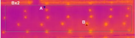
Further consideration relates to the selected area of 0,43×2,06 m, highlighted in Figure 3 as Bx2. This is a two-layer wall and its construc-tion is made in the System II. The minimum value of the temperature on the outer side of the layer wall, in this area (blue triangle, point A) is 4.7°C, the max value (red triangle, point B) is 7.2°C, while the average value is Tout = 5.1°C.
The ambient outdoor temperature during the measurement was Ta = 0.5°C, and the indoor am -bient temperature Tp = 23°C. The results obtained
by examination of thermal imaging provide
esti-mates of heat transfer coefficient [6], according to
the formula:
(8) where: αout - transfer coefficient and the heat
transfer partition at the interface with the
outside of the building, W/m2K.
This consideration assumes that the effects of solar radiation and the influence of such param -eters as humidity and pressure, which may change
the value of the coefficient of heat transfer, are ne
-glected. U-value is obtained by Equation (8) at the value of 0.198 [W/m2K]. This assumption can be made when total temperature differences are 5K
and solar radiator occurs mainly as a dispersed component. The obtained result is similar but does not coincide with the value U, determined for the
second analytical method. The difference is 0.015 [W/m2K] and it follows directly from the condi-tions in which the thermal imaging measurement was carried out, taking into account the occur-rence of thermal bridges in place of pegs.
CONCLUSIONS
The analysis of the thermal properties of three selected structural systems external wall, give
re-sults which indicate a significantly improved in -sulating properties of the wall built in the technol-ogy of permanent shuttering.
Thanks to the innovative technology based on materials of low thermal conductivity, c.a. 36.21% reduction in the U-values obtained for Izodom technology in relation to the ceramic blocks (Sys-tem II) and 19.13% in relation to the concrete
blocks (System III) was observed. One can find out that coefficient U = 0.148 [W/m2K], for Sys-tems II and III, would require to increase the insu-lation thickness of 76 cm and 40 cm, respectively in comparison to System I. The method uses
ther-mal imaging and allows to obtain sufficiently pre
-cise results of the heat transfer coefficient, which also confirms the usefulness of the test equipment
in the conducted analysis.
REFERENCES
1. Feist W., Basics of passive constructions, Polish Pas-sive House Institute, Gdańsk, 2006 (in Polish). 2. Information folder Izodom 2000 Polska, No. 11,
Jan-uary 2014 (in Polish).
3. Królczyk B., Energy-efficient and passive con
-struction: problem identification, Kunke Poligrafia, Poznań, 2013 (in Polish).
4. Lewandowski W., Environmentally friendly renew-able energy sources, Publisher WNT, Warszawa 2012 (in Polish).
5. Ślusarek J., Wilk-Słomka B., Thermal processes in build
-ing envelopes of a complex structure, Publisher Silesian University of Technology, Gliwice, 2010 (in Polish). 6. Technical folder SPB Part 1 – Hygrothermal
de-sign of cellular concrete walls – full structures, February 2013 (in Polish).
7. Urzędowski A., Izodom – a breakthrough in wall isola
-tion, Inżynier budownictwa, Oct. 2016, 83 (in Polish).
8. Urzędowski A., Wójcicka-Migasiuk D., Visual anal
-ysis of heat transport in unique object, Advances in Science and Technology Research Journal, 2015, 9(28), 153-159.
9. Wall solutions catalogue Porotherm, WBC, 2014 (in Polish).
10. Wójcicka-Migasiuk D., The analysis of heat ex
-change through solar walls, Lubelskie Towarzystwo Naukowe, Lublin 2008 (in Polish).
11. Wójcicka-Migasiuk D., Urzędowski A., Analysis of
demand, loss and profits of energy in passive building with thermal imaging technology, Herald of Khmel-nytskyi National University. Technical Sciences – 2016, No. 3, 214-217.
Fig. 3. Distribution of temperature on the wall