Copyright © 2013 IJECCE, All right reserved
A Dynamic Filter Architecture for Low Power
Consumption
Priya Stalin, Suja. K, Sanjuktha. J, Sasirekha. G, Suganya. M
Abstract - The paper presents an architectural approach to the design of low power reconfigurable finite impulse response (FIR) filter. The approach is well suited when the filter order is fixed and not changed for particular applications, and efficient trade-off between power savings and filter performance can be made using the proposed architecture. Generally, FIR filter has large amplitude variations in input data and coefficients. Considering the amplitude of both the filter coefficients and inputs, the proposed FIR filter dynamically changes the filter order. Mathematical analysis on power savings and filter performance degradation and its experimental results show that the proposed approach achieves significant power savings without seriously compromising the filter performance. The power savings is up to 20.5% with minor performance degradation, and the area overhead of the proposed scheme is less than 5.3% compared to the conventional approach.
Keywords – Approximate Filtering, Low Power Filter, Reconfigurable Design, High Speed Filter.
I. I
NTRODUCTIONThe demand for low power digital signal processing (DSP) systems has increased due to explosive growth in mobile computing and portable multimedia applications. One of the most widely used operations performed in DSP is finite impulse response (FIR) filtering. The input-output relationship of the linear time invariant (LTI) FIR filter can be expressed as the following equation:
where N represents the length of FIR filter, ck the kth coefficient, and x(n– k) the input data at time instant (n -k) . In many applications, in order to achieve high spectral
containment and/or noise attenuation, FIR filters with fairly large number of taps are necessary. Many previous efforts for reducing power consumption of FIR filter generally focus on the optimization of the filter coefficients while maintaining a fixed filter order [1]–[3]. In those approaches, FIR filter structures are simplified to add and shift operations, and minimizing the number of additions/subtractions is one of the main goals of the research. However, one of the drawbacks encountered in those approaches is that once the filter architecture is decided, the coefficients cannot be changed; therefore, those techniques are not applicable to the FIR filter with programmable coefficients. Approximate signal processing techniques [4] are also used for the design of low power digital filters [5], [6]. In [5], filter order dynamically varies according to the stopband energy of the input signal. However, the approach suffers from slow filter-order adaptation time due to energy computations in
the feedback mechanism. Previous studies in [6] show that sorting both the data samples and filter coefficients before the convolution operation has a desirable energy-quality characteristic of FIR filter. However, the overhead associated with the real-time sorting of incoming samples is too large. Reconfigurable FIR filter architectures are previously proposed for low power implementations [7]– [9] or to realize various frequency responses using a single filter [10]. For low power architectures, variable input length and filter taps [7], different coefficient word-lengths [8], and dynamic reduced signal representation [9] techniques are used. In those works, large overhead is incurred to support reconfigurable schemes such as arbitrary nonzero digit assignment [7] or programmable shift [8]. In this paper, we propose a simple yet efficient low power reconfigurable FIR filter architecture, where the filter order can be dynamically changed depending on the amplitude of both the filter coefficients and the inputs. In other words, when the data sample multiplied to the coefficient is so small as to mitigate the effect of partial sum in FIR filter, the multiplication operation can be simply canceled. The filter performance degradation can be minimized by controlling the error bound as small as the quantization error or signal to noise power ratio (SNR) of given system. The primary goal of this work is to reduce the dynamic power of the FIR filter, and the main contributions are summarized as follows. 1) A new reconfigurable FIR filter architecture with real-time input and coefficient monitoring circuits is presented. Since the basic filter structure is not changed, it is applicable to the FIR filter with programmable coefficients or adaptive filters. 2) We provide mathematical analysis of the power saving and filter performance degradation on the proposed approach. The analysis is verified using experimental results, and it can be used as a guideline to design low power reconfigurable filters. The rest of the paper is organized as follows. In Section II, the basic idea of the proposed reconfigurable filter is described. Section III presents the reconfigurable hardware architecture and circuit techniques used to implement the filter.
Discussions on the design considerations and
mathematical analysis of the proposed reconfigurable FIR filter are presented in Section IV. Section V shows the numerical results, followed by conclusions in Section VI.
a
Copyright © 2013 IJECCE, All right reserved
International Journal of Electronics Communication and Computer Engineering Volume 4, Issue 2, ISSN (Online): 2249–071X, ISSN (Print): 2278–4209
Fig.2. Amplitude of the 25-tap equi-ripple filter coefficients.
II. R
ECONFIGURABLEFIR F
ILTERING TOT
RADE OFFF
ILTERP
ERFORMANCE ANDC
OMPUTATIONE
NERGYAs shown in Fig. 1, FIR filtering operation performs the weighted summations of input sequences, called as convolution sum, which are frequently used to implement the frequency selective—low-pass, high-pass, or band-pass—filters. Generally, since the amount of computation and the corresponding power consumption of FIR filter are directly proportional to the filter order, if we can dynamically change the filter order by turning off some of booth's multipliers, significant power savings can be achieved. However, performance degradation should be carefully considered when we change the filter order. Fig. 2 exemplary shows the coefficients of a typical 25-tap low-pass FIR filter. The central coefficient has the largest value—the coefficient c12 has the largest value in the 25-tap FIR filter—and the amplitude of the coefficients generally decreases as becomes more distant from the center tap. The data inputs of the filter, which are multiplied with the coefficients, also have large variations in amplitude. Therefore, the basic idea is that if the amplitudes of both the data input and filter coefficient are small, the multiplication of those two numbers is proportionately small; thus, turning off the booth's multiplier has negligible effect on the filter performance. For example, since two’s complement data format is widely used in the DSP applications, if one or both of the booth's multiplier input has negative value, multiplication of two small values gives rise to large switching activities, which is due to the series of 1’s in the MSB part. By canceling the multiplication of two small numbers, considerable power savings can be achieved with negligible filter performance degradation. In the fixed point arithmetic of FIR filter, full operand bitwidths of the booth's multiplier outputs is not generally used. In other words, as shown in Fig. 1, when the bit-widths of data inputs and coefficients are 16, the booth's multiplier generates 32-bit outputs. However, considering the circuit area of the following adders, the LSBs of booth's multipliers outputs are usually truncated or rounded off, (e.g., 24 bits are used in Fig. 1) which incurs quantization errors. When we turn off the booth's multiplier in the FIR filter, if we can carefully select the input and coefficient
amplitudes such that the multiplication of those two numbers is as small as the quantization error, filter performance degradation can be made negligible. In the following, we denote threshold of input and threshold of coefficient as xth and cth, respectively. By threshold, we mean that when the filter input x(n) and coefficient ck are smaller than xth and cth , respectively, the multiplication is canceled in the filtering operation. When we determine xth and cth , the trade-off between filter performance and power savings should be carefully considered.
III. R
ECONFIGURABLEFIR F
ILTERA
RCHITECTUREIn this section, we present a direct form (DF) architecture of the reconfigurable FIR filter, which is shown in Fig. 3(a). The speed of the filter can be increased significantly, by replacing the conventional multiplier by a booth's multiplier. In order to monitor the amplitudes of input samples and cancel the right multiplication operations, amplitude detector (AD) in Fig. 3(b) is used. When the absolute value of x(n) is smaller than xth the threshold , the output of AD is set to “1”. The design of AD is dependent on the input threshold xth, where the fanin’s of AND and OR gate are decided by xth. If and
have to be changed adaptively due to designer’s considerations, AD can be implemented using a simple comparator.
Dynamic power consumption of CMOS logic gates is a strong function of the switching activities on the internal node capacitances. In the proposed reconfigurable filter, if we turn off the booth's multiplier by considering each of the input amplitude only, then, if the amplitude of input
x(n) abruptly changes for every cycle, the booth's
multiplier will be turned on and off continuously, which incurs considerable switching activities. Booth's multiplier control signal decision window (MCSD) in Fig. 3(a) is used to solve the switching problem. Using ctrl signal generator inside MCSD, the number of input samples consecutively smaller than xth are counted and the booth's multipliers are turned off only when m consecutive input samples are smaller than xth. Here, m means the size of MCSD [in Fig. 3(a), is equal to 4].
Copyright © 2013 IJECCE, All right reserved Fig.3. (b) Amplitude detection logic (AD)
Fig. 4(a) shows the ctrl signal generator design. As an input smaller than xth comes in and AD output is set to “1”, the counter is counting up. When the counter reaches
m, the ctrl signal in the figure changes to “1”, which indicates that m consecutive small inputs are monitored and the booth's multipliers are ready to turn off. One additional bit inct_n, in Fig. 3(a), is added and it is controlled by ctrl. The inct_n accompanies with input data all the way in the following flip-flops to indicate that the input sample is smaller than xth and the multiplication can be canceled when the coefficient of the corresponding booth's multiplier is also smaller than cth. Once the inct_n signal is set inside MCSD, the signal does not change outside MCSD and holds the amplitude information of the input. A delay component is added in front of the first tap for the synchronization between x*(n) and inctn in Fig. 3(a) since one clock latency is needed due to the counter in MCSD. In case of adaptive filters, additional ADs for monitoring the coefficient amplitudes are required as shown in Fig. 3(a). However, in the FIR filter with fixed or programmable coefficients, since we know the amplitude of coefficients ahead, extra AD modules for coefficient monitoring are not needed. extra AD modules for coefficient monitoring are not needed. When the amplitudes of input and coefficient are smaller than and, respectively, the booth's multiplier is turned off by setting
signal [Fig. 3(a)] to “1”. Based on the simple circuit technique [11] in Fig. 4(b), the booth's multiplier can be easily turned off and the output is forced to “0”. As shown
in the figure, when the control signal is “1”, since PMOS turns off and NMOS turns on, the gate output is
forced to “0” regardless of input. When is “0”, the gate operates like standard gate. Only the first gate of the booth's multiplier is modified and once the is set to “1”, there is no switching activity in the following nodes and booth's multiplieroutput is set to “0”. The area overheads of the proposed reconfigurable filter are flip-flops for
inct_n signals, AD and ctrl signal generator inside MCSD
and the modified gates in Fig. 4(b) for turning off booth's multipliers. Those overheads can be implemented using simple logic gates, and a single AD is needed for input
x(n) monitoring as specified in Fig. 3(a). Consequently,
the overall circuit overhead for implementing reconfigurable filter is as small as a single booth's multiplier.
Fig.4. (a) Schematic of ctrl signal generator. Internal counter sets ctrl signal to “1” when all input samples
inside MCSD are smaller than xth (m = 4 case). (b) Modified gate schematic to turn off booth's multiplier.
IV. D
ESIGNC
ONSIDERATIONS ANDM
ATHEMATICALA
NALYSIS ON THER
ECONFIGURABLEFIR F
ILTERIn this section, we present design considerations on the proposed reconfigurable FIR filter. Mathematical analysis which describes the trade-off between power savings and filter performance degradation is also presented.
A. Design Considerations
a
Copyright © 2013 IJECCE, All right reserved
International Journal of Electronics Communication and Computer Engineering Volume 4, Issue 2, ISSN (Online): 2249–071X, ISSN (Print): 2278–4209
factors that have a large effect on the proposed filter performance and power consumption are xth and cth . When xth and cth are set too large, it can give rise to large power savings with considerable distortion in the filter output. On the other hand, if xth and cth are too small, power savings become trivial.
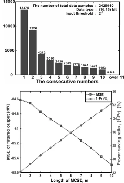
The other one to be considered is m , the length of MCSD. Fig. 5 shows the number of input samples whose
m(x axis) consecutive input values are smaller than input
threshold. The input signals used in the simulation are more than ten samples of sounds and speeches. In Fig. 5, if we choose a specific value in the axis, the total number of canceled multiplications is the accumulated number of samples from the selected value to the right. Therefore, if
m becomes larger, the number of input samples that make
booth's multipliers turned off decreases; then, power reduction becomes smaller and filter performance degradation becomes lower as well. Fig. 6 shows the trade-off between the power saving ratio (1 - Pr) and the MSE for different m values in case of a 75-tap equi-ripple filter with xth and cth of 2–7.
B. Mathematical Analysis
Mathematical modelings on the power savings and performance degradation of the proposed reconfigurable FIR filter are presented in this subsection. Detailed derivations can be found in the Appendix. Assuming the input signal as stationary random Markov process as commonly used in communication systems [12], where the future state is independent of its past states and conditionally dependent only on the present state, power saving ratio, (1 - Pr) , can be expressed as,
1 2 Pr Pr
1Pr c xPcutmcut Where Prc (= Pr{ | ck |≤ cth } ) and
Prx ( = Pr { | x (n - k ) |≤ xth} )
are the probability that the amplitude of the coefficient and input signal are less than the given thresholds, i.e., ck ≤ cth ,and | x (n–k ) ≤ xth|, respectively. Pcut2cut is the conditional probability meaning that future state of input samples is smaller than xth under present state being also smaller than xth ,
note that power savings of the proposed reconfigurable filter are directly affected by the probabilities of inputs and coefficients being smaller than xth and cth , respectively, as well as the conditional probability. Pcut2cut which is dependent upon time correlation characteristics of the input signal. It is also a function of the MCSD window size m. As a metric of filter performance degradation, the
MSE of the filter output is described as,
1
0 1
0 2 2 2
, Pr
N
tc C h h
th cut x
k h N
tc C k k x c
e c c r h k prob x h k m
Where (= E{x2(n)}) is the average input signal power, rx( h - k ) is time correlation of input signal spaced
by ( h - k ), and kϵCtc denotes a set of k where the kth
filter coefficient is smaller than cth ,i.e, |ck|≤ cth. .
Here, probcut (xth, | h - k | , m) is the probability that the
input samples at (n-h), (n-h-1),…,(n-h-m+1) and k),
(n-k-1),…,(n-k-m+1) are smaller than xth, which is
represented as ,
Above equation shows that the MSE is mainly determined by the filter coefficient, input signal power, auto-correlation of the input signal, and probability of input samples being smaller than xth.
V. N
UMERICALR
ESULTSIn this section, we have designed and implemented various types of reconfigurable FIR filters. Mathematical analysis in the previous section are verified by comparing with the experimental results.
A. Reconfigurable FIR Filter Specifications
Following are the specifications on the FIR filters implemented.
• Input sequence and coefficients are 16-bit data with fractional part of 15 bit. Hence, the data range is [-1,1] • The outputs of the booth's multiplier in the FIR filter
are quantized into 16 bit and the final filter output is 24 bit.
• We use 2-7 as an input threshold, xth, and coefficient
threshold, cth. The values of MCSD window length, m,
are differently assigned for the filters. The values of
xth, cth and can be controlled by users considering the
performance degradation and power savings trade-off presented in Section IV-B.
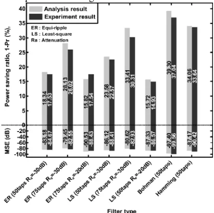
B. Numerical Results
Copyright © 2013 IJECCE, All right reserved (MSE) was also compared with the experimental results
for various reconfigurable filters as seen in Fig. 7. We can notice from the figure that the differences between the mathematical modeling and experimental results are very small. To analyze the filter performance degradation, we define signal power to MSE ratio of the filter output (SMR) considering the effective ratio of the desired signal and the distorted error signal power as
1 0 1 0 2 1 0 1 0 2 2 , Pr N tc C h h th cut x k h N tc C k k c N k N k h k e y m k h x prob k h r c c k h r c c SMR Table II also presents the SMR results of various filters. For most of the cases, the SMR is larger than 45 dB, meaning that MSE is almost ignorable. For given applications, if SMR is comparable or larger than the signal to quantization error power ratio or the SNR of a given system, which are usually less than 30 dB [12], the performance degradation of proposed reconfigurable FIR filter can be considered negligible. The area overhead to support the proposed reconfigurable scheme is around 5.3% in case of 25-tap filter and it is even smaller for 50 and 75-tap filters, which are shown in Table II Fig. 8 also illustrates the filter order changes due to canceling multiplications according to the input samples’ amplitudes.. Power saving ratio of each filter is normalized with the number of taps, the precision of input samples and coefficients, process technology, supply voltage, and clock frequency using the following equation [7]: Table I Filter parameters Delay Power consumption % increase in area % increase in speed Power saving % Existing system 4.210ns 334mW
5.3% 4.67% 15% Proposed
system
4.015ns 285mW
Our proposed filter shows larger power savings than the filters in [7] and [9]. The reconfigurable filter in [5] consumes less power than our proposed filter; however, MSE is even larger. Under the similar 1 - Pr obtained by
adjusting parameter values, our proposed filter has much less MSE. Phonetic signal processing system is a good application to use the proposed reconfigurable filtering approach. Voice signal is usually composed of
Table II: Average power saving ratio (1-pr) (%), the average MSE and SMR for various filter types in speech
signal case
Copyright © 2013 IJECCE, All right reserved (MSE) was also compared with the experimental results
for various reconfigurable filters as seen in Fig. 7. We can notice from the figure that the differences between the mathematical modeling and experimental results are very small. To analyze the filter performance degradation, we define signal power to MSE ratio of the filter output (SMR) considering the effective ratio of the desired signal and the distorted error signal power as
1 0 1 0 2 1 0 1 0 2 2 , Pr N tc C h h th cut x k h N tc C k k c N k N k h k e y m k h x prob k h r c c k h r c c SMR Table II also presents the SMR results of various filters. For most of the cases, the SMR is larger than 45 dB, meaning that MSE is almost ignorable. For given applications, if SMR is comparable or larger than the signal to quantization error power ratio or the SNR of a given system, which are usually less than 30 dB [12], the performance degradation of proposed reconfigurable FIR filter can be considered negligible. The area overhead to support the proposed reconfigurable scheme is around 5.3% in case of 25-tap filter and it is even smaller for 50 and 75-tap filters, which are shown in Table II Fig. 8 also illustrates the filter order changes due to canceling multiplications according to the input samples’ amplitudes.. Power saving ratio of each filter is normalized with the number of taps, the precision of input samples and coefficients, process technology, supply voltage, and clock frequency using the following equation [7]: Table I Filter parameters Delay Power consumption % increase in area % increase in speed Power saving % Existing system 4.210ns 334mW
5.3% 4.67% 15% Proposed
system
4.015ns 285mW
Our proposed filter shows larger power savings than the filters in [7] and [9]. The reconfigurable filter in [5] consumes less power than our proposed filter; however, MSE is even larger. Under the similar 1 - Pr obtained by
adjusting parameter values, our proposed filter has much less MSE. Phonetic signal processing system is a good application to use the proposed reconfigurable filtering approach. Voice signal is usually composed of
Table II: Average power saving ratio (1-pr) (%), the average MSE and SMR for various filter types in speech
a
Copyright © 2013 IJECCE, All right reserved
International Journal of Electronics Communication and Computer Engineering Volume 4, Issue 2, ISSN (Online): 2249–071X, ISSN (Print): 2278–4209
n attenuatio stopband
: , frequency off
cut :
n, attenuatio stopband
: , passband narmalized
:
a c
s p
R
considerable portions of data samples with small amplitude. Though we focused on the FIR filters with fixed coefficients in this work, our proposed approach can be extended to the adaptive filter cases, where both data inputs and coefficients amplitude should be monitored simultaneously.
VI. C
ONCLUSIONA low power reconfigurable FIR filter architecture allows efficient trade-off between the filter performance (in terms of area increase) and computation energy. In the proposed architecture, the input data are monitored and the multipliers in the filter are turned off when both the coefficients and inputs are small enough to mitigate the effect on the filter output. Numerical results show that the proposed scheme achieves considerable power savings with less than around 5.34% of area overhead with very graceful degradation in the filter output. The proposed approach can be applicable to other areas of signal processing, where a proper trade-off between power savings and performance degradation should be carefully considered. Filters have 2 uses: Signal Seperation and restoration. The idea presented in this paper can assist in the design of FIR filters and its implementation for low power applications.
A
PPENDIXIn the Appendix, we show the detail derivations of power savings and MSE of the proposed reconfigurable FIR filter.
Power Saving Analysis:
Since turning-off multiplier in each tap can be regarded as Bernoulli random variable , turning off inside the proposed filter is binomial random variable. As a result, the power saving ratio is equal to the probability that turning-off happens. Assume that input signal as stationary Markov process,,the power saving ratio can be represented as,where probcut(xth,m) is the probability that the input signal
is turned off, which can be represented by,
Where, Prc( = Pr{ | ck| ≤ cth} ) and
Prx ( = Pr{ | x ( n–k ) | ≤ xth} ) are the probabilities
that the amplitude of the coefficient and input signal are less than the given thresholds,i.e, |ck|≤cthand | x ( n–k)|≤
xth , respectively. Pcut2cutis the conditional probability that
input turn-off condition,. i.e., input is lessthan xth, happens
given that the turn-off condition occurs for the input signal represented as,
Note that Pcut2cut depends upon the characteristics of the
input signal which is specific to its own applications. While the above analysis is driven for more general “partially- correlated” cases using Markov process approximation, two extreme cases can be considered for more intuitive understanding.
• Case 1: timely independent signal
• Case 2: fully correlated independent signal
Therefore, probcut(xth,m) has the following inequality,
Thus, (1 – Pr) (independent) ≤ (1- Pr) (partially
correlated)≤(1 - Pr) (fully correlated), implying that the
power saving ratio also depends upon the input signal’s time correlation characteristics.
Performance Degradation (MSE) Analysis:
Here, k ϵ ϒtc denotes a case where booth's multiplier
turn-off occurs at k, i.e. ck|≤ cth, |x ( n–k ) |≤ xth,…, x
(n-k-m+1)≤xth. Then, the erroring of filter output is at, i.e.,
The MSE of the filter output can be represented by,
2
2 Een |
e
Copyright © 2013 IJECCE, All right reserved Approximating xn-hxn-k= 2xrx(h-k) for a simpler closed
form analysis, the MSE can be written by (13) at the bottom of the page, where represents a case when the kth coefficient is smaller than cth, i.e., |ck|≤ cth. Here, probcut (xth, h-k, m) is the probability that input samples are turned
off both at time (n-h) and (n-k), i.e., p {x (n-h)≤xth,…, x( n-h-m+1 ) ≤ xth,…, x(n-k-m+1) ≤ xth}, which can be
simplified as ,
xn hxn k
r
h k
E
x2 x is the time correlation ofthe input signals.
R
EFERENCES[1] H. Samueli, “An improved search algorithm for the design of
booth's multiplierless FIR filter with powers-of-two
coefficients,” IEEE Trans. Circuits Syst., vol. 36, no. 7, pp.
1044–1047, Jul. 1989.
[2] R. I. Hartley, “Subexpression sharing in filters using canonical
signed digit booth's multipliers,”IEEE Trans. Circuits Syst. II, Analog Digit. Signal Process., vol. 43, no. 10, pp. 677–688, Oct. 1996.
[3] O. Gustafsson, “A difference based adder graph heuristic for multiple constant multiplication problems,” inProc. IEEE Int. Symp. Circuits Syst., 2007, pp. 1097–1100.
[4] S. H. Nawab, A. V. Oppenheim, A. P. Chandrakasan, J. M. Winograd,and J. T. Ludwig, “Approximate signal processing,”
J. VLSI Signal Process., vol. 15, no. 1–2, pp. 177–200, Jan. 1997.
[5] J. Ludwig, H. Nawab, and A. P. Chandrakasan, “Low power
digitalfiltering using approximate processing,” IEEE J. Solid-State Circuits, vol. 31, no. 3, pp. 395–400, Mar. 1996.
[6] A. Sinha, A. Wang, and A. P. Chandrakasan, “Energy scalable
systemdesign,”IEEE Trans. Very Large Scale Integr. Syst., vol.
10, no. 2, pp. 135–145, Apr. 2002.
[7] K.-H. Chen and T.-D. Chiueh, “A low-power digit-based reconfigurable FIR filter,”IEEE Trans. Circuits Syst. II, Exp. Briefs, vol. 53, no. 8, pp. 617–621, Dec. 2006.
[8] R. Mahesh and A. P. Vinod, “New reconfigurable architectures
for implementing filters with low complexity,” IEEE Trans. Comput.-Aided Des. Integr. Circuits Syst., vol. 29, no. 2, pp.
275–288, Feb. 2010.
[9] Z. Yu, M.-L. Yu, K. Azadet, and A. N. Wilson, Jr, “A low power
FIR filter design technique using dynamic reduced signal
representation,” in Proc. Int. Symp. VLSI Tech., Syst., Appl., 2001, pp. 113–116.
[10] R. Mahesh and A. P. Vinod, “Coefficient decimation approach
for realizingreconfigurable finite impulse response filters,” in
Proc. IEEE Int.Symp. Circuits Syst., 2008, pp. 81–84.
[11] J. Park and K. Roy, “A low complexity reconfigurable DCT
architecture to trade off image quality for power consumption,”
J. Signal Process. Syst., vol. 53, no. 3, pp. 399–410, Dec. 2008. [12] J. G. Proakis, Digital Communications, 3rd ed. New York:
McGraw- Hill, 1995.
[13] Synopsys, Inc., Nanosim Reference Guide, 2007.
A
UTHOR'
SP
ROFILEPriya Stalin
The author Priya Stalin is working as an Asst. Professor in Sree Sastha Institute of Engineering and Technology. She has completed her Bachelors' degree in Karunya Institute of Technology, ( Barathiar University, Coimbatore) and her post graduation in Applied Electronics in Velammal Engineering College,(Anna university, Chennai). She is currently pursuing her Ph.D in VLSI at St.Peters' University, Avadi Chennai. She has 13years of teaching experience, and her fields of interest are VLSI, Digital Signal Processing and Computer Networks.
Suja. K
The author Ms.K.Suja is working as an Asst. Professor in Sree Sastha Institute of Engineering and Technology. She has completed her graduation at Jerusalem college of Engineering and her post graduation in Sathyamabama Deemed University. She holds a teaching experience of 14 years in different fields such as VLSI design, Digital Electronics, LIC and Microprocessors.
E-mail ID:sujaganesan@gmail.com
Sanjuktha. J
The author Ms. J.Sanjuktha is pursuing her
bachelor’s degree in Electronics and Communication
Engineering, at Sree Sastha Institute of Engineering and Technology. Her fields of interests are VLSI Design and Digital Electronics. Her research interest includes low power circuit and system design for digital signal processing systems.
E-mail ID: sanjukthajanakan@yahoo.co.on
Sasirekha. G
The author Ms. Sasirekha.G is pursuing her
bachelor’s degree in Electronics and Communication
Engineering, at Sree Sastha Institute of Engineering and Technology. Her fields of interest are Digital Signal Processing, Wireless Communication and VLSI design. Her research includes low-power, and high-performance VLSI architectures and circuit designs for digital signal processing and digital communications. E-mail ID: sasi.2092@gmail.com
Suganya. M
The author Ms. Suganya. M is pursuing her
bachelor’s degree in Electronics and Communication
Engineering, at Sree Sastha Institute of Engineering and Technology. Her fields of interest are Digital Electronics and Digital Signal Processing. Her fields of research are Circuits, Signals and System Processing and Digital Analytics.