Slip Ratio Control of Anti-Lock Braking System with Bang-Bang
Controller
Dankan Gowda V*, Ramachandra A C**
*(Electronics & Communication Engineering, Sri Venkateshwara College of Engineering, and Bengaluru) ** (Electronics & Communication Engineering, Alpha College of Engineering, and Bengaluru)
---
************************
---Abstract:
Anti-lock Braking system (ABS) is a safety and control tool implemented in vehicles that prevents the wheel lock-up during severe or panic braking. The existing ABS controls have the ability to control and regulate the level of pressure to optimally maintain the wheel slip within the vehicle stability range. However, the ABS shows strong nonlinear characteristics for which the vehicle equipped with existing controllers have a tendency to over steer and become unstable. In this paper a mathematical model of ABS with Bang-Bang control algorithm have been implemented in Simulink and extensive simulation studies is also performed to verify the effectiveness of the controller and the results shows that proposed controller is able to maintain the wheel slip at the desired reference value. The braking performance in both ABS mode and Non-ABS mode has been evaluated by simulation.
.
Keywords —Anti Lock Breaking System, Bang-Bang Controller, Simulink, Wheel Slip.
---
************************
---I. INTRODUCTION
Antilock breaking system (ABS) is used in advanced automobiles to prevent slip and locking of wheel after brakes applied. it is automobile safety system, the controller is provided to control the necessary torque to maintain optimum slip ration. The slip ratio denotes in terms of vehicle speed and wheel rotation. The world’s first abs controller for passenger cars was introduced in 1978 by Bosch, with the primary objectives of preventing wheel-lock, reducing stopping distance and enhancing steerability during braking [1]. There are conceptually two types of control strategies being used in abs controllers: (a) acceleration-control based, and (b) slip-control based. the former indirectly controls the slip by using wheel deceleration/acceleration which is computed from the wheel angular velocity measurements. The major disadvantage of this method of control is the noticeable vibrations experienced during braking. Theoretically, the slip-control based method is the ideal method. it involves keeping the actual slip rate at an optimal target slip using continuous control
during braking [2]. ABS modulates the brake line pressure independent of the pedal force, to bring the wheel speed back to the slip level range that is necessary for optimal braking performance. An anti-lock system consists of wheel speed sensors, a hydraulic modulator, and electronic control unit. The abs has a feedback control system that modulates the brake pressure in response to wheel deceleration and wheel angular velocity to prevent the controlled wheel from locking. The system shuts down when the vehicle speed is below a pre-set threshold. This paper focuses on mathematical modelling of an abs using a bang-bang controller has been implemented in simulink. The braking performances in both abs mode and non-abs mode have been evaluated by simulation.
A. Objectives of ABS: (1) to reduce stopping distances, (2) to improve stability, and (3) to improve steerability during braking.
1) Stopping distance: the distance to stop is a function of the mass of the vehicle, the initial velocity, and the braking force. By maximizing the braking force the stopping distance will be minimized if all other
International Journal of Computer Techniques – Volume 4 Issue 1, Jan – Feb 2017
ISSN :2394-2231 http://www.ijctjournal.org Page 98
factors remain constant. However, on all types of surfaces, to a greater or lesser extent, there exists a peak in friction coefficient. It follows that by keeping all of the wheels of a vehicle near the peak, an antilock system can attain maximum frictional force and, therefore, minimizes stopping distance. This objective of antilock systems however, is tempered by the need for vehicle stability and steerability.
2) Stability: Although decelerating and stopping vehicles constitutes a fundamental purpose of braking systems, maximum friction force may not be desirable in all cases, for example not if the vehicle is on a so-called p-split surface (asphalt and ice, for example), such that significantly more braking force is obtained on one side of the vehicle than on the other side. Applying maximum braking force on both sides will result in a yaw moment that will tend to pull the vehicle to the high friction side and contribute to vehicle instability, and forces the operator to make excessive steering corrections to counteract the yaw moment. If an antilock braking system can maintain the slip of both rear wheels at the level where the lower of the two friction coefficients peaks, then lateral force is reasonably high, though not maximized. This contributes to stability and is an objective of antilock braking systems.
3) Steerability: Good peak frictional force control is necessary in order to achieve satisfactory lateral forces and, therefore, satisfactory steerability. Steerability while braking is important not only for minor course corrections but also for the possible of steering around an obstacle. Tire characteristics play an important role in the braking and steering response of a vehicle. For ABS-equipped vehicle the tire performance is of critical significance. All braking and steering forces must be generated within the small tire contact patch between the vehicle and the road. Tire traction forces as well as side forces can only be produced when a difference exists between the speed of the tire circumference and the speed of the vehicle relative to the road surface .this difference is denoted as slip. It is common to relate the tire braking force to the tire braking slip. After the peak value has been reached,
increased tire slip causes reduction of tire-road friction coefficient. ABS has to limit the slip to values below the peak value to prevent wheel from locking. Tires with a high peak friction point achieve maximum friction at 10 to 20% slip. The optimum slip value decreases as tire-road friction decreases.
B. The ABS Sub-systems:
1) Wheel-Speed Sensors: Electro-magnetic or Hall-effect pulse pickups with toothed wheels mounted directly on the rotating components of the drive train or wheel hubs. As the wheel turns the toothed wheel (pulse ring) generates an AC voltage at the wheel-speed sensor. The voltage frequency is directly proportional to the wheel's rotational speed. 2) Electronic Control Unit (ECU):The electronic control unit receives, amplifies and filters the sensor signals for calculating the wheel rotational speed and acceleration. This unit also uses the speeds of two diagonally opposed wheels to calculate an estimate for the speed of the vehicle. The slip at each wheel is derived by comparing this reference speed with the speeds of the individual wheels. The "wheel acceleration" and "wheel slip" signals serve to alert the ECU to any locking tendency. The microcomputers respond to such an alert by sending a signal to trigger the pressure control valve solenoids of the pressure modulator to modulate the brake pressure in the individual wheel-brake cylinders. The ECU also incorporates a number of features for error recognition for the entire ABS system (wheel-speed sensors, the ECU itself, pressure-control valves, wiring harness). The ECU reacts to a recognized defect or error by switching off the malfunctioning part of the system or shutting down the entire ABS.
motor assembly, accumulator and reservoir. Fig 1 shows relationship between modulator, dynamics and controller.
Fig.1: Block diagram of Antilock Braking System
II.LITERATURE REVIEW
Mirzaeinejad and Mirzaei [3] have applied a predictive approach to design a non- linear model based controller for the wheel slip. The integral feedback technique is also employed to increase the robustness of the designed controller. Therefore, the control law is developed by minimizing the difference between the predicted and desire responses of the wheel slip and it’s integral.
Baslamisliet al. [4] proposed a static-state feedback control algorithm for ABS control. The robustness of the controller against model uncertainties such as tire longitudinal force and road adhesion coeffic has been guaranteed through the satisfaction of a set of linear matrix inequalities. Robustness of the controller against actuator time delays along with a method for tuning controller gains has been addressed. Further tuning strategies have been given through a general robustness analysis, where especially the design conflict imposed by noise rejection and actuator time delay has been addressed.
Choi [5] has developed a new continuous wheel slip ABS algorithm. here ABS algorithm, rule control of wheel velocity is reduced to the minimum. Rear wheels cycles independently through pressure apply, hold, and dump modes, but the cycling is done by continuous feedback control. While cycling rear wheel speeds, the wheel peak slips that maximize tire-to-road friction are estimated. From the estimated peak slips, reference velocities of front wheels are calculated. The front wheels are controlled continuously to track the r assembly, accumulator and reservoir. Fig 1 shows relationship between modulator, dynamics
Fig.1: Block diagram of Antilock Braking System
Mirzaeinejad and Mirzaei [3] have applied a linear model-based controller for the wheel slip. The integral feedback technique is also employed to increase the robustness of the designed controller. Therefore, the control law is developed by minimizing the difference between the predicted and desired responses of the wheel slip and it’s integral.
state feedback control algorithm for ABS control. The robustness of the controller against model uncertainties such as tire longitudinal force and road adhesion coefficient has been guaranteed through the satisfaction of a set of linear matrix inequalities. Robustness of the controller against actuator time delays along with a method for tuning controller gains has been addressed. Further tuning strategies have been n through a general robustness analysis, where especially the design conflict imposed by noise rejection and actuator time delay has been
Choi [5] has developed a new continuous wheel slip ABS algorithm. here ABS algorithm, rule-based wheel velocity is reduced to the minimum. Rear wheels cycles independently through pressure apply, hold, and dump modes, but the cycling is done by continuous feedback control. While cycling rear wheel speeds, the wheel peak ad friction are estimated. From the estimated peak slips, reference velocities of front wheels are calculated. The front wheels are controlled continuously to track the
reference velocities. By the continuous tracking control of front wheels without cyclin
performance is maximized.
Rangelov [6] described the model of a quarter vehicle and an ABS in MATLAB
this report, to model the tire characteristics and the dynamic behavior on a flat as well as an uneven road, the SWIFT-tire model is employed.
Sharkawy [7] studied the performance of ABS with variation of weight, friction coefficient of road, road inclination etc. A self-tuning PID control scheme to overcome these effects via fuzzy GA is developed; with a control objective to minimize stopping distance while keeping slip ratio of the tires within the desired range.
Poursmad [8] has proposed an adaptive NN
controller for ABS. The proposed controller is designed to tackle the drawbacks of feedback linearization controller for ABS.
Topalovet al. [9] proposed a neurofuzzy adaptive control approach for nonlinear system with model uncertainties, in antilock braking systems. The control scheme consists of PD controller and an inverse reference model of the response of controlled system. Its output is used as an error signal by an online algorithm to update the parameters of a neuro-fuzzy feedback controller. Patil and Longoria[10] have used decoupling feature in frictional disk brake mechanism derived through kinematic analysis of ABS t
reference braking torque is presented. Modeling of ABS actuator and control design are described. Layne et al. [11] have illustrated the fuzzy model reference learning control (FMRLC). Braking effectiveness when there are transition between icy and wet road surfaces is studied.
Huang and Shih [12] have used the fuzzy controller to control the hydraulic modulator and hence the brake pressure. The performance of controller and hydraulic modulator are assessed by the hardware in loop (HIL) experiments.
Onitet al. [13] have proposed a novel strategy for the design of sliding mode controller (SMC). As velocity of the vehicle changes, the optimum value of the wheel slip will also alter. Gray predictor is employed to anticipate the future output of the system.
reference velocities. By the continuous tracking control of front wheels without cycling, braking
Rangelov [6] described the model of a quarter-vehicle and an ABS in MATLAB-SIMULINK. In this report, to model the tire characteristics and the dynamic behavior on a flat as well as an uneven
s employed.
Sharkawy [7] studied the performance of ABS with variation of weight, friction coefficient of road, tuning PID control scheme to overcome these effects via fuzzy GA is developed; with a control objective to minimize stopping distance while keeping slip ratio of the
Poursmad [8] has proposed an adaptive NN- based controller for ABS. The proposed controller is designed to tackle the drawbacks of feedback linearization controller for ABS.
Topalovet al. [9] proposed a neurofuzzy adaptive control approach for nonlinear system with model uncertainties, in antilock braking systems. The control scheme consists of PD controller and an inverse reference model of the response of . Its output is used as an error signal by an online algorithm to update the
fuzzy feedback controller. Patil and Longoria[10] have used decoupling feature in frictional disk brake mechanism derived through kinematic analysis of ABS to specify reference braking torque is presented. Modeling of ABS actuator and control design are described. Layne et al. [11] have illustrated the fuzzy model reference learning control (FMRLC). Braking effectiveness when there are transition between icy
nd wet road surfaces is studied.
Huang and Shih [12] have used the fuzzy controller to control the hydraulic modulator and hence the brake pressure. The performance of controller and hydraulic modulator are assessed by the hardware
International Journal of Computer Techniques – Volume 4 Issue 1, Jan – Feb 2017
ISSN :2394-2231 http://www.ijctjournal.org Page 100
III. SCOPE&OBJECTIVEOFPRESENT WORK
During the design of ABS, nonlinear vehicle dynamics and unknown environment characters as well as parameters, change due to mechanical wear have to be considered. PI controller are very easy to understand and easy to implement. However PI loop require continuous monitoring and adjustments. In this line there is a scope to understand Bang-Bang controllers with mathematical models. The present work, it is planned to understand and obtain the dynamic solution of quarter car vehicle model to obtain the time varying vehicle velocity and wheel. After identification of system dynamics a slip factor defined at each instance of time will be modified to desired value by means of a control scheme. Various feedback control schemes can be used for this purpose. Simulation are carried out to achieve a desired slip factor with control scheme such as Bang-Bang controller Graphs of linear velocity, stopping distance and slip ratio for each system is plotted and compared with each other.
IV. MATHEMATICALMODELING
Mathematical modeling is the first and most crucial task in developing a control algorithm for the antilock braking system. However, modeling an antilock braking system is really a difficult tusk,considering the ABS dynamics being highly nonlinear and time varying .However, in this paper, a simplified model for controller design and computer simulation is used. Towards the above goal, the mathematical model of an ABS has been implemented in Simulink, which employs a quarter car vehicle model undergoing a straight line braking maneuver[14]. The model also incorporates a hydraulic brake actuator dynamics and road-tire friction. The road-tire friction model [15] is given in the form of an empirical function describing the nonlinear relation between adhesion coefficient and wheel slip. A Bang-Bang controller has been implemented with the above model for controlling wheel slip at given desired reference value. The braking performances in both in ABS mode & non-ABS mode have been evaluated by simulation.
A. Wheel Model
The tractive force between a tire and the road surface (Figure. 1) is proportional to the normal load , the constant of proportionality being termed the Friction coefficient . The Friction coefficient is the ratio of tire brake force at the tire road interface and the normal load acting on the tire.
= ……. (1)
Fig.2 wheel model [15]
The value of is highly dependent on tire characteristics (compound, wear, aging, etc.) and road surface conditions (dry, icy, gravel, tarmac, etc.), although it can be primarily regarded as a function of the relative slip between the two contacting surfaces. By definition, slip is the normalized difference between the wheel speed and vehicle speed at the contact point
= ………. (2)
where is the vehicle velocity, is the effective radius of the driven wheel, and is the angular velocity of the wheel. Typical − characteristics are shown in Figure2.
Fig.3 Example − Characteristics for various road conditions [16]
The objective of an ABS is to manipulate the torque applied to the driven wheels in order to limit the slip between the road surface and the tire, and consequently, only operate within the stable region of the − characteristic. A major obstacle in the practical design of ABS control schemes is the determination, in real time, of − characteristics, i.e., and. For example, Table I shows typical values of slip required to obtain the maximum friction coefficient for various road conditions.
TABLEI
MAXVALUES OF Μ FOR VARIOUS ROAD SURFACES [16]
Road Condition Maximum Friction
Co-efficient ( ) Optimum Slip( )
Dry Road 0.85 0.35
Wet Road 0.4 0.2
Icy Road 0.2 0.1
To overcome this problem, many manufacturers employ a slip-limiting control scheme to account for “worst case” conditions, typically icy roads. Although this constitutes the safest criteria to adopt for design purposes, it can impose conservative limits on the traction available under less severe conditions [17]. A second obstacle often encountered by designers of ABS schemes is the availability of appropriate test-tracks/skid-pans or other experimental rolling road facilities to evaluate proposed algorithms and provide repeatable conditions for comparative studies.
B. Vehicle Dynamics
A simplified quarter car vehicle model undergoing perfectly straight line braking maneuver has been considered. Thus there is no lateral tire force and also yaw do not exist.
Further the following assumptions are considered in the modeling process
1. There is no steering input.
2. Only longitudinal vehicle motion has been considered.
3. The sprung mass is assumed to be connected to unsprung mass with a rigid body (no damping effect)
4. Approximating the vehicle forces as a static value.
The equation of motion is given by: =− … … . . (3)
= − … … . . (4)
The tire friction force is given by the coulomb’s Law
= ( ) … … . (5)
The Longitudinal wheel slip is given by = ( − )/ ……..(6)
And the friction coefficient is given by the following function
( ) = 2 ( + )…..(7) Where, = Longitudinal Force.
= Braking torque = Vehicle velocity
= quarter vehicle mass =coefficient of friction
=Peak friction coefficient = wheel angular velocity =radius of the wheel.
=moment of inertia of the wheel.
C. Hydraulic Brake Dynamics
International Journal of Computer Techniques – Volume 4 Issue 1, Jan – Feb 2017
ISSN :2394-2231 http://www.ijctjournal.org Page 102
Fig. 4 Hydraulic Brake System
Here, to control the rate of change of brake pressure, the model subtracts actual slip from the desired slip and feeds this signal into a bang-bang control (+1 or -1, depending on the sign of the error.) this on/off rate passes through a first-order lag that represent the delay associated with the hydraulic lines of the brake system. The model then integrates the filtered rate to yield the actual brake pressure. The resulting signal, multiplied by the piston area and radius with respect to the wheel ( ), is the brake torque applied to the wheel.
D. Bang-Bang Control Law
An Anti-lock Braking System that uses ‘bang-bang’ control based upon the error between actual slip and desired slip. Set the desired slip to the value of slip at which the − curve reaches a peak value, this being the optimum value for minimum braking distance. The control input, namely the brake torque , is switched between the maximum value, , and the minimum value, 0, so as to keep the slip operating in the desired region. From the figure below taking
=0.2.
Fig.5 mue ( ) − ( ) [18]
V.SIMULATION
The Vehicle dynamic model is dealing with the movements of vehicles on a road surface. The movements of interest are acceleration, braking, ride, and turning. Dynamic behavior is determined by the forces imposed on the vehicle from the tires, gravity, and aerodynamics. A simplified longitudinal vehicle model considering vehicle/tire/road dynamics and hydraulic brake system dynamics is described in section 4.3. A list of variables and simulation parameters used in this model is given in Table II.
TABLE II
SIMULATION PARAMETERS USED FOR DEVELOPMENT OF BANG-BANG
CONTROLLER.
PARAMETER DESCRIPTION VALUE
M QUARTER CAR MASS 300KG
V INITIAL VEHICLE VELOCITY 70(M/SEC)
W INITIAL WHEEL VELOCITY 120(RAD/SE)
R WHEEL RADIUS 1.25M
G GRAVITATIONAL CONSTANT 9.81(M/S)
J MOMENT OF INERTIA OF WHEEL 1.6 KG M
FZ NORMAL FORCE 50N
T MAXIMUM BRAKING TORQUE 1200NM
Λ DESIRED SLIP 0.2
K GAIN 100
The goal of the Antilock brake system is to hold each tire of the vehicle operating near the peak of the − curve for that tire, which implies performance of an ABS is strongly related to the surface condition.
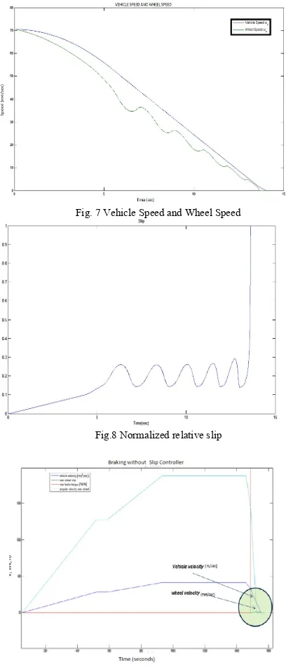
Fig. 7 Vehicle Speed and Wheel Speed
Fig.8 Normalized relative slip
Fig. 9 Braking without Bang-Bang Controller
From the Figure.9 it is seen that as the angular velocity of rear wheel increases, the vehicle velocity increases proportionately. When the rider applies sudden brake while riding, the wheel locks. In this situation, the angular velocity of the wheel drastically decreases to zero, but the vehicle velocity takes longer time due to moment of inertia. This causes the bike to skid, slip increases to one and the bike is in unstable situation.
Due to applying a sudden brake the wheel velocity comes down to zero drastically, but due to inertia still have some vehicle velocity.
Fig. 10 Braking with Bang-Bang Controller
As seen in the Figure10. when ABS is ON, the reference slip is set to 0.2. When the rider brakes drastically, the wheel locks’s and slip starts increasing. When the slip increases beyond 0.2 the ABS controller modulates the brake pressure and releases the brake. As the wheel speed is not in sync with the vehicle speed, the brakes are applied again. This cycle repeats till the slip is under the reference value. This results in matching of vehicle velocity and wheel velocity which in turn result in stability of the vehicle.
VI. CONCLUSION
In this paper a mathematical model of an ABS system was considered and a slip-ratio based on Bang-Bang controller was implemented. The performance of vehicle Braking with and without Bang-Bang controller was compared and analyzed. Braking with Bang-Bang Controller mode the wheel speed and the vehicle speed sets down at the same time and the slip distance, speed and relative slip of the vehicle is founded. In the simulation it is concluded that the Bang-Bang Controller has better braking performance because the wheel speed and the vehicle speed is been controlled at the same time in order to avoid the vehicle to skid during the panic braking.
REFERENCES
International Journal of Computer Techniques – Volume 4 Issue 1, Jan – Feb 2017
ISSN :2394-2231 http://www.ijctjournal.org Page 104
[2] Jun, C. (1998). The study of ABS control system with different control methods. In: Proceedings of the 4th International Symposium on Advanced Vehicle Control. Number 9837373. Nagoya, Japan. [3] H. Mirzaeinejad, M. Mirzaei, ‘A novel method for non-linear control of
wheel slip in anti-lock braking systems’, Control Engineering Practice vol. 18, pp. 918–926, 2010
[4] S. Ç.baslamisli, I. E. Köse and G Anlas, ‘Robust control of anti-lock brake system’, Vehicle System Dynamics, vol. 45, no. 3, pp. 217-232, March 2007
[5] S. B. Choi, ‘Antilock Brake System with a Continuous Wheel Slip Control to Maximize the Braking Performance and the Ride Quality’, IEEE Transactions on Control Systems Technology, vol. 16, no. 5, September 2008
[6] K.Z. Rangelov, SIMULINK model of a quarter-vehicle with an anti-lock braking system, Master’s Thesis -Eindhoven: Stan Ackermans Instituut, 2004 Eindverslagen Stan Ackermans Instituut, 2004. [7] A. B. Sharkawy,‘Genetic fuzzy self-tuning PID controllers for antilock
braking systems’ Engineering Applications of Artificial Intelligence, vol. 23, pp. 1041–1052, 2010
[8] A. Poursamad,‘Adaptive feedback linearization control of antilock bracking system using neural networks’, Mechatronics, vol. 19, pp. 767-773, 2009
[9] A. V. Talpov, E. Kayancan, Y. Onit and O. Kaynak, ‘Nero-fussy control of ABS using variable structure-system-based algorithm’, Int. Conf. On Adaptive & Intelligent System, IEEE Comput Society, DOI 10.1.1109 / ICAIS.2009.35/ pp.166
[10] C. B. Patil and R. G. Longoria, ‘Modular design and testing of antilock brake actuation and control using a scaled vehicle system’, Int. J. of vehicle system modelling and testing, vol.2, pp. 411-427, 2007 [11] J. R. Layne, K. M. Pessino, S. Yurkarith, ‘Fuzzy learning control for
antiskid braking system’, IEEE Trans. Control system tech., vol. 1, pp. 122-131. 1993
[12] C. K. Huang & H. C. Shih, ‘Design of a hydraulic ABS for a motorcycle’, J Mech Science Technology, vol. 24, pp. 1141-1149, 2010
[13] Y. Onit, E. Kayacan, O. Kaynak, ‘A dynamic method to forecast wheel slip for ABS & its experimental evaluation, IEEE Trans. Systems, Man & Cybernetics, Part B: cybernetics, vol 39, pp 551-560, 2009 [14] Hamzah.N, Basari.A.A, “Enhancement of driving safety feature by
sliding mode control approach.”, Fourth International Conference on Computational Intelligence, Robotics and Autonomous Systems November 28-30, Palmerston North, New Zealand, 2007
[15] R. Klien. (1999) Antilock braking system and vehicle speed estimation using fuzzy logic.[Online]. Available: http://www.fuzzytech.com/ [16] V. A. Constantin, “Fuzzy logic in automotive engineering,” presented
at the Embedded Systems Conf., 1996.