9
Development of a Prototype of a GSM based
Underground Cable Fault Detector
Shreya Pal
1, Shubham Verma
2, Shashank Shakher Yadav
3, Dinesh Kumar
4,
Amanpreet Kaur
51,2,3
Department of Electronics and Instrumentation, Galgotias College of Engineering and Technology
4,5
Assistant Professor, Department of Electronics and Instrumentation, Galgotias College of Engineering and Technology
ABSTRACT
Cable faults are damage to cables which affects the resistance in the cable. If allowed to persist, this can lead to a voltage breakdown. To locate a fault in the cable, the cable must first be tested for faults. This prototype uses the simple concept of Ohms law. The current would vary depending upon the length of fault of the cable. This prototype is assembled with a set of resistors representing cable length in kilometers and fault creation is made by a set of switches at every known kilometer to cross check the accuracy of the same. The fault occurring at the respective distance and phase is displayed on a 16 X 2 LCD interfaced with the microcontroller. The program is burned into ROM of microcontroller. The power supply consists of a step down transformer 230 V/12 V, which steps down the voltage to 12 V AC. This is converted to DC using a bridge rectifier. The ripples are removed using a capacitive filter and it is then regulated to +5 V using a voltage regulator which is required for the operation of the microcontroller and other components.
Keywords: Cable; voltage break down; faults; prototype
I. INTRODUCTION
More than 3 million miles of electrical cables are strung overhead across the country. Add to that at least 180 million telephone and cable TV lines, and it’s no wonder hurricanes, tornadoes, fires and ice storms are wreaking havoc on the electrical systems each year, causing utility outages that last days, weeks and longer. Power outages over extended periods present major health and safety concerns and economic losses. Concerns about the reliability of overhead lines, increase in their maintenance and operating costs, and issues of public safety and quality of life are leading more and more utilities and municipalities to the realization that converting overhead distribution lines to underground is the best way to provide high-quality service to their customers. For utility companies, undergrounding provides potential benefits through reduced operations and maintenance costs, reduced tree trimming costs, less storm damage and reduced loss of day to day electricity sales when customers lose power after storms. Creative funding options are often available to make the goal of undergrounding a reality. The underground cable system is very important for distribution especially in metropolitan cities, airports and defense services.
II. BACKGROUND
The common methods of locating faults are:
1. Sectionalizing: This procedure risks reducing cable reliability because it depends on physically cutting and splicing the cable. This involves dividing the cable into successively smaller sections and measuring both ways with an ohmmeter or high-voltage insulation resistance (IR) tester enable to narrow down search for a fault. This laborious procedure normally involves repeated cable excavation.
10 3. Murray loop test: It is a bridge circuit used for locating faults in underground or underwater cables. It uses the principle used in potentiometer experiment. One end of the faulted cable is connected through a pair of resistors to the voltage source. Also, a null detector is connected. The other end of the cable is shorted. The bridge is brought to balance by changing the value of RB.
In above figure, RC is proportional to (l+ (l-x)) and RD is proportional to l.
Therefore,
RA/RB = r = RC/RD = (2l-x)/x (1)
Hence,
X = 2l/(r-1) (2)
Where l is the length on each segment of wire, r is the ratio RA/RB and x is the length of faulty segment.
The disadvantage of this method assumes that only a single fault exists, a low resistance when compared with underground cable resistance and cable conductors have uniform resistance per unit length.
4. Varley loop test: If the fault resistance is high, the sensitivity in Murray bridge is reduced and Varley loop may be more suitable but only a single fault exists. Except that here the ratio arms are fixed and a variable resistance is connected to the test end of the faulty cable.
The drawbacks of the above methods can be overcome to certain extent by our proposed method in which the concept of Ohm’s law is applied.
III. ADVANTAGES AND DISADVANTAGES OF UNDERGROUND CABLE SYSTEM
1. Advantages:
This includes aesthetics, higher public acceptance, and perceived benefits of protection against electromagnetic field radiation still present in underground lines, fewer interruptions, and lower maintenance costs. Failure rates of overhead lines and underground cables vary widely, but typically underground cable outage rates are about half of their equivalent overhead line types. Potentially far fewer momentary interruptions occur from lightning, animals and tree branches falling on wires which de-energize a circuit and then re-energize it a moment later.
Primary benefits most often cited can be divided into four areas:
Potentially Reduced Maintenance and Operating
Costs:
Lower storm restoration cost
Lower tree-trimming cost
Improved Reliability:
11 underground system, and areas not subjected to flooding and storm surges experience minimal damage and interruption of electric service.
Less damage during severe weather
Far fewer momentary interruptions
Fewer motor vehicle accidents
Reduced live-wire contact injuries Fewer fires
Improved aesthetics:
Removal of unsightly poles and wires, enhanced tree canopies.
Fewer structures impacting sidewalks
2. Disadvantages:
The disadvantage is that the underground cables have higher initial cost and insulation problems at high voltages. Another main drawback is that, if a fault does occur, it is difficult to locate and repair the fault because the fault is invisible.
IV. TYPES OF FAULT IN UNDERGROUND CABLES
The most common types of fault that occur in underground cables are:
1. Open circuit fault
2. Short circuit fault
3. Earth fault
Open circuit fault:
When there is a break in the conductor of a cable, it is called open-circuit fault. The open-circuit fault is checked by a megger. For this purpose, the three conductors of the 3 core cable at far end are shorted and earthed. Then resistance between each conductors and earth is measured by a megger. The megger will indicate zero resistance in the circuit of the conductor that is not broken. However, if a conductor is broken the megger will indicate an infinite resistance.
Short-circuit fault:
When two conductors of a multi-core cable come in electrical contact with each other due to insulation failure, it is so called as short-circuit fault. A megger can also be used to check this fault. For this the two terminals of a megger are connected to any two conductors. If the megger gives a zero reading it indicates short-circuit fault between these conductors. The same is repeated for other conductors taking two at a time.
Earth fault:
When the conductor of a cable comes in contact with earth, it is called earth fault or ground fault. To identify this fault, one terminal of the megger is connected to the conductor and the other terminal connected to the earth. If the megger indicates zero reading, it means the conductor is earthed. The same procedure is repeated for other conductors of the cable.
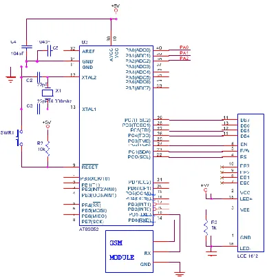
V. EXPERIMENTAL SETUP
12 from the controller is fed to a AE GSM module and to a LCD display. The power supply circuit consists of a step down transformer (230 V/12 V), which steps down the voltage to 12 V AC and further it is lowered to 5 V with the use of a voltage regulator and converted into DC by using a bridge rectifier. It is assembled with a group of resistors representing cable lengths in kilometers.
Fig. 1
R1, R2, R3,R4; R5, R6, R7, R8; and R9, R10, R11, R12 connected in series interlaced with switches connected in parallel between two phase lines as shown in the circuit diagram, represents the line wire system placed underground originating at the base station.
VI. WORKING
The program executes by scanning the three phases in sequence at an interval of one second. If any of the nine switches is found to be faulted then the voltage drop in the in-built ADC of the microcontroller varies depending on the current flow in the transmission line constituting the respective switch. This current is reciprocally proportional to the resistive value of the length of the cable. The voltage is converted into a digital value which is equivalent to the voltage value. This digitalized value which is the distance in kilometers of the cable fault is given as an output to the LCD display to be displayed. The same is also sent on a cell phone whose number has been specified in the code that has been programmed in the microcontroller. The calculated distance can be monitored through a server using a username and a password. The server’s IP address has also been specified in the code too.
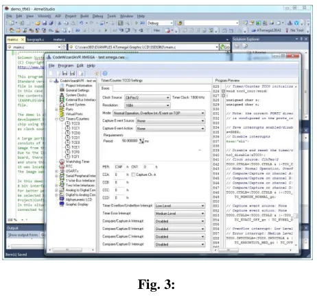
13 VII. COMPILATION SOFTWARE
The CodeVision is generally known as CodeVision AVR C Compiler is developed by Pavel Haiduc. It was designed to make C programming easy for all users. However, the compiler is also designed to support data types and variables that may be used for AVR and C structures.
Code size is limited in the Evaluation version of the CodeVision AVR C Compiler and CodeWizard for the Atmel Tiny, Mega and Xmega AVR 8-bit Microcontrollers. It includes also the LCD Vision font and image editor/converter for graphic displays. It requires Atmel Studio 6.1 or a later version of the same. Both Atmel Studio and CodeVision AVR must be installed and run with Administrator privileges. During Atmel Studio 6.1 installation under Windows XP, the checkbox "Protect my computer and data from unauthorized program activity" must be unchecked.
Fig. 3:
CONCLUSION
This paper constitutes our proposed method of detection of the location of short circuit faults in the underground cables originating at the base station, in kilometers. The method makes use of the AT mega-16 microcontroller as the main controller. This method incorporates the use of the concepts of Ohm’s law to locate the cable faults. We have made use of a GSM module to keep track of the fault distance through a specified server and a specified mobile number.
REFRENCES
[1]. B.Clegg, ―Underground Cable Fault Location. McGraw- Hill, 1993‖.
[2]. Dhivya Dharani.A, Sowmya.T, ―Development of a prototype of Underground Cable Fault Detector‖,IJEECS, Vol-2, 2014. [3]. Dhekale P.M., Prof. Suryawanshi R.R., ―Underground Cable Fault Distance Locator‖, IJIERT, vol-2, April, 2015. [4]. M. S. Choi, D.S. Lee, and X. Yang, ―A line to ground fault location algorithm for underground cable system,‖ KIEE
Trans. Power Eng., pp. 267–273, Jun. 2005.