Adv. Radio Sci., 9, 165–171, 2011 www.adv-radio-sci.net/9/165/2011/ doi:10.5194/ars-9-165-2011
© Author(s) 2011. CC Attribution 3.0 License.
Advances in
Radio Science
Deterministic and stochastic channel models implemented in a
physical layer simulator for Car-to-X communications
J. Nuckelt, M. Schack, and T. K ¨urner
Institut f¨ur Nachrichtentechnik, Technische Universit¨at Braunschweig, Germany
Abstract. This paper presents a physical (PHY) layer
sim-ulator of the IEEE 802.11p standard for Wireless Access in Vehicular Environments (WAVE). This simulator allows the emulation of data transmission via different radio chan-nels as well as the analysis of the resulting system behav-ior. The PHY layer simulator is part of an integrated sim-ulation platform including a traffic model to generate re-alistic mobility of vehicles and a 3D ray-optical model to calculate the multipath propagation channel between trans-mitter and receiver. Besides deterministic channel model-ing by means of ray-optical modelmodel-ing, the simulator can also be used with stochastic channel models of typical vehicular scenarios. With the aid of this PHY layer simulator and the integrated channel models, the resulting performance of the system in terms of bit and packet error rates of different re-ceiver designs can be analyzed in order to achieve a robust data transmission.
1 Introduction
Car-to-car or car-to-infrastructure communications – sum-marized under the term C2X communications – have been of great research interest in recent years. This technology shall contribute to increase the safety as well as the efficiency of road traffic. The dedicated IEEE standard for vehicular communications is 802.11p, also known as WAVE (IEEE, 2010). The European equivalent is the ETSI standard Intel-ligent Transportation Systems (ITS)-G5 (ETSI, 2010). Both standards operate in the 5.9 GHz band and are mainly based on the well-known Wireless Local Area Network (WLAN) standard IEEE 802.11a (IEEE, 2007). Since IEEE 802.11a was primarily designed for nomadic indoor usage it has to be
Correspondence to: J. Nuckelt ([email protected])
ensured that 802.11p will reliably operate in typical vehicular environments with high relative velocities between transmit-ter and receiver as well as long multipath propagation delays. In order to investigate and validate the system performance in different C2X communication scenarios, a PHY layer sim-ulator compliant to IEEE 802.11p has been developed. In this paper, we give a description of the simulator structure and provide an overview of the implemented channel mod-els. Since the characteristic of the C2X radio channel has a huge impact on the system performance and each chan-nel model has its advantages and disadvantages, we intend to use different kinds of channel models for the simulations. On the one hand, a self-developed ray-optical tool is used to model the radio channel deterministically. This approach allows us to analyze the system behavior in a specific situ-ation, e.g. two cars are approaching a certain intersection. On the other hand, the stochastic channel models, which can be found in the literature (Acosta-Marum and Ingram, 2007), are used to investigate the system performance in scenarios that represent a certain C2X communication environment, e.g. a highly mobile highway scenario. In this way, several receiver designs like different channel estimation strategies can be evaluated and compared to each other.
This paper is structured as follows: Sect. 2 gives a detailed description of the developed PHY layer simulator. Section 3 describes the deterministic and stochastic channel models implemented in the simulator. Some performance results in terms of packet error rates are presented in Sect. 4. The paper finally ends with a summary and a conclusion in Sect. 5.
2 Description of the PHY layer simulator
The developed PHY layer simulator is part of an integrated simulation environment for C2X communications as illus-trated in Fig. 1. This simulation platform includes scenario data of the city of Braunschweig, a 3D ray-optical tool to
166 J. Nuckelt et al.: Deterministic and stochastic channel modelling for Car-to-X communications
Fig. 1. Integrated simulation environment for C2X communica-tions.
Manuscript prepared for Adv. Radio Sci.
with version 3.2 of the LATEX class copernicus.cls. Date: 12 November 2010
Deterministic and stochastic channel models implemented in a
physical layer simulator for Car-to-X communications
J¨org Nuckelt, Moritz Schack, and Thomas K ¨urner
Institut f¨ur Nachrichtentechnik, Technische Universit¨at Braunschweig, Germany
Abstract. In this paper, a physical (PHY) layer simulator of
the IEEE 802.11p standard for Wireless Access in Vehicu-lar Environments (WAVE) is presented. With this simulator, the emulation of data transmission via different radio chan-nels and the analysis of the resulting system behavior are possible. The PHY layer simulator is part of an integrated simulation platform including a traffic model to generate re-alistic mobility of vehicles and a 3D ray-optical model to calculate the multipath propagation channel between trans-mitter and receiver. Besides deterministic channel model-ing by means of ray-optical modelmodel-ing, the simulator can also be used with stochastic channel models of typical vehicular scenarios. With the aid of this PHY layer simulator and the integrated channel models, the resulting performance of the system in terms of bit and packet error rates of different re-ceiver designs can be analyzed in order to achieve a robust data transmission.
1 Introduction
Car-to-car or car-to-infrastructure communications – sum-marized under the term C2X communications – have been of great research interest in recent years. This technology shall contribute to increase the safety as well as the efficiency of road traffic. The dedicated IEEE standard for vehicular communications is 802.11p, also known as WAVE (IEEE, 2010). The European equivalent is the ETSI standard Intel-ligent Transportation Systems (ITS)-G5 (ETSI, 2010). Both standards operate in the 5.9 GHz band and are mainly based on the well-known Wireless Local Area Network (WLAN) standard IEEE 802.11a (IEEE, 2007). Since IEEE 802.11a was primarily designed for nomadic indoor usage it has to be ensured that 802.11p will reliably operate in typical vehicular Correspondence to: J¨org Nuckelt
Fig. 1. Integrated simulation environment for C2X communications
environments with high relative velocities between transmit-ter and receiver as well as long multipath propagation delays. In order to investigate and validate the system performance in different C2X communication scenarios, a PHY layer sim-ulator compliant to IEEE 802.11p has been developed. In this paper, we give a description of the simulator structure and provide an overview of the implemented channel mod-els. Since the characteristic of the C2X radio channel has a huge impact on the system performance and each chan-nel model has its advantages and disadvantages, we intend to use different kinds of channel models for the simulations. On the one hand, a self-developed ray-optical tool is used to model the radio channel deterministically. This approach al-lows us to analyze the system behavior in a specific situation, e.g. two cars are approaching an certain intersection. On the
PREAMBLE SIGNAL DATA
10×1.6µs 2×8µs 8µs up to 11 ms
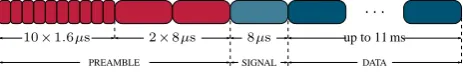
Fig. 2. IEEE 802.11p frame structure with preamble, signal and
data fields
Fig. 2. IEEE 802.11p frame structure with preamble, signal and data fields.
model the radio channel, a road traffic and network simula-tor as well as the PHY layer simulasimula-tor presented in this paper. A more detailed description of the integrated simulation en-vironment can be found in (Schumacher et al., 2009; K¨urner and Schack, 2010). Basically, the part of the PHY layer sim-ulator can be divided into three blocks, namely transmitter, radio channel, and receiver. In the following subsections, the structure of these blocks is described in detail.
2.1 Transmitter
In IEEE 802.11p, data is transmitted as packets as illus-trated in Fig. 2. First, the transmitter creates the Physical Layer Convergence Protocol (PLCP) preamble consisting of 10 short and 2 long training symbols. Depending on the cho-sen data rate and payload size, the subsequent signal field is generated. After that the payload data is appended. In or-der to generate the payload, the transmitter creates randomly distributed binary data which thereafter is scrambled using the generator polynomial S(x)=x7+x4+1. The output of the scrambler passes the convolutional encoder to intro-duce a forward error correction (FEC). The generator poly-nomials of the coder areg0=1338 andg1=1718offering a coding rate of 1/2. Coding rates of 2/3 and 3/4 are gen-erated by employing puncturing patterns. The encoded bi-nary data is interleaved by a two-step permutation algorithm. Afterwards, the data stream is modulated to complex sym-bols, whereas binary phase shift keying (BPSK), quadrature phase shift keying (QPSK), 16- and 64-quadrature ampli-tude modulation (QAM) are defined by the standard, and is then converted from serial to parallel. The data symbols are
mapped to the corresponding subcarriers and four pilot tones are inserted. A 64-IFFT block converts the data from the frequency to the time domain. The IFFT output is parallel-to-serial converted and a guard interval in the form of a cyclic prefix (CP) of a periodTcp=1.6µs is added to overcome the impact of multipath propagation. Several data OFDM sym-bols as well as the signal field and the preamble are merged to a packet that passes the radio channel block. The complete structure of the transmitter block is illustrated in Fig. 3.
2.2 Channel
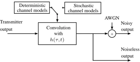
The time-variant frequency-selective radio channel is mo-deled by two stages, namely a tapped-delay line model and an additive white Gaussian noise (AWGN) block. First, a discrete convolution of the transmitted packet and channel impulse response (CIR) is performed. The CIR is updated for each sample period, i.e. T =1/10MHz=0.1µs. The CIR is calculated either by means of 3D ray-optical modeling or derived from the stochastic channel models presented in (Acosta-Marum and Ingram, 2007). The implemented chan-nel models are described in more detail in Sect. 3. After-wards, AWGN with respect to the selected signal-to-noise ratio (SNR) level is added to the signal. The resulting signal is the input of the receiver block. The block diagram of the radio channel implementation is depicted in Fig. 4. Note that the receiver is also fed with a noiseless version of the sig-nal that has only been convolved with the CIR. In this way, reference information like perfect channel knowledge can be obtained at the receiver.
2.3 Receiver
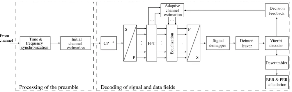
According to the frame structure of IEEE 802.11p, the whole signal processing in the receiver can be divided into two parts: processing of the preamble field and decoding of the signal and data fields. For a better understanding, the struc-ture of the receiver is depicted in Fig. 5. First, the short preamble and the long preamble are used to perform coarse and fine time as well as frequency synchronization. The current version of the implemented simulator performs ideal time synchronization. Coarse and fine frequency synchro-nization is carried out according to the approach presented in (Terry and Heiskala, 2002). Afterwards, an initial estima-tion of the channel transfer funcestima-tion (CTF) based on the long preamble is performed.
In the second step, the signal field is equalized using the initial channel estimate and decoded in order to recover the transmitted information about the current data rate and pay-load size. After that, the OFDM symbols of the data field are decoded. Basically, the receiver performs the inverse signal processing as in the transmitter with some additional steps. First, the CP is removed. The remaining core OFDM sym-bol is converted from serial to parallel and is transformed to the frequency domain by applying a 64-FFT. After that, a
J. Nuckelt et al.: Deterministic and stochastic channel modelling for Car-to-X communications 167
2
J¨org Nuckelt et al.: Deterministic and stochastic channel modelling for Car-to-X communications
Binary
source Scrambler Interleaver
Convolutional coder
Signal mapper
S
S P
P Pilots
IFFT Add
CP
Transmitter output
Fig. 3. Block diagram of the transmitter
other hand, the use of stochastic channel models, which can
be found in the literature (Acosta-Marum and Ingram, 2007),
are used to investigate the system in scenarios that represent a
certain C2X communication environment, e.g. a highly
mo-bile highway scenario. In this way, several receiver designs
like different channel estimation strategies can be evaluated
and compared to each other.
This paper is structured as follows: In section 2, a
de-tailed description of the developed physical layer simulator
is given. Section 3 describes the deterministic and stochastic
channel models implemented in the simulator. Some
perfor-mance results in terms of packet error rates are presented in
section 4. The paper finally ends with a summary and a
con-clusion in section 5.
2
Description of the PHY layer simulator
The developed PHY layer simulator is part of an integrated
simulation environment for C2X communications as
illus-trated in Fig. 1. This simulation platform includes scenario
data of the city of Braunschweig, a 3D ray-optical tool to
model the radio channel, a road traffic and network
simula-tor as well as the PHY layer simulasimula-tor presented in this paper.
A more detailed description of the integrated simulation
en-vironmen can be found in (Schumacher et al., 2009; K¨urner
and Schack, 2010). Basically, the part of the PHY layer
sim-ulator can be divided into three blocks, namely transmitter,
radio channel and receiver. In the following subsections, the
structure of these blocks is described in detail.
2.1
Transmitter
In IEEE 802.11p, data is transmitted as packets as
illus-trated in Fig. 2. At first, the transmitter creates the
Phys-ical Layer Convergence Protocol (PLCP) preamble
consist-ing of 10 short and 2 long trainconsist-ing symbols. Dependconsist-ing on
the chosen data rate and payload size, the subsequent signal
field is generated. After that the payload data is appended.
In order to generate the payload, the transmitter creates
ran-domly distributed binary data which thereafter is scrambled
using the generator polynomial
S
(
x
) =
x
7+
x
4+ 1
. The
output of the scrambler passes the convolutional encoder to
introduce a forward error correction (FEC). The generator
polynomials of the coder are
g0
= 133
8and
g1
= 171
8offer-ing a codoffer-ing rate of
1
/
2
. Coding rates of
2
/
3
and
3
/
4
are
generated by employing puncturing patterns. The encoded
binary data is interleaved by a two-step permutation
algo-rithm. Afterwards, the data stream modulated to complex
symbols, whereas binary phase shift keying (BPSK),
quadra-ture phase shift keying (QPSK), 16- and 64-quadraquadra-ture
am-plitude modulation (QAM) are defined by the standard and is
then converted from serial to parallel. The data symbols are
mapped to the corresponding subcarriers and four pilot tones
are inserted. A 64-IFFT block converts the data from the
frequency to the time domain. The IFFT output is
parallel-to-serial converted and a guard interval in the form of a cyclic
prefix (CP) of a period
T
cp= 1
.
6
µ
s
is added to overcome the
impact of multipath propagation. Several data OFDM
sym-bols as well as the signal field and the preamble are merged
to a packet that passes the radio channel block. The complete
structure of the transmitter block is illustrated in Fig. 3.
2.2
Channel
The time-variant frequency-selective radio channel is
mo-deled by two stages, namely a tapped-delay line model and
an additive white Gaussian noise (AWGN) block. First, a
dis-crete convolution of the transmitted packet and channel
im-pulse response (CIR) is performed. The CIR is updated each
sample period, i.e.
T
= 1
/
10MHz = 0
.
1
µ
s
. On the one hand,
the CIR is calculated by means of 3D ray-optical modeling
or derived from the stochastic channel models presented in
(Acosta-Marum and Ingram, 2007). The implemented
chan-nel models are described in more detail in section 3.
Af-terwards, AWGN with respect to the selected signal-to-noise
ratio (SNR) level is added to the signal. The resulting
sig-nal is the input of the receiver block. The block diagram of
the radio channel implementation is depicted in Fig. 4. Note
that the receiver is also fed with a noiseless version of the
sig-nal that has only been convolved with the CIR. In this way,
Convolution with h(τ,t) Deterministic channel models
Stochastic channel models
AWGN
+ Transmitter
output
output output Noisy
Noiseless
Fig. 4. Block diagram of the radio channel with deterministic and
stochastic channel models
Fig. 3. Block diagram of the transmitter.
2
J¨org Nuckelt et al.: Deterministic and stochastic channel modelling for Car-to-X communications
Binary
source Scrambler Interleaver
Convolutional coder
Signal mapper
S
S P
P Pilots
IFFT Add
CP
Transmitter output
Fig. 3. Block diagram of the transmitter
other hand, the use of stochastic channel models, which can
be found in the literature (Acosta-Marum and Ingram, 2007),
are used to investigate the system in scenarios that represent a
certain C2X communication environment, e.g. a highly
mo-bile highway scenario. In this way, several receiver designs
like different channel estimation strategies can be evaluated
and compared to each other.
This paper is structured as follows: In section 2, a
de-tailed description of the developed physical layer simulator
is given. Section 3 describes the deterministic and stochastic
channel models implemented in the simulator. Some
perfor-mance results in terms of packet error rates are presented in
section 4. The paper finally ends with a summary and a
con-clusion in section 5.
2
Description of the PHY layer simulator
The developed PHY layer simulator is part of an integrated
simulation environment for C2X communications as
illus-trated in Fig. 1. This simulation platform includes scenario
data of the city of Braunschweig, a 3D ray-optical tool to
model the radio channel, a road traffic and network
simula-tor as well as the PHY layer simulasimula-tor presented in this paper.
A more detailed description of the integrated simulation
en-vironmen can be found in (Schumacher et al., 2009; K¨urner
and Schack, 2010). Basically, the part of the PHY layer
sim-ulator can be divided into three blocks, namely transmitter,
radio channel and receiver. In the following subsections, the
structure of these blocks is described in detail.
2.1
Transmitter
In IEEE 802.11p, data is transmitted as packets as
illus-trated in Fig. 2. At first, the transmitter creates the
Phys-ical Layer Convergence Protocol (PLCP) preamble
consist-ing of 10 short and 2 long trainconsist-ing symbols. Dependconsist-ing on
the chosen data rate and payload size, the subsequent signal
field is generated. After that the payload data is appended.
In order to generate the payload, the transmitter creates
ran-domly distributed binary data which thereafter is scrambled
using the generator polynomial
S
(
x
) =
x
7+
x
4+ 1
. The
output of the scrambler passes the convolutional encoder to
introduce a forward error correction (FEC). The generator
polynomials of the coder are
g
0= 133
8and
g
1= 171
8offer-ing a codoffer-ing rate of
1
/
2
. Coding rates of
2
/
3
and
3
/
4
are
generated by employing puncturing patterns. The encoded
binary data is interleaved by a two-step permutation
algo-rithm. Afterwards, the data stream modulated to complex
symbols, whereas binary phase shift keying (BPSK),
quadra-ture phase shift keying (QPSK), 16- and 64-quadraquadra-ture
am-plitude modulation (QAM) are defined by the standard and is
then converted from serial to parallel. The data symbols are
mapped to the corresponding subcarriers and four pilot tones
are inserted. A 64-IFFT block converts the data from the
frequency to the time domain. The IFFT output is
parallel-to-serial converted and a guard interval in the form of a cyclic
prefix (CP) of a period
T
cp= 1
.
6
µ
s
is added to overcome the
impact of multipath propagation. Several data OFDM
sym-bols as well as the signal field and the preamble are merged
to a packet that passes the radio channel block. The complete
structure of the transmitter block is illustrated in Fig. 3.
2.2
Channel
The time-variant frequency-selective radio channel is
mo-deled by two stages, namely a tapped-delay line model and
an additive white Gaussian noise (AWGN) block. First, a
dis-crete convolution of the transmitted packet and channel
im-pulse response (CIR) is performed. The CIR is updated each
sample period, i.e.
T
= 1
/
10MHz = 0
.
1
µ
s
. On the one hand,
the CIR is calculated by means of 3D ray-optical modeling
or derived from the stochastic channel models presented in
(Acosta-Marum and Ingram, 2007). The implemented
chan-nel models are described in more detail in section 3.
Af-terwards, AWGN with respect to the selected signal-to-noise
ratio (SNR) level is added to the signal. The resulting
sig-nal is the input of the receiver block. The block diagram of
the radio channel implementation is depicted in Fig. 4. Note
that the receiver is also fed with a noiseless version of the
sig-nal that has only been convolved with the CIR. In this way,
Convolution with h(τ,t) Deterministic
channel models channel modelsStochastic
AWGN
+ Transmitter
output
output output Noisy
Noiseless
Fig. 4. Block diagram of the radio channel with deterministic and
stochastic channel models
Fig. 4. Block diagram of the radio channel with deterministic and stochastic channel models.
frequency domain channel estimation is performed. On the one hand, the output signal of the channel that is not affected by AWGN can be used to perform an ideal channel estima-tion. On the other hand, the PHY layer simulator is equipped with an adaptive decision-directed (DD) channel estimation technique as presented in (Skupin et al., 2010). Either the ideally or the realistically estimated CTF is used to perform zero-forcing equalization before the signal is again parallel-to-serial converted. In the next step, the complex symbols are demapped to binary data, whereas hard or soft (i.e. ap-proximate log-likelihood ratio (LLR)) decision is performed. Afterwards, the binary data is deinterleaved, decoded by the Viterbi decoder and descrambled. Finally, by a comparison of the originally transmitted data and the decoded received data, the resulting bit and packet error rates are calculated with respect to the current SNR.
In order to validate the results of the PHY layer simula-tor, the simulated BERs in the AWGN channel have been compared to the theoretical values, whereas both match very well.
3 Implemented channel models
Basically, two classes of channel models, namely determin-istic and stochastic models, have been implemented in the PHY layer simulator. The concepts of these models are de-scribed in this section.
3.1 Deterministic channel models
As a deterministic channel model, a 3D ray-optical approach is used in our integrated simulation environment. This model considers the direct path, specular reflections as well as dif-fuse scattering. Specular reflections are calculated with a ray-tracing model based on the image method (McKown and Hamilton Jr., 1991) up to the n-th order, but with respect to the computation time, only first and second order reflec-tions are considered in this investigation. Diffuse scattering is taken into account on surfaces seen by both the transmitter and the receiver. Thus, all surfaces are segmented into tiles and single scattering processes are determined.
For each ray, full-polarimetric antenna patterns are used and channel polarization matrices are computed. The out-put of the ray-optical model for each communication link is a time-variant CIRh(τ,t ), which completely characterizes the frequency-selective channel and can be expressed in the complex baseband as
h(τ,t )=
N (t ) X
k=1
ak(t )·ej (2πf τk(t )+ϕk(t ))·δ(τ−τk(t )) (1)
=
N (t ) X
k=1
ak(t )·δ(τ−τk(t )), (2)
where thek-th multipath component is described by an am-plitudeak(t ), a delayτk(t )and an additional phase shiftϕk(t )
at timet. The number of multipath components, given by
N (t ), is also time-variant. The amplitude and the phase term can be combined for each multipath component in a complex coefficientak(t ), which can be written as
ak(t )=eRx(2Rx,k,8Rx,k)H·Pk
·eTx(2Tx,k,8Tx,k)·Lk(t ),
(3) where the subscriptHdenotes the Hermitian transpose. The complex channel polarization matrix Pk, which is not
nor-malized and thus includes the reflection or scattering losses of the considered path, is multiplied by the complex polariza-tion vectorseRx(2Rx,k,8Rx,k)andeTx(2Tx,k,8Tx,k)for the
Rx and Tx antennas, respectively. These vectors comprise the antenna gains and fully describe the polarization charac-teristics of the antennas at the angles of arrival(2Rx,k,8Rx,k)
168 J. Nuckelt et al.: Deterministic and stochastic channel modelling for Car-to-X communications
J¨org Nuckelt et al.: Deterministic and stochastic channel modelling for Car-to-X communications 3
Processing of the preamble Decoding of signal and data fields From
channel Time & frequency synchronization
Initial
channel
channel
Adaptive estimation
estimation
CP−1
E
q
u
al
izat
io
n
Signal demapper S
S P
P
Deinter-leaver
Viterbi decoder
Descrambler
BER & PER calculation
Decision feedback
FFT
Fig. 5. Block diagram of the receiver
reference information like perfect channel knowledge can be obtained at the receiver.
2.3 Receiver
According to the frame structure of IEEE 802.11p, the whole signal processing in the receiver can be divided into two parts: processing of the preamble field and decoding of the signal and data fields. For a better understanding, the struc-ture of the receiver is depicted in Fig. 5. First, the short preamble and the long preamble are used to perform coarse and fine time as well as frequency synchronization. The current version of the implemented simulator performs ideal time synchronization. Coarse and fine frequency synchro-nization is carried out according to the approach presented in (Terry and Heiskala, 2002). Afterwards, an initial estima-tion of the channel transfer funcestima-tion (CTF) based on the long preamble is performed.
In the second step, the signal field is equalized using the initial channel estimate and decoded in order to recover the transmitted information about the current data rate and pay-load size. After that, the OFDM symbols of the data field are decoded. Basically, the receiver performs the inverse signal processing as in the transmitter with some additional steps. At first, the CP is removed. The remaining core OFDM sym-bol is converted from serial to parallel and is transformed to the frequency domain by applying a 64-FFT. After that, a frequency domain channel estimation is performed. On the one hand, the output signal of the channel that is not affected by AWGN can be used to perform an ideal channel estima-tion. On the other hand, the PHY layer simulator is equipped with an adaptive decision-directed (DD) channel estimation technique as presented in (Skupin et al., 2010). Either the ideally or the realistically estimated CTF is used to perform zero-forcing equalization before the signal is again parallel-to-serial converted. In the next step, the complex symbols are demapped to binary data, whereas hard or soft (i.e. ap-proximate log-likelihood ratio (LLR)) decision is performed. Afterwards, the binary data is deinterleaved, decoded by the Viterbi decoder and descrambled. Finally, by a comparison
of the originally transmitted data and the decoded received data, the resulting bit and packet error rates are calculated with respect to the current SNR.
In order to validate the results of the PHY layer simula-tor, the simulated BERs in the AWGN channel have been compared to the theoretical values, whereas both match very well.
3 Implemented channel models
Basically, two classes of channel models, namely determin-istic and stochastic models, have been implemented in the PHY layer simulator. The concepts of these models are de-scribed in this section.
3.1 Deterministic channel models
As a deterministic channel model, a 3D ray-optical approach is used in our integrated simulation environment. This model considers the direct path, specular reflections as well as dif-fuse scattering. Specular reflections are calculated with a ray-tracing model based on the image method (McKown and
Hamilton Jr., 1991) up to the n-th order, but with respect
to the computation time, only first and second order reflec-tions are considered in this investigation. Diffuse scattering is taken into account on surfaces seen by both, the transmitter and the receiver. Thus, all surfaces are segmented into tiles and single scattering processes are determined.
For each ray, full-polarimetric antenna patterns are used and channel polarization matrices are computed. The out-put of the ray-optical model for each communication link is
a time-variant CIR h(τ,t), which completely characterizes
the frequency-selective channel and can be expressed in the complex baseband as
h(τ,t) =
N(t) X
k=1
ak(t)·ej(2πf τk(t)+ϕk(t))·δ(τ−τk(t)) (1)
=
N(t) X
k=1
ak(t)·δ(τ−τk(t)), (2) Fig. 5. Block diagram of the receiver.
and the angles of departure(2Tx,k,8Tx,k)for thek-th
mul-tipath component. The complex factorLk(t )comprises the
propagation loss and the phase shift based on the delayτ of the considered path. For the direct path, Pk is the identity
matrix, whereas for reflected and scattered paths of the order
n, Pk is calculated according to (Maltsev et al., 2009) using
Pk=R ϕRx,k· n−2
Y
m=0
Rn−m,k·R ϕn−m,k
·R1,k·R ϕTx,k
,
(4)
where
R(ϕ)=
cosϕ sinϕ
−sinϕ cosϕ
(5) is the rotation matrix. The valueϕTx,k characterizes the
an-gle between the normal vector of the incidence plane and the field strength componentEθ at the first reflection or
scatter-ing point, whereasϕRx,k is the angle between the scattering
or reflecting plane andEθ at the last reflection or scattering
point for thek-th multipath component. For multiple reflec-tions or scattering processes, the termϕi,k is the angle
be-tweenEθand the normal vector of the incidence plane at the i-th reflection or scattering point for thek-th multipath com-ponent, respectively. The reflection or scattering matrix is given by
Ri,k=
r⊥i,k ζ1i,k
ζ2i,k rki,k
, (6)
where the elements r⊥i,k andrki,k are the reflection
coeffi-cients of the surface belonging to thei-th reflection or scat-tering point of thek-th multipath component for perpendicu-lar and parallel components of the electric field, respectively. For reflection processes, these elements are determined based on the Fresnel equations, whereas for scattering processes, the values are calculated using the model of a Lambertian
emitter (Degli-Esposti et al., 2007). For the latter, both el-ements are equal. The elel-ementsζ1i,k andζ2i,k are cross po-larization coupling coefficients and are set to zero in this in-vestigation. An extension of this approach for multiple input multiple output (MIMO) systems and an investigation of dif-ferent antenna configurations can be found in (Schack et al., 2010).
Based on 3D building data, which is available for the city of Braunschweig, and a microscopic road traffic simulator, several traffic scenarios in a dense urban area have been cre-ated. These scenarios represent typical traffic situations that are interesting for C2X applications like intersection colli-sion warning or traffic jam assistants. They can be applied in order to investigate how the underlaying system will op-erate in specific situations and under different radio channel conditions, e.g. the impact of non-line-of-sight (NLOS) and line-of-sight (LOS). An example scenario with two oncom-ing cars that cross each other in an urban canyon is depicted in Fig. 6.
The speed of each vehicle is 120 km/h and there are LOS conditions at any time.
One great challenge of C2X communications are the high Doppler shifts due to the relative motion between communi-cating cars. In this scenario, for example, the relative velocity of transmitter and receiver isv=240km/h corresponding to a maximum Doppler shift of
fD,max= v
cfc=1311Hz, (7)
whereasc andfc denote the speed of light and the carrier frequency of 5.9 GHz, respectively. In Fig. 7, the Doppler spectra with respect to the scenario time are depicted. The Doppler shift of the LOS components at ±1311Hz can clearly be observed. Besides the dominant LOS component, lower Doppler shifts caused by reflected and scattered waves are also present. The calculated spectra fit very well with the expected ones.
J. Nuckelt et al.: Deterministic and stochastic channel modelling for Car-to-X communications 169
Tx
Rx
Fig. 6. Exemplary scenario of two oncoming cars in the city of Braunschweig.
J¨org Nuckelt et al.: Deterministic and stochastic channel modelling for Car-to-X communications
5
5 10 15
−1500 −1000 −500 0 500 1000 1500 −80 −70 −60 −50 −40 −30 −20 −10 0
Time in s
D
o
p
p
le
r
sh
if
t
in
H
z
N
o
rm
aliz
ed
p
o
w
er
in
d
B
Fig. 7. Calculated Doppler spectra versus scenario time of two
on-coming cars
5 10 15
0 0.2 0.4 0.6 0.8 1 1.2 1.4 1.6 1.8 −120 −100 −80 −60 −40 −20 0
D
ela
y
in
µ
s
Time in s
N
o
rm
aliz
ed
p
o
w
er
in
d
B
Fig. 8. Power delay profiles of the scenario with oncoming cars
– VTV-Expressway oncoming (EO),
– VTV-Urban canyon oncoming (UCO),
– RTV-Suburban street (SS),
– RTV-Expressway (E)
1,
– VTV-Expressway same direction with wall (ESDWW)
and
– RTV-Urban canyon (UC).
Each scenario is characterized by a more or less dominant
LOS component and several superimposed multipath
compo-nents. All paths are described by a delay value, the relative
path loss, a K factor as well as Doppler-related parameters
like maximum Doppler shift, LOS Doppler component and
the shape of the Doppler spectra. As all Doppler
frequen-cies are scaled to 120 or 140 km/h, these models can be
em-ployed to carry out PHY layer simulations of highly mobile
propagation scenarios. A limitation of these channel models
is the fact that nonstationarity, which is an important issue
for the modeling of C2X radio channels, is not considered
at all. In Fig. 9, a realization of a CTF corresponding to
the RTV-SS scenario is exemplarily shown. The time-variant
1
According to the note in (Ivan et al., 2010), the K factor of the
first path of this channel model has to be changed to 5.3 dB (instead
of -5.3 dB as given).
and frequency-selective character of the typical C2X
prop-agation channel can clearly be observed. The variation of
the radio channel with respect to the time is one of the most
challenging issues when designing robust C2X receivers.
4
Exemplary simulation results
In this section, some exemplary simulation results in terms of
packet error rates (PERs) are presented. The physical layer
of IEEE 802.11p offers a lot of system parameters that can be
modified. For example, the payload size can be chosen up to
4095 Byte leading to different packet periods. The length of
the transmitted packets has a significant impact on the
sys-tem performance. In Fig. 10, the PERs of several packet
lengths are shown for a data rate of 3 Mbit/s. Perfect
chan-nel knowledge was assumed at the receiver and soft-input
Viterbi decoding has been performed. The applied channel
model is the VTV-EO scenario. As it can be observed, the
length of a packet has a considerable impact on the
result-ing performance and, hence, the choice of the payload size
has to be carefully decided with respect to the performance
requirements of the considered application.
Furthermore, a sophisticated receiver design can also
en-hance the performance.
Different concepts of time and
frequency synchronization, channel estimation or diversity
techniques have to be investigated on their suitability in
C2X communication systems. For instance, a soft-decision
demapper in combination with a preamble-based SNR
esti-mation as it is proposed in (Ren et al., 2009) applied in
time-variant and frequency-selective C2X channel has been
com-pared to simple hard decision. The results in terms of PERs
are depicted in Fig. 11. This chart clearly demonstrates that
advanced receiver techniques offer a great potential to
im-prove the system performance.
5
Conclusions
In this paper, a PHY layer simulator compliant to the IEEE
802.11p WAVE standard is presented. This simulator
fa-0 50 100 150 −26 −20 −10 0 10 20 26 −50 −40 −30 −20 −10 0
OFDM symbol
Subcarrier index
N
o
rm
aliz
ed
p
o
w
er
in
d
B
Fig. 9. Realization of a doubly selective channel transfer function
of the RTV-SS scenario
Fig. 7. Calculated Doppler spectra versus scenario time of two on-coming cars.
Furthermore, the corresponding power delay profiles (PDPs) are shown in Fig. 8. As expected, a lot of delayed multipath components due to reflected or scattered waves on surrounding buildings can be observed.
3.2 Stochastic channel models
Besides deterministic channel models also six doubly selec-tive stochastic channel models published in (Acosta-Marum and Ingram, 2007) have been implemented. The authors in (Acosta-Marum and Ingram, 2007) present three vehicle-to-vehicle (VTV) and three roadside-to-vehicle-to-vehicle (RTV) models:
– VTV-Expressway oncoming (EO),
– VTV-Urban canyon oncoming (UCO),
– RTV-Suburban street (SS),
J¨org Nuckelt et al.: Deterministic and stochastic channel modelling for Car-to-X communications
5
5 10 15
−1500 −1000 −500 0 500 1000 1500 −80 −70 −60 −50 −40 −30 −20 −10 0
Time in s
D
o
p
p
le
r
sh
if
t
in
H
z
N
o
rm
aliz
ed
p
o
w
er
in
d
B
Fig. 7. Calculated Doppler spectra versus scenario time of two
on-coming cars
5 10 15
0 0.2 0.4 0.6 0.8 1 1.2 1.4 1.6 1.8 −120 −100 −80 −60 −40 −20 0
D
ela
y
in
µ
s
Time in s
N
o
rm
aliz
ed
p
o
w
er
in
d
B
Fig. 8. Power delay profiles of the scenario with oncoming cars
– VTV-Expressway oncoming (EO),
– VTV-Urban canyon oncoming (UCO),
– RTV-Suburban street (SS),
– RTV-Expressway (E)
1,
– VTV-Expressway same direction with wall (ESDWW)
and
– RTV-Urban canyon (UC).
Each scenario is characterized by a more or less dominant
LOS component and several superimposed multipath
compo-nents. All paths are described by a delay value, the relative
path loss, a K factor as well as Doppler-related parameters
like maximum Doppler shift, LOS Doppler component and
the shape of the Doppler spectra. As all Doppler
frequen-cies are scaled to 120 or 140 km/h, these models can be
em-ployed to carry out PHY layer simulations of highly mobile
propagation scenarios. A limitation of these channel models
is the fact that nonstationarity, which is an important issue
for the modeling of C2X radio channels, is not considered
at all. In Fig. 9, a realization of a CTF corresponding to
the RTV-SS scenario is exemplarily shown. The time-variant
1
According to the note in (Ivan et al., 2010), the K factor of the
first path of this channel model has to be changed to 5.3 dB (instead
of -5.3 dB as given).
and frequency-selective character of the typical C2X
prop-agation channel can clearly be observed. The variation of
the radio channel with respect to the time is one of the most
challenging issues when designing robust C2X receivers.
4
Exemplary simulation results
In this section, some exemplary simulation results in terms of
packet error rates (PERs) are presented. The physical layer
of IEEE 802.11p offers a lot of system parameters that can be
modified. For example, the payload size can be chosen up to
4095 Byte leading to different packet periods. The length of
the transmitted packets has a significant impact on the
sys-tem performance. In Fig. 10, the PERs of several packet
lengths are shown for a data rate of 3 Mbit/s. Perfect
chan-nel knowledge was assumed at the receiver and soft-input
Viterbi decoding has been performed. The applied channel
model is the VTV-EO scenario. As it can be observed, the
length of a packet has a considerable impact on the
result-ing performance and, hence, the choice of the payload size
has to be carefully decided with respect to the performance
requirements of the considered application.
Furthermore, a sophisticated receiver design can also
en-hance the performance.
Different concepts of time and
frequency synchronization, channel estimation or diversity
techniques have to be investigated on their suitability in
C2X communication systems. For instance, a soft-decision
demapper in combination with a preamble-based SNR
esti-mation as it is proposed in (Ren et al., 2009) applied in
time-variant and frequency-selective C2X channel has been
com-pared to simple hard decision. The results in terms of PERs
are depicted in Fig. 11. This chart clearly demonstrates that
advanced receiver techniques offer a great potential to
im-prove the system performance.
5
Conclusions
In this paper, a PHY layer simulator compliant to the IEEE
802.11p WAVE standard is presented. This simulator
fa-0 50 100 150 −26 −20 −10 0 10 20 26 −50 −40 −30 −20 −10 0
OFDM symbol
Subcarrier index
N
o
rm
aliz
ed
p
o
w
er
in
d
B
Fig. 9. Realization of a doubly selective channel transfer function
of the RTV-SS scenario
Fig. 8. Power delay profiles of the scenario with oncoming cars.
J¨org Nuckelt et al.: Deterministic and stochastic channel modelling for Car-to-X communications
5
5 10 15
−1500 −1000 −500 0 500 1000 1500 −80 −70 −60 −50 −40 −30 −20 −10 0
Time in s
D o p p le r sh if t in H z N o rm aliz ed p o w er in d B
Fig. 7. Calculated Doppler spectra versus scenario time of two
on-coming cars
5 10 15
0 0.2 0.4 0.6 0.8 1 1.2 1.4 1.6 1.8 −120 −100 −80 −60 −40 −20 0 D ela y in µ s
Time in s
N o rm aliz ed p o w er in d B
Fig. 8. Power delay profiles of the scenario with oncoming cars
– VTV-Expressway oncoming (EO),
– VTV-Urban canyon oncoming (UCO),
– RTV-Suburban street (SS),
– RTV-Expressway (E)
1,
– VTV-Expressway same direction with wall (ESDWW)
and
– RTV-Urban canyon (UC).
Each scenario is characterized by a more or less dominant
LOS component and several superimposed multipath
compo-nents. All paths are described by a delay value, the relative
path loss, a K factor as well as Doppler-related parameters
like maximum Doppler shift, LOS Doppler component and
the shape of the Doppler spectra. As all Doppler
frequen-cies are scaled to 120 or 140 km/h, these models can be
em-ployed to carry out PHY layer simulations of highly mobile
propagation scenarios. A limitation of these channel models
is the fact that nonstationarity, which is an important issue
for the modeling of C2X radio channels, is not considered
at all. In Fig. 9, a realization of a CTF corresponding to
the RTV-SS scenario is exemplarily shown. The time-variant
1According to the note in (Ivan et al., 2010), the K factor of the
first path of this channel model has to be changed to 5.3 dB (instead of -5.3 dB as given).
and frequency-selective character of the typical C2X
prop-agation channel can clearly be observed. The variation of
the radio channel with respect to the time is one of the most
challenging issues when designing robust C2X receivers.
4
Exemplary simulation results
In this section, some exemplary simulation results in terms of
packet error rates (PERs) are presented. The physical layer
of IEEE 802.11p offers a lot of system parameters that can be
modified. For example, the payload size can be chosen up to
4095 Byte leading to different packet periods. The length of
the transmitted packets has a significant impact on the
sys-tem performance. In Fig. 10, the PERs of several packet
lengths are shown for a data rate of 3 Mbit/s. Perfect
chan-nel knowledge was assumed at the receiver and soft-input
Viterbi decoding has been performed. The applied channel
model is the VTV-EO scenario. As it can be observed, the
length of a packet has a considerable impact on the
result-ing performance and, hence, the choice of the payload size
has to be carefully decided with respect to the performance
requirements of the considered application.
Furthermore, a sophisticated receiver design can also
en-hance the performance.
Different concepts of time and
frequency synchronization, channel estimation or diversity
techniques have to be investigated on their suitability in
C2X communication systems. For instance, a soft-decision
demapper in combination with a preamble-based SNR
esti-mation as it is proposed in (Ren et al., 2009) applied in
time-variant and frequency-selective C2X channel has been
com-pared to simple hard decision. The results in terms of PERs
are depicted in Fig. 11. This chart clearly demonstrates that
advanced receiver techniques offer a great potential to
im-prove the system performance.
5
Conclusions
In this paper, a PHY layer simulator compliant to the IEEE
802.11p WAVE standard is presented. This simulator
fa-0 50 100 150 −26 −20 −10 0 10 20 26 −50 −40 −30 −20 −10 0 OFDM symbol Subcarrier index N o rm aliz ed p o w er in d B
Fig. 9. Realization of a doubly selective channel transfer function
of the RTV-SS scenario
Fig. 9. Realization of a doubly selective channel transfer function of the RTV-SS scenario.
– RTV-Expressway (E)1,
– VTV-Expressway same direction with wall (ESDWW)
and
– RTV-Urban canyon (UC).
Each scenario is characterized by a more or less dominant LOS component and several superimposed multipath compo-nents. All paths are described by a delay value, the relative path loss, a K factor as well as Doppler-related parameters like maximum Doppler shift, LOS Doppler component and the shape of the Doppler spectra. As all Doppler frequencies are scaled to 120 or 140 km/h, these models can be employed to carry out PHY layer simulations of highly mobile propa-gation scenarios. A limitation of these channel models is the fact that nonstationarity, which is an important issue for the modeling of C2X radio channels, is not considered at all. In Fig. 9, a realization of a CTF corresponding to the RTV-SS scenario is exemplarily shown.
The time-variant and frequency-selective character of the typical C2X propagation channel can clearly be observed. 1According to the note in (Ivan et al., 2010), the K factor of the first path of this channel model has to be changed to 5.3 dB (instead of−5.3 dB as given).
170 J. Nuckelt et al.: Deterministic and stochastic channel modelling for Car-to-X communications
6
J¨org Nuckelt et al.: Deterministic and stochastic channel modelling for Car-to-X communications
−5 −2.5 0 2.5 5 7.5 10 12.5 15
10−2
10−1
100
SNR in dB
P
E
R
50 Byte 100 Byte 200 Byte 1000 Byte
Fig. 10. Impact of the payload size on PER performance in the
VTV-EO scenario
−5 0 5 10 15
10−2
10−1
100
SNR in dB
P
E
R
Hard
Approximate LLR
Fig. 11. Performance evaluation of hard and soft (approximate
LLR) decision in the VTV-EO scenario
cilitates the analysis of future C2X communication systems
operating in realistic environments. Deterministic channel
models by means of 3D ray-optical modeling as well as
stochastic channel models derived from an extensive
mea-surement campaign have been implemented in the simulator.
In this way, the influence of the fast-fading characteristic of
typical C2X channels on the system performance can be
ana-lyzed. Since the radio channel is one of the most challenging
issues with respect to PHY layer implementations different
receiver designs can be evaluated in order to develop a
ro-bust receiver design with the aid of this simulator.
Future work will focus on PHY layer simulations of the
implemented determinstic and stochastic channel models.
The results will be evaluated with respect to the advantages
and disadvantages of both channel models.
Acknowledgment
The authors are grateful to the Ministry of Science and
Cul-ture of Lower Saxony for funding this work within the
Con-nected Cars in a ConCon-nected World (C3World) project.
Fur-thermore, they would like to thank Hendrik Hoffmann and
Alexander Tschiene for their valuable support.
References
Acosta-Marum, G. and Ingram, M.: Six time- and frequency-selective empirical channel models for vehicular wireless LANs, Vehicular Technology Magazine, IEEE, 2, 4–11, 2007.
Degli-Esposti, V., Fuschini, F., Vitucci, E. M., and Falciasecca, G.: Measurement and Modelling of Scattering From Buildings, Antennas and Propagation, IEEE Transactions on, 55, 143–153, 2007.
ETSI: Intelligent Transport Systems (ITS); European profile stan-dard for the physical and medium access control layer of Intelli-gent Transport Systems operating in the 5 GHz frequency band, ETSI ES 202 663 V1.1.0 (2010-01), 2010.
IEEE: IEEE Standard for Information Technology – Telecommu-nications and information exchange between systems – Local and metropolitan area networks – Specific requirements – Part 11: Wireless LAN Medium Access Control (MAC) and Physical Layer (PHY) Specifications, IEEE Std 802.11-2007 (Revision of IEEE Std 802.11-1999), 2007.
IEEE: IEEE Standard for Information technology– Telecommunications and information exchange between systems–Local and metropolitan area networks–Specific re-quirements Part 11: Wireless LAN Medium Access Control (MAC) and Physical Layer (PHY) Specifications Amendment 6: Wireless Access in Vehicular Environments, IEEE Std 802.11p-2010, pp. 1–51, 2010.
Ivan, I., Besnier, P., Bunlon, X., Le Danvic, L., Crussiere, M., and Drissi, M.: Influence of propagation channel modeling on V2X physical layer performance, Antennas and Propagation (Eu-CAP), Proceedings of the Fourth European Conference on, pp. 1–5, 2010.
K¨urner, T. and Schack, M.: 3D Ray-Tracing Embedded Into an Inte-grated Simulator for Car-to-X Communications, in: URSI Com-mission B International Symposium on Electromagnetic Theory (EMT-S), Berlin, 2010.
Maltsev, A., Maslennikov, R., Lomayev, A., Sevastyanov, A., and Khoryaev, A.: IEEE 802.11-09/0431r0, 2009.
McKown, J. and Hamilton Jr., R.: Ray tracing as a design tool for radio networks, Network, IEEE, 5, 27–30, 1991.
Ren, G., Zhang, H., and Chang, Y.: SNR estimation algorithm based on the preamble for OFDM systems in frequency selective chan-nels, Communications, IEEE Transactions on, 57, 2230–2234, 2009.
Schack, M., Kornek, D., Slottke, E., and K¨urner, T.: Analysis of Channel Parameters for Different Antenna Configurations in Vehicular Environments, Vehicular Technology Conference Fall (VTC 2010-Fall), IEEE 72nd, pp. 1–5, 2010.
Schumacher, H., Schack, M., and K¨urner, T.: Coupling of simula-tors for the investigation of car-to-x communication aspects, in: IEEE Asia-Pacific Services Computing Conference, APSCC, pp. 58–63, 2009.
Skupin, C., Hofmann, F., Garcia, A., and Nuckelt, J.: Adaptive Channel Estimation for VANETs, in: 7th International Workshop on Intelligent Transportation (WIT 2010), pp. 91–96, 2010. Terry, J. and Heiskala, J.: OFDM Wireless LANs: A Theoretical
and Practical Guide, Sams Publishing, Indianapolis, 2002. Fig. 10. Impact of the payload size on PER performance in the
VTV-EO scenario.
The variation of the radio channel with respect to the time is one of the most challenging issues when designing robust C2X receivers.
4 Exemplary simulation results
This section presents some exemplary simulation results in terms of packet error rates (PERs). The PHY layer of IEEE 802.11p offers a lot of system parameters that can be mod-ified. For example, the payload size can be chosen up to 4095 byte leading to different packet periods. The length of the transmitted packets has a significant impact on the system performance. In Fig. 10, the PERs of several packet lengths are shown for a data rate of 3 Mbit/s. Perfect channel knowl-edge was assumed at the receiver and soft-input Viterbi de-coding has been performed. The applied channel model is the VTV-EO scenario. It can be observed that the length of a packet has a considerable impact on the resulting perfor-mance and, hence, the choice of the payload size has to be carefully decided with respect to the performance require-ments of the considered application.
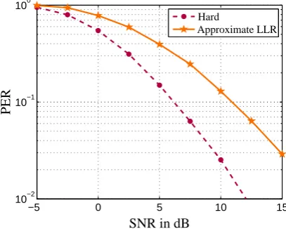
Furthermore, a sophisticated receiver design can also en-hance the performance. Different concepts of time and frequency synchronization, channel estimation or diversity techniques have to be investigated on their suitability in C2X communication systems. For instance, a soft-decision demapper in combination with a preamble-based SNR esti-mation as it is proposed in (Ren et al., 2009) applied in time-variant and frequency-selective C2X channel has been com-pared to simple hard decision. The results in terms of PERs are depicted in Fig. 11. This chart clearly demonstrates that advanced receiver techniques offer a great potential to im-prove the system performance.
6
J¨org Nuckelt et al.: Deterministic and stochastic channel modelling for Car-to-X communications
−5 −2.5 0 2.5 5 7.5 10 12.5 15
10−2
10−1
100
SNR in dB
P
E
R
50 Byte 100 Byte 200 Byte 1000 Byte
Fig. 10. Impact of the payload size on PER performance in the
VTV-EO scenario
−5 0 5 10 15
10−2
10−1
100
SNR in dB
P
E
R
Hard
Approximate LLR
Fig. 11. Performance evaluation of hard and soft (approximate
LLR) decision in the VTV-EO scenario
cilitates the analysis of future C2X communication systems
operating in realistic environments. Deterministic channel
models by means of 3D ray-optical modeling as well as
stochastic channel models derived from an extensive
mea-surement campaign have been implemented in the simulator.
In this way, the influence of the fast-fading characteristic of
typical C2X channels on the system performance can be
ana-lyzed. Since the radio channel is one of the most challenging
issues with respect to PHY layer implementations different
receiver designs can be evaluated in order to develop a
ro-bust receiver design with the aid of this simulator.
Future work will focus on PHY layer simulations of the
implemented determinstic and stochastic channel models.
The results will be evaluated with respect to the advantages
and disadvantages of both channel models.
Acknowledgment
The authors are grateful to the Ministry of Science and
Cul-ture of Lower Saxony for funding this work within the
Con-nected Cars in a ConCon-nected World (C3World) project.
Fur-thermore, they would like to thank Hendrik Hoffmann and
Alexander Tschiene for their valuable support.
References
Acosta-Marum, G. and Ingram, M.: Six time- and frequency-selective empirical channel models for vehicular wireless LANs, Vehicular Technology Magazine, IEEE, 2, 4–11, 2007.
Degli-Esposti, V., Fuschini, F., Vitucci, E. M., and Falciasecca, G.: Measurement and Modelling of Scattering From Buildings, Antennas and Propagation, IEEE Transactions on, 55, 143–153, 2007.
ETSI: Intelligent Transport Systems (ITS); European profile stan-dard for the physical and medium access control layer of Intelli-gent Transport Systems operating in the 5 GHz frequency band, ETSI ES 202 663 V1.1.0 (2010-01), 2010.
IEEE: IEEE Standard for Information Technology – Telecommu-nications and information exchange between systems – Local and metropolitan area networks – Specific requirements – Part 11: Wireless LAN Medium Access Control (MAC) and Physical Layer (PHY) Specifications, IEEE Std 802.11-2007 (Revision of IEEE Std 802.11-1999), 2007.
IEEE: IEEE Standard for Information technology– Telecommunications and information exchange between systems–Local and metropolitan area networks–Specific re-quirements Part 11: Wireless LAN Medium Access Control (MAC) and Physical Layer (PHY) Specifications Amendment 6: Wireless Access in Vehicular Environments, IEEE Std 802.11p-2010, pp. 1–51, 2010.
Ivan, I., Besnier, P., Bunlon, X., Le Danvic, L., Crussiere, M., and Drissi, M.: Influence of propagation channel modeling on V2X physical layer performance, Antennas and Propagation (Eu-CAP), Proceedings of the Fourth European Conference on, pp. 1–5, 2010.
K¨urner, T. and Schack, M.: 3D Ray-Tracing Embedded Into an Inte-grated Simulator for Car-to-X Communications, in: URSI Com-mission B International Symposium on Electromagnetic Theory (EMT-S), Berlin, 2010.
Maltsev, A., Maslennikov, R., Lomayev, A., Sevastyanov, A., and Khoryaev, A.: IEEE 802.11-09/0431r0, 2009.
McKown, J. and Hamilton Jr., R.: Ray tracing as a design tool for radio networks, Network, IEEE, 5, 27–30, 1991.
Ren, G., Zhang, H., and Chang, Y.: SNR estimation algorithm based on the preamble for OFDM systems in frequency selective chan-nels, Communications, IEEE Transactions on, 57, 2230–2234, 2009.
Schack, M., Kornek, D., Slottke, E., and K¨urner, T.: Analysis of Channel Parameters for Different Antenna Configurations in Vehicular Environments, Vehicular Technology Conference Fall (VTC 2010-Fall), IEEE 72nd, pp. 1–5, 2010.
Schumacher, H., Schack, M., and K¨urner, T.: Coupling of simula-tors for the investigation of car-to-x communication aspects, in: IEEE Asia-Pacific Services Computing Conference, APSCC, pp. 58–63, 2009.
Skupin, C., Hofmann, F., Garcia, A., and Nuckelt, J.: Adaptive Channel Estimation for VANETs, in: 7th International Workshop on Intelligent Transportation (WIT 2010), pp. 91–96, 2010. Terry, J. and Heiskala, J.: OFDM Wireless LANs: A Theoretical
and Practical Guide, Sams Publishing, Indianapolis, 2002. Fig. 11. Performance evaluation of hard and soft (approximate
LLR) decision in the VTV-EO scenario.
5 Conclusions
This paper presents a PHY layer simulator compliant to the IEEE 802.11p WAVE standard. This simulator facilitates the analysis of future C2X communication systems operat-ing in realistic environments. Deterministic channel mod-els by means of 3D ray-optical modeling as well as stochas-tic channel models derived from an extensive measurement campaign have been implemented in the simulator. In this way, the influence of the fast-fading characteristic of typical C2X channels on the system performance can be analyzed. Since the radio channel is one of the most challenging is-sues with respect to PHY layer implementations, different receiver designs can be evaluated in order to develop a ro-bust receiver design with the aid of this simulator.
Future work will focus on PHY layer simulations of the implemented determinstic and stochastic channel models. The results will be evaluated with respect to the advantages and disadvantages of both channel models.
Acknowledgements. The authors are grateful to the Ministry of Sci-ence and Culture of Lower Saxony for funding this work within the Connected Cars in a Connected World (C3World) project. Further-more, they would like to thank Hendrik Hoffmann and Alexander Tschiene for their valuable support.
References
Acosta-Marum, G. and Ingram, M.: Six time- and frequency-selective empirical channel models for vehicular wireless LANs, Vehicular Technology Magazine, IEEE, 2, 4–11, 2007.
Degli-Esposti, V., Fuschini, F., Vitucci, E. M., and Falciasecca, G.: Measurement and Modelling of Scattering From Buildings, Antennas and Propagation, IEEE Transactions on, 55, 143–153, 2007.
ETSI: Intelligent Transport Systems (ITS); European profile stan-dard for the physical and medium access control layer of
J. Nuckelt et al.: Deterministic and stochastic channel modelling for Car-to-X communications 171 gent Transport Systems operating in the 5 GHz frequency band,
ETSI ES 202 663 V1.1.0 (2010-01), 2010.
IEEE: IEEE Standard for Information Technology – Telecommu-nications and information exchange between systems – Local and metropolitan area networks – Specific requirements – Part 11: Wireless LAN Medium Access Control (MAC) and Physical Layer (PHY) Specifications, IEEE Std 802.11-2007 (Revision of IEEE Std 802.11-1999), 2007.
IEEE: IEEE Standard for Information technology – Telecommu-nications and information exchange between systems – Local and metropolitan area networks – Specific requirements Part 11: Wireless LAN Medium Access Control (MAC) and Physical Layer (PHY) Specifications Amendment 6: Wireless Access in Vehicular Environments, IEEE Std 802.11p-2010, 1–51, 2010. Ivan, I., Besnier, P., Bunlon, X., Le Danvic, L., Crussiere, M.,
and Drissi, M.: Influence of propagation channel modeling on V2X physical layer performance, Antennas and Propagation (Eu-CAP), Proceedings of the Fourth European Conference on, 1–5, 2010.
K¨urner, T. and Schack, M.: 3-D Ray-Tracing Embedded Into an Integrated Simulator for Car-to-X Communications, in: URSI Commission B International Symposium on Electromagnetic Theory (EMT-S), Berlin, 2010.
Maltsev, A., Maslennikov, R., Lomayev, A., Sevastyanov, A., and Khoryaev, A.: IEEE 802.11-09/0431r0, 2009.
McKown, J. and Hamilton Jr., R.: Ray tracing as a design tool for radio networks, Network, IEEE, 5, 27–30, 1991.
Ren, G., Zhang, H., and Chang, Y.: SNR estimation algorithm based on the preamble for OFDM systems in frequency selective chan-nels, Communications, IEEE Transactions on, 57, 2230–2234, 2009.
Schack, M., Kornek, D., Slottke, E., and K¨urner, T.: Analysis of Channel Parameters for Different Antenna Configurations in Vehicular Environments, Vehicular Technology Conference Fall (VTC 2010-Fall), IEEE 72nd, 1–5, 2010.
Schumacher, H., Schack, M., and K¨urner, T.: Coupling of simu-lators for the investigation of car-to-x communication aspects, in: IEEE Asia-Pacific Services Computing Conference, APSCC, 58–63, 2009.
Skupin, C., Hofmann, F., Garcia, A., and Nuckelt, J.: Adaptive Channel Estimation for VANETs, in: 7th International Workshop on Intelligent Transportation (WIT 2010), 91–96, 2010. Terry, J. and Heiskala, J.: OFDM Wireless LANs: A Theoretical
and Practical Guide, Sams Publishing, Indianapolis, 2002.