460
Copyright © 2011-15. Vandana Publications. All Rights Reserved.
Volume-5, Issue-2, April-2015 International Journal of Engineering and Management Research
Page Number: 460-465
Face Recognition and Detection for Attendance Application
B.Manohar Reddy1, M. Naveen Kumar2, A. Prashanth Reddy3, A. Ravi Teja4, K. Rambabu5, M.C.Chinnaiah6 Department of ECE, BVRIT-Narsapur, INDIA
ABSTRACT
Face identification is one of those challenging problems and up to date, there is no technique that provides a robust solution to all situations and different applications that face identification may encounter.
I. INTRODUCTION
This paper aims at designing an intelligent security system using Face Recognition technology for identifying the user and providing attendance for the user. The system gives feedback on user identification through dialog boxes on PC. The Intelligent system proposed makes use of Mat lab software to achieve the task.The user on facing the USB web camera, the image is captured and compared with facial database present in PC through Lab VIEW software. The feedback on the identity information is displayed on the PC through dialog boxes. The successful users with their verification from database their names are displayed in LCD display which is interfaced with Arduino and their details are stored in excel sheet with their particulars. The users whose face not captured treated as absent or leave and they are intimated a message saying they are absent or leave for that day through GSM module interfaced through Arduino.
Keywords--- Eigen Faces, Histogram, LABVIEW2014
acial recognition system is a computer application for automatically identifying or verifying a person from a digital image or a video frame from a video source. One of the ways to do this is by comparing selected facial features from the image and a facial database. It is typically used in security systems and can be compared to other biometrics such as fingerprint or eye iris recognition systems. Some facial recognition algorithms identify faces by extracting landmarks, or features, from an image of the subject's face. For example, an algorithm may analyse the relative position, size, and/or shape of the eyes, nose, cheekbones, and jaw. These features are then used to search for other images with matching features. Other algorithms normalize a gallery of face images and then compress the face data, only saving the data in the image that is useful for face detection. A probe image is then compared with the face data. Facial recognition systems based on face prints can quickly and accurately
identify target individuals when the conditions are favourable. However, if the subject‘s face is partially obscured or in profile rather than facing forward, or if the light is insufficient, the software isLess reliable. Nevertheless, the technology is evolving quickly and there are several emerging approaches, such as 3D modelling, that may overcome current problems with the systems.
II.
PROJECT IMPLEMENTATION
In this project, we thought of using a web camera as an acquisition device and for analysis we thought of using LABVIEW as it is widely used for Image Processing next to MATLAB. The vision toolbox of LABVIEW is to be installed on the laptop and an image processing algorithm (Histogram Evaluation) is to be done for the recognition of faces. A set of pre-defined images are stored in the database, and the user face will be evaluated with the database if the output value meets the threshold value then it alerts the Arduino which is connected to the USB port of Laptop. Then the respective attendance will be recorded and stored inside the EEPROM of Arduino. A button will be externally interfaced with Arduino, when pressed it will display the list of days present for the respective person on LCD.
461
Copyright © 2011-15. Vandana Publications. All Rights Reserved.
III.
BLOCK DIAGRAM
IV.
VIRTUAL INSTRUMENTATION
A virtual instrument consists of an industry – standard computer of workstation equipped with powerful application software, cost – effective modular hardware such as plug-in boards with appropriate driver software, and the unit under test (UUT) and sensors, all of which work together to perform the function of traditional instruments. Virtual instrument is about redefining what an instrument is and empowering users to build powerful instruments and flexible measurement systems never before possible. Application that incorporates many kinds of I/O, such as data acquisition, motion control, image acquisition, and disturbed I/O. Virtual instruments represent a fundamental shift from traditional hardware-centred instrumentation systems to software-hardware-centred systems that exploit the computing power, productivity, display, and connectivity capabilities of popular desktop computers and workstations. Software is the cornerstone of avirtualinstrumentation system. Its flexibility,
combined with powerful modular hardware solutions, creates the ultimate inuser-defined, scalableinstrumentation systems. Lab VIEW is designed and developed by National Instruments. It provideseasy interface for the programming. It gives us graphical programming with drag and drop functions and online help. LabVIEW provides a platform to develop test and measurement, date acquisition, instrument control, date logging,measurement analysis and report generation applications. Lab VIEW programs are called ‘virtual
instruments ‘or‘VI‘sbecause their appearance and
operation imitate physical instruments such as oscilloscopes and multi meters, indicators andso on.
V.
FACE RECOGNITION
TECHNIQUES
Pattern recognition and matching consists of classifying, processing the input and matching it with a known pattern. Face recognition is a very complex form of pattern recognition. It consists of classifying highly ambiguous input signals, with multiple dimensions and matching them with the know ‘signals‘. Classifying a pattern with high dimensions requires a restrictively large number of training samples. A number of ways have been proposed to solve this problem. Finding an effective means to reduce the dimensionality is the first step in face recognition. Considering the face to be a matrix of values reduces the dimensions to a single dimension. Bit such an approach would be helpful in solving the problem if we were interested in faces that vary by certain transformations, such as magnification translation etc. But biological systems, such as faces do not vary just by transformations, for example changed expression on a face cannot be captured by simple transformations in one -dimensional space.
The design for the Face Recognition System using the Histogram Comparison technique consists 3 main parts.
They are:-
• Providing a GUI (Graphical User Interface) Menu to the user.
• Database Modification.
• Face Recognition by Histogram Technique.
VII.
PROVIDING A GUI (GRAPHICAL
USER INTERFACE) MENU
462
Copyright © 2011-15. Vandana Publications. All Rights Reserved.
Figure 1: Block Diagram for GUI Menu in Lab VIEWWhen the user presses ‘2‘in the GUI Menu that appears at the start of the program, the control is shifted here. An image is taken with the help of the USB Webcam and it is determined whether the person in the picture is there within the authorized people or not. A password authentication system is added to it for additional security.
VII.
DATABASE APPENDING
Generally most Face recognition systems don‘t have the direct flexibility of adding new images to the database, this issue has been taken care of in this design by adding it as an additional feature. The user on his requirement can add new images to the database after going through a test of authentication.
This process contains 2 major steps:-
• Taking an Image from a USB Webcam.
• Storing the image to Database and writing data to Spreadsheet
VIII. ACQUIRING IMAGE FROM USB
WEBCAM
USING NI-IMAQ-USB CAMERA TO
CAPTURE FACE IMAGE
In this project Logitech is used to capture face images and this is because webcam is the most cheapest and due to it availability in common Notebook PC, it is always ready for usage. Web camera using LABVIEW software application will be explained out in details. But first we shall look at the block units used for creating and activating Web Camera to capture an image.
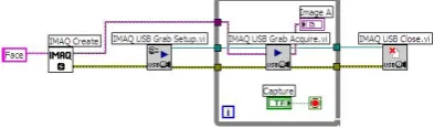
Figure 2: Block Diagram of Capturing Face Images
IX.
USING USB WEB CAMERA
A grab is a continuous, high-speed acquisition of data to a single buffer in host memory. This function performs an acquisition that loops continually on one buffer. We can get a copy of the acquisition buffer by grabbing a copy to a LabVIEW image buffer. We must
use two VIs—IMAQ USB Grab Setup and IMAQ USB Grab Acquire—for a grab acquisition in LabVIEW. Call IMAQ USB Grab Setup once to initialize the acquisition and start capturing the image to an internal software buffer. We can call IMAQ USB Grab Acquire multiple times to copy the image currently stored in the internal buffer to a LabVIEW image buffer. After the program finishes copying images, call IMAQ USB Close once to shut down the acquisition. Figure 2 shows a simplified block diagram for using IMAQ USB Grab Setup and IMAQ USB Grab Acquire.
X.
STORING THE IMAGE TO
DATABASE AND WRITING DATA TO
SPREADSHEET
The image taken from the USB Webcam is stored in the database and after processing that image the characteristic value of the calculated array of the image is written to a spreadsheet file, which is used in the face recognition part of the design.
Figure 3: Block Diagram for Database Appending
XI.
FACE RECOGNITION
When the user presses ‘2’in the GUI Menu that appears at the start of the program, the control is shifted here. An image is taken with the help of the USB Webcam and it is determined whether the person in the picture is there within the authorized people or not. A password authentication system is added to it for additional security. This process contains 3 important parts:-
• Acquiring image from the webcam using NI-IMAQ
• Processing the acquired image and calculating the characteristic value.
• Reading the data from the spreadsheet and comparing it with the current image.
XII.
ACQUIRING IMAGE FROM THE
WEBCAM USING NI-IMAQ
463
Copyright © 2011-15. Vandana Publications. All Rights Reserved.
The above shown block diagram is used to calculate the characteristic value of the image taken from the webcam before the process of comparison starts.
XIII. READING FROM THE
SPREADSHEET FILE AND
COMPARISON
Before going through the block diagram implemented for reading from the spreadsheet and comparing it with the image taken from the webcam, let’s go through the basic units required for building it.
XIV. BLOCK DIAGRAM FOR READING
FROM SPREADSHEET AND
COMPARISON
Using the Read from Spreadsheet VI, the data from the spreadsheet specified in the file path is read. The output of it is provided as an n-dimensional array, using Array Size VI the size of the array coming out of Spreadsheet VI is determined, which is then converted into an integer and it is wired to the count terminal. The spreadsheet array is converted to a one dimensional array using Reshape Array VI. Index Array sub VI is used to access each element of the array individually, it is done by wiring the row and column terminals of the VI, and they are kept in a loop so that one value is retrieved for each iteration of the loop.
This value is compared with value calculated for the image taken from the webcam for a variance level of ‘500‘,based on which it is decided that whether the person in the image exists in the database or not. The output of this block is wired to the password authentication block, if the face recognition is passed then a message is displayed that “FaceRecognition Passed‘, if recognition fails program ends.
XV.
FRONT PANEL FOR FACE
RECOGNITION SYSTEM
464
Copyright © 2011-15. Vandana Publications. All Rights Reserved.
XVII. HARDWARE IMPLEMENTATION
When the power is applied to step down transformer it produces a low voltage of 18 volts DC power which is smaller than input voltage which of 230 volts AC power. The secondary coil of step down transformer is connected to bridge rectifier which in turn produces pulsating DC of 5v power to be used for microcontroller as well as for circuit to be operated. 7805 is the series of voltage regulator which is used to distribute 5v of voltage equally among four ports. These four ports are connected to Arduino, LCD, and USB UART. So if an input image of a person is verified with database then that is intimated to Arduino through USB USART by transmitting a single unique character assigned to that person. Thus displaying name of the person identified in LCD. In similar way the process is continued and all the students or faculty whose verification is verified with database are communicated to Arduino. So after that the students or faculty whose face is not captured is treated as absent. Since they are absent their unique codes are not sent to Arduino which are further sent to GSM module interfaced with Arduino and a message is send to their respective contact numbers saying “YOUR CHILD WAS ABSENT TODAY”.
XVIII.
RESULTS
Using 15 images taken from the webcam connected to computer, the PC based face recognition system is able to achieve up to 88% recognition rate for real time and 93% for standalone systems. This PC based system serves as a proof-of-concept of the proposed face recognition method, which has rooms for further improvements and research. Taking 3 images of a person with different facial expressions and are stored in the database in the form of code books. We took images of 3 persons in the database and if in real time when a person image is taken, system will give output, “FACE RECOGNITION PASSED”, and will display the image of that person present in the database. If he is not present in the database the message “FACE RECOGNITION FAILED”as output. The time taken for recognition is 10 seconds.
XIX. CONCLUSION
This project on Face recognition had given us an opportunity to study about many popular methods used in the field of face recognition. We also came to know that combining two or more techniques can improve the accuracy of system greatly. In this project we have developed a histogram based face recognition system for feature extraction and matching. A reliable face Identification system is an important part of law enforcement, security control and many business processes. It can be used in many applications like office security, attendance, etc. In this project, we explored the possibility of using Lab VIEW for designing an offline face identification system. The system is robust and can detect random, simple and semi-skilled forgeries but the performance deteriorates in case of skilled forgeries. The present study was aimed at evaluating the usefulness of the method. Although it is not the best among all existing methods, there is the possibility of combining it with other methods to achieve better results. Similar to other real world problems, no single approach may solve the face verification problem perfectly, and practical solutions are often derived by combining different approaches. This technique can be added with any existing verification system for better result.
REFERENCES
[1] Image Analysis for Face Recognition‖ Xiaoguang Lu Dept. of Computer Science & Engineering Michigan State University, East Lansing, MI, 48824 [2] A Comparison on Histogram Based Image Matching Methods‘, WenjingJia, Huaifeng Zhang, Xiangjian He,Qiang Wu, University of Technology, Australia. 2006 IEEE International Conference on Advanced Video and Signal Based Surveillance (AVSS'06).
[3] Application of Color Histogram to Human Face Detection‘, Hashem, H.F. Amin, A. Al-Sherbiny, A. AlexandriaHigh Inst. of Eng. & Technol., Alexandria. Information and Communication Technologies: From Theory to Applications, 2008. ICTTA 2008. 3rd International Conference
[4] Rafiquzzaman, M., Microprocessors and microcomputerbased system design, 2nd edition, CRC Press, Inc., 1995
[5] Ronald J.Tocci , Neal S. Widmer, Digital Systems andApplications, 2000 Millennium edition, Prentice Hall
International, Inc. 2000
[6] Albert D. Helfrick& William D. Cooper, Electronic
Instrumentation & Measurement Techniques, 4th Edition, Prentice Hall of India Private Ltd. Reprinted in January 1996
465
Copyright © 2011-15. Vandana Publications. All Rights Reserved.
[8] http://www.ni.com, DAQ 653X User Manual, January 2001Edition, National Instruments Inc.
[9] P. Ryff, Electric Macinery, 2nd edition, McGra Hill