asussial by tn. U. a. uepartmont at Agriculture
Eat Official the
Automatic Furrow Irrigation Systems
F
URROW irrigation systems are more difficult to automate than border and other surface flooding systems, and therefore have received less attention in automatic irrigation development. Border systems are easy to automate because the field topography allows the stream of water to be evenly distributed over the soil surface. When furrows are used, however, the irrigation stream must be uniformly divided into many small streams directed into individual furrows. This requires furrow flow regulating devices or controls, in addi-tion to check and turnout structures. Some of the functions performed by the irrigator in conventional systems, such as adjusting stream sizes, clearing trash, and patrolling the field for leak-age, ditch breaks, and nonuniform water distribution cannot be performed by an automatic system. The need for these checks must be eliminated by system design. Design procedures and methods of system analysis being de-veloped by various investigators (1, 3, 6, 8, 11, 18)' are helpful in accom-plishing this.
Improved irrigation efficiency and water savings from automatic irrigation result from terminating irrigation when the water-holding capacity of the soil is satisfied. Although water savings may be realized, automation usually will be sold because of its convenience and labor- and time-saving features. Differ-ent methods of automatically distribut-ing water into irrigation furrows are dis-cussed in this paper, with emphasis on evaluating an automatic cutback furrow system.
AUTOMATIC CUTBACK FLTRBOW
IRRIGATION SYSTES[
Description and Operation
Because initial soil intake rates are normally high, a large stream is required to wet a furrow through its length in a short period of time. The furrow stream size may be reduced or cut back when the field begins to produce runoff. This can result in a more uniform water
Paper was presented at the xy6c. Pacific Northwest
Region meeting of the American society of Agricultural
Fagirmers in Vancouver, B. C., October Egg. The author is: ALLAN S. HUNIPIIERYS, agricultural engineer, SWCRD, ARS. U. S. Department of Agri-culture, Kimberly, Idaho,
Author': Noir: Contribution from the Northwest Branch, Soil and Water Conservation Research Division. Agricultural Research Service. USDA; Idaho Agricultural Etperiment Station cooperating.
• Numbers is parentheses refer to the appended
references.
A. S. Humpherys
MEMBER ASAE
application with reduced runoff. It is not usually practiced because of the increased labor required and the prob-lem of handling the excess water. Pro-cedures for designing an automatic cut-back furrow irrigation system were presented by Carton (7). When de-signed and operated to satisfy field conditions, this system is very efficient in the use of water. Irrigation labor can be almost eliminated when the semi-automatic drawstring check developed at the USDA Snake River Conservation Research Center is used.
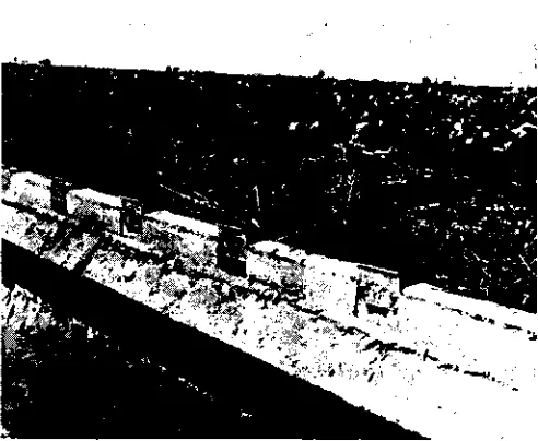
An example of an automatic cutback furrow irrigation system is shown in Fig. 1. Water is distributed to indi-vidual furrows through metal or plas-tic furrow tubes installed in the side of the ditch. Sheet metal orifices and circular and rectangular weir outlets also have been tested for use instead of the furrow tubes (2, 15). Water flows onto the field from two bays or ditch sections simultaneously, with a high initial or primary flow from the down-stream bay outlets and a reduced or cutback secondary flow from the up-stream bay outlets. A timer-controlled check dam placed at the end of each bay releases water into the next bay downstream halfway through the irri-gation set.
Primary and secondary furrow stream sizes can be determined by actual field trials or by procedures outlined by Bishop, et al (3), by Bondurant (4), or Wilkie and Smerdon (17). Furrow streams can be automatically cut back by sequentially towering the water depth over ditch openings as shown in Fig. 1 or by manipulating a supple-mental supply flow as proposed by
Fig. I Automatic cutback furrow irrigation system in concrete lined ditch
Bondurant (4). The supplemental flow, pumped from a storage reservoir or recirculating system or simply a por-tion of the normal farm irrigapor-tion supply, is added to the field supply flow during the primary flow phase of the irrigation. The flow is then auto-matically terminated to reduce the stream size during the secondary flow phase.
The amount of water applied during the same irrigation period will be less
with a cutback system than with a noncutback system. When two groups of furrows, with n furrows in each group, are irrigated with a constant supply flow as shown in Fig. 1 so that the furrow stream is reduced from primary to secondary flow half-way through the irrigation set, the percent-age reduction in the amount of water applied, PQ (no change in time), as compared to irrigation without cutback streams will be
Q Qch .100 —
r
100 [1]
supply flow without cutback streams (and primary supply flow) distributed to 2n fur-rows
Q,b = n( r) q 1 = constant sup-ply flow for cutback system divided into n primary and n secondary furrow streams r = q,/q, where q, = the sec-ondary flow per furrow and q, = the primary flow per furrow (or the flow if no cutback is used).
An automatic cutback system can sometimes be used to improve irriga-tion efficiency in a given field by de-creasing the advance time, thereby enabling a reduction in total time. In this case, the supply flow would be divided into two portions providing a primary flow larger than the original furrow stream size and a secondary flow smaller than the original. Both deep percolation and runoff can be reduced in this way. The percentage of water that can be saved, 13 , (Q constant), by changing the duration of a set with cutback irrigation is:
P , t teb 100 — tR — tact' t
100 [2 1
PQ —
where Q
2
where t tab
to
—
= taeb t„
= contact time required to fill soil root zone
= advance time of the furrow stream from the upper end of the furrow to the lower end with noncutback system
t5,b
=
advance time with cutbacksystem where supply flow is divided into nq, + nq 2 streams
t„ = stream recession time If R te/4, as used by Bishop et al (3), equation [2] can be written
as:
1/R 1/Rcb 1
P
,
= 100[3]
+
1/R — t„/t, where rio = t, /4a,If t„ is small, the term tatc in equation [3] can be neglected. Solu-tions of equation [3] as funcSolu-tions of R and Rob are shown in Fig. 2.
Field Tests
An experimental automatic cutback system was installed at the Research Center to field test timer-controlled structures and to evaluate this type of system. Hooded inlet furrow tubes cut from 1-in. galvanized pipe were in-stalled on 2-ft spacings in the side of an 18-in, deep, experimental steel-lined ditch with three 32-ft level bays. The design supply flow was 0.36 cfs, with a primary furrow stream flow of 8.5 gpm, and a secondary flow of 3.5 gpm. The soil was a silt loam with a 500-ft length of run, and a field slope of about 1 percent.
A second system installed by a farmer in a 2600-ft concrete-lined ditch near Ault, Colorado, was also evaluated. Hooded inlet furrow tubes cut from 2-in, galvanized and 2-in, plastic pipe were installed on 30-in. spacings in the side of the 20-in. deep ditch in bays 73 ft long. The lined-ditch grade ranged from 0.15 to 0.2 percent. The design supply flow was 2.4 cfs, with a
pri-40
A
"
so
I0
MOM
MEE
Elvd—r.
S 4 10Pig. 2 Percent decrease, P,, in the amount of irrigation water applied corresponding to a change from R to Rcb in the required contact
to advance time ratio
mary furrow flow of 27 gpme and
a
secondary flow of 9 gpm. soil was a sandy loam with a field length-of-run of 850 ft and about 3 percent slope. Portable timer-controlled irrigation checks were used in both systems. Those in the Research Center system were left in place during the season, while six units were used along the entire 2600-ft length of the second system. These checks and other timer-controlled structures developed at the Research Center are described else-where (9).Test Results
1nstallation—Installing furrow tubes in the side of a concrete-lined ditch is a problem. The tube locations in a new ditch may be scored before the con-crete sets. Afterwards, holes must be punched in the lining and the tubes grouted in place. Another method used is to push short cylindrical tubes into the "green" concrete. The furrow tubes are ggrrouted in place within these short tubular casings. A satisfactory method of installing furrow tubes in an existing lined ditch has not been developed. Sheet metal orifices and weir notches, and rectangular notches in the top of the lining are less costly to install, but erosion and frost heaving caused by wet soil adjacent to the ditch lining may be problems.
Measurements were taken in the Colorado system to determine elevation variations to be expected during normal installation of furrow tubes in a con-crete ditch and their effect upon the discharge. Using a ponded water
sur-face as a reference, the distance between the top of eighty-seven
2-in.-diameter submerged furrow tube inlets and the water surface was measured. These measurements were taken in four different sections or bays of the ditch. Deviations from the mean tube elevations within each of the bays ranged from zero to 0.54 in., with a standard deviation for all tubes of 0.18 in. Changing the design operating head by ± one standard deviation resulted in only 4 percent variation in computed primary flow discharge and up, to 39 percent variation in secondary flow dis-charge for 2-in, tubes. For 1-in. tubes the computed discharge variations were < 3 percent and < 9 percent, respec-tively. The maximum measured devia-tion of 0.54 in. resulted in discharge variations of < 12 percent and as much as 71 percent for primary and secondary flow, respectively, for 2-in, tubes. Cor-responding variations for 1-in. tubes were < 9 percent and < 30 percent. Thus, elevation errors during installa-tion have a small effect upon the pri-mary flows but are magnified in the secondary flows; the effects are greater with larger tubes. To minimize these
flow variations, above-average care should be exercised during installation. The smallest practical tube size should be used, with the head or water depth over the inlet as large as possible. This should be consistent with other require-ments of the system and without having excessively high and erosive exit veloci-ties. Trash accumulation at the inlet also is minimized if the tube inlets are submerged.
Elevation errors during installation are more critical for rectangular notches and weir crests in the side of a ditch than for orifices and furrow tubes. Greater variations in discharge result because of the weir head-discharge re-lationships. Construction tolerances should be kept as small as possible and the smallest practical notch width used with this type of outlet.
Rigid Design—A disadvantage of the automatic cutback furrow system is its rigid design. A furrow tube spacing must be selected corresponding to the narrowest furrow spacing expected for the crops to be grown. Then, if a sub-sequent crop row-spacing does not correspond with the furrow tube spac-ing, some tubes may be blocked off and not used during a particular season. Bay length is also fixed.
Another problem associated with the system's rigid design is the effect of varying soil intake rates. These vary seasonally and with different cropping and tillage practices. The Research Center system was designed using soil intake rates measured on nearby plots to determine the size of the initial and cutback streams. The first crop irrigated was alfalfa. The stream sizes proved adequate during establishment of the crop when the furrows were clean. However, after the crop was established and the furrow roughness increased, the stream sizes were too small. This some-times resulted in inadequate irrigation at the lower end of the plots.
rate was increased from that existing
at the time the system was designed by
different cultural practices and by the addition of an increased amount of crop residue material. The design stream size was too small at the higher intake rates.
Because changes in soil intake rates are common, the system needs greater flexibility. This can be provided by: (a) using adjustable furrow tubes; or (b) designing for the maximum ex-pected stream size and then providing
a
means of reducing it, if needed. A commercial adjustable plastic furrow tube that can be used is shown in Fig. 3. Inexpensive plastic tube re-ducers which fit on the end of either siphon or furrow tubes also can be used. The reducers shown in Fig. 4 were used in the Research Center sys-tem to slightly reduce the stream size during the 1969 season. When furrow stream sizes are reduced from the de-sign, corresponding changes in the supply flow or lengths of bays must also be made; however, changes in bay lengths are not practical.Field Operation and Irrigation
Effi-ciency—Water application data were analyzed from the Colorado system to determine operational characteristics. The discharge from ten furrow tubes was measured with small V-shaped measuring flumes during both the pri-mary and secondary flow phase of the irrigation with two supply flows. At the approximate design flow rate (-3.4 percent of design flow) the primary
Fig. 3 Adjustable plastic furrow tubes
flow discharge charge was —3.1 per-cent while the secondary flow was —5.3 percent of the design flow. When the supply flow was reduced further so that the primary flow was —18.5 cent, the secondary flow was —51.6 per-cent of the design flow. Thus the system should be operated with the supply flow as near the design flow as possible to minimize secondary flow variations. Water application, runoff and soil moisture data from the Research Center system indicate that an irrigation effi-ciency as high as 75 to 80 percent may be obtained. Higher efficiencies were obtained with some irrigations when timing was optimum. Irrigation dura-tion depends upon the amount of soil moisture depletion. Setting the timer on the semiautomatic checks for the same time each irrigation does not give the same irrigation efficiency when the soil moisture depletion between irriga-tions is different. Alfalfa harvesting op-erations, for example, often interrupt regular irrigation schedules and, con-sequently, soil moisture depletion be-tween irrigations usually is different. Therefore, different irrigation time periods are required. These can be pro-vided with the timer-controlled checks, but are rarely used in normal practice. Runoff from the Research Center sys-tem ranged from 8 to 24 percent. Ex-pressing the runoff from a system using cutback streams as a percentage of the water applied does not give a true comparison with a noncutback system because of the smaller amount applied with the cutback system.
NONCUTBACK FURROW IRRIGATION
SYSTEMS
Outlets in Supply Ditch
The primary problem in automating conventional furrow systems is that of obtaining uniform water distribution in all furrows. One method of doing
this is to place furrow tubes, either plain or gated, in the side of an irrigation ditch similar to the automatic cutback
system. Irrigation is accomplished by increasing the water depth in the ditch until it covers the inlet ends of the tubes and then releasing it into the next section downstream with an automatic structure. Adjustable, or gated, plastic furrow tubes (Fig. 3) have been more satisfactory than galvanized metal tubes.
The moveable slides on the metal tubes tested, after being used for a time, became very difficult to adjust and in many cases were inoperable. Gated tubes usually are adjusted at the beginning of the season and, except for minor adjustments, require no further attention. When plain furrow tubes are used, the plastic flow reducers shown in Fig. 4 may be used for flow adjustment. Lined ditches are normally used be-cause furrow tubes in an unlined ditch interfere with ditch cleaning. When plastic tubes are used, weeds are con-trolled chemically rather than by burn-ing because of possible damage to the tubes.
Notched openings or slots in the top of a lined ditch are sometimes used to admit water into furrows. The system shown in Fig. 5 uses gravel at each outlet to control erosion at the head of each furrow. The last irrigation of the season is completed early enough to allow the soil near the ditch to drain and dry out enough to prevent frost heaving of the lining during the winter. Vee flume-type outlets about 2-ft long placed at the top of a steel lined ditch have also been tested. An advantage over the notch openings is that water is conveyed a short distance from the lining before being discharged into the furrows. Because the openings were close to the top of the ditch, freeboard was limited when water was checked
Fig. 6 Adjustable plastic furrow tubes in a distribution ditch
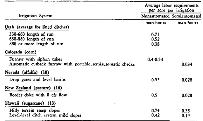
TABLE 2. LABOR REQUIREMENTS FOR CONVENTIONAL NONAUTOMATED AND SEMI-AUTOMATED SURFACE IRRIGATION SYSTEMS.
Irrigation System
Average labor requirements per acre per irrigation Nonautomated Semiautomated
man-hours man-hours Utah (average for lined ditches)
330-660 length of run 0.71
660-880 length of run 0.52
880 or more length of run 0.38
Colorado (corn)
Furrow with siphon tubes 0.9-0.53
Automatic cutback furrow with portable, semiautomatic checks 0.034
Nevada (alfalfa) (10)
0.5 • 0.028 Drop gates and level basins
New Zealand (pasture) (16)
0.5 0.028
Border dyke with 8 cfs flow
Hawaii (sugarcane) (13)
Hilly terrain steep slopes 0.74 0.35
Level-level ditch system mild slopes 0.42 0.14
• Assumed same as for New Zealand system, since both are similar,
to the full depth of the ditch during irrigation.
Feed Ditch or Distribution Bay Systems Furrow tubes or other devices may be placed in a feed ditch or distribu-tion bay adjacent and parallel to the head ditch, Fig. 8. This is usually done with an unlined ditch where it is un-desirable to have the tubes in the head ditch, and also where the head ditch slope is relatively flat. Water is supplied to the distribution ditch through auto-mated border-type openings in the head ditch.
Sheet metal flow controllers inserted in the soil at the upper end of the furrows were tested for controlling the flow into furrows from a distribution ditch instead of sodded outlets. These were made from galvanized sheet metal and had either V-notch, rectangular notch, or circular openings. In some cases, these provided adequate flow control in small corrugates; however, their use is limited to soils that are not erosive and that do not crack excessively between irrigations.
Other Systems
Gated surface pipe and lay-flat tub-ing can be used to distribute water into furrows if a means is provided to sequence the water from one distribu-tion set to another.
An automatic buried pipeline system with a reuse or pumpback system incor-porated has been developed by Fisch-back (5 ). Water is supplied to the
system by automatically controlled pumps with gated surface pipe used for distribution.
A farmer-developed system in south-ern Idaho uses a concrete wall manifold installed near the side of a head ditch or at the outlet of a pipeline. The mani-fold contains a series of small plastic feed pipes which admit water from
it for the next irrigation. The area irrigated was 8.5 acres per set. A suffi-cient number of checks are needed with this system so that they require moving only once or twice each day.
Labor performance data are pre-sented in Table 2 for several types of nonautomated and semiautomated sys-tems using clocks and timers and are indicative of the savings which can result from the use of automated surface irrigation systems. Data from a study conducted in Utah by Strong (14) also are included. The Utah data are an average for lined ditches using concrete turnouts and headgates for both row and sod crops. Labor savings will vary with the length of run, structure spac-ing, field layout, slope, and other fac-tors. The labor required for the auto-matic cutback furrow system is greater than for the Nevada and New Zealand flooding systems because the check dams were portable. If enough checks were used to remain in place, or if permanent structures were used, the labor required would be
less.
Labor requirement data for fully automatic systems are not available. Labor for these systems will be pri-marily that required for periodic inspec-tions, patrolling of the system, and maintenance.
ECONOMICS
Based on the labor savings and instal-lation costs of the 2600-ft Colorado system, an economic analysis was made between an automatic cutback system and one using siphon tubes with a con-crete-lined ditch. The following data were used:
Cost of I8-in. concrete-lined ditch = $1.70/ft
Installation costs for 2 in. furrow the upstream side of the manifold wall
into individual furrows. This system can be operated automatically by checking the water to a depth over the inlet ends of the feed pipe and then auto-matically releasing the water to a level below the feed pipe openings in the manifold wall.
Automatic furrow irrigation systems unique to the irrigation of sugarcane in Hawaii are described by Reynolds
(12).
LABOR REQuatEmErrrs AND SAvnvos
tubes: Material $0.54/tube Installation 1.43/tube
$1.97/tube Structure spacing = 75 ft
Length of run 880 ft Furrow tube spacing = 2.5 ft Cost of semiautomatic check =
$40.00
Minimum irrigation interval = 8 days Average number of irrigations per
year = 7
Irrigator cost = $2.25/hr Minimum labor required:
0.5 man hr/acre per irrigation with siphon tubes
0.034 man hr/acre per irrigation with automatic cutback system and semiautomatic checks Assumed life of concrete lining =
15 years
Assumed life of semiautomatic check = 5 years
Interest rate for amortization = 8 percent
Cost for 80 - 2 in. plastic siphon tubes = $1.02/tube
Cost for 2 manual ditch checks $7.25/check
With these assumptions, the cost of the lined- ditch with tubes installed was $2.49/ft or $124.50/acre. A comparison of the annual fixed and operating costs per acre for the two systems is given in the following tabulation with opera-tion and maintenance costs common to both systems not included:
Siphon tubes Automatic- with
cutback lined system ditch Annual fixed costs/acre $15.38 $10.12 Annual operating ic
maintfacre 0.62 7.93
Total annual cost/acre $16.00 $18.05
The estimated annual operating cost was $2.05/acre less with the automatic cutback system than with siphon tubes. Thus, the cost of the system can be justified from labor savings atone, with all other savings extra. Other potential benefits include: water savings, less fer-tilizer leached, less soil erosion, greater convenience, and in some areas de-creased drainage hazards. Inde-creased crop yields may also be realized on some farms with an improvement in
irrigation efficiency. The per-acre annual fixed costs shown above will vary inversely for other lengths of run. Another way of determining the value of labor saved by automation is to de-termine the present capital investment which can be made to reduce labor costs. The capital investment having an annual repayment cost just equal to the annual labor savings at 8 percent interest for an expected life of 5, 10, and 15 years is shown in Fig. 7.
SUMMARY
Methods and techniques are being developed for automating furrow irri-gation systems to achieve more efficient water use and to save labor. One way of accomplishing this is with an auto-matic cutback furrow irrigation system. The amount of water applied and the surface runoff can be reduced when cutback furrow streams are used. An evaluation of two automatic cutback field installations using semiautomatic check dams indicated that the secondary or cutback streamflow was sensitive to head variations caused by a varying supply flow and furrow inlet elevation errors. To minimize these variations, furrow tubes or inlet openings should be installed as close to design elevation as possible and the system operated with the design supply flow. The sys-tem should be designed with flexibility in adjusting stream sizes to compensate for soil intake rate variations. With proper timing, irrigation efficiencies of 75 to 80 percent can be obtained.
UMW
n
•
n
NE
111111M11
MOEN
MN=
0 $ 2. $4 is is isa
ESTRWED ANNUAL LABOR SAVINGS PER ACRE
Fig. 7 Present investment at II percent interest which can be made to save annual irrigation labor costs for an expected life of 5, 10 and 15 years
Noncutback furrow irrigation sys-tems can be automated by using furrow tubes, gated pipe or other devices for water distribution into furrows and automatic structures for sequencing the water supply from one set to another. Labor requirements can be reduced
as much as 90 percent using semiauto-matic systems. An economic analysis indicated that an automatic cutback furrow irrigation system will pay for itself from labor savings alone. Other benefits such as water and fertilizer savings and convenience are extra.
References
Allen, J. B., Chang, C. T. and Alcantara, V. F. A quantitative analysis of furrow irrigation. ASAE Paper No. 69-m6, ASAE, St. Joseph, Mi 49085, 1969• 2 Barefoot, A. D. and Garton, J. E. The hydraulic properties of sheet metal orifices and circular weirs when used as furrow metering devices on concrete irrigation ditches. Presented at the Southwest Section Annual Meeting of the ASAE, April 1968.
Rishon, A. A., Jensen, M. E. and Hall. W. A. Surface irrigation systems. In: Irrigation of agricultural lands, American Society of Agronomy Monograph No. t1, Madison, Wis., pp. 865-884, 1967.
4 Bondurant, J. A. Design of recirculating irrigation systems. Transactions of the 414E m(2) 365-t66. 201, 19619.
5 Fischbach, Paul E. Design for an automated sur-face irrigation system. In: Automation of irrigation and drainage systems, National Irrigation and Drainage Specialty Conference of the ASCE, pp. 216-236,
November s968.
6 Fob, Y. S. and Bishop, A. A. Expressing the irrigation efficiency in terms of application time, intake and water advance constants. Transaction, of the 454E.
115(4) 438-442, 1969.
7 Carton, I. E. Designing an automatic cut-back
furrow irrigation system. Oklahoma State University Bulletin 13-65t, so October 1966.
8 Hart, W. 5., Bassett, D. L. and &rawer. T. Surface irrigation hydraulics-kinematics. Journal of the Irrigation and Drainage Division, ASCE, Vol. ea, No. 16.4, Proc. Paper Ms, pp. 419-440, December 1968• Hum pherya, A. S. Mechanical structures for farm irrigation. Journal of the irrigation and Drainage Division, ASCE, Vol. 95, No. IR4, Proc. Paper 6944, PP, 463-479, December, [969.
10 Kimberlin, Leon. Automatic basin system reduces irrigation water and labor needs. Soil Conservation 325(2) 39.40, September 1966.
t1 Myers, R. G. and Edwards, D. M. Moisture sensor placement for regulation of furrow irrigation systems.
Trantactions of Me .4545. 13:(3) 303-306. 1970.
is Reynolds, W. N. Automatic surface irrigation in Hawaii. In Automation of irrigation and drainage systems, National Irrigation Specialty Conference of the ASCE, pp. aos-atS, November 1968.
13 Reynolds, W. N. Hawaiian Sugar Planters' Asso-ciation, Honolulu, Hawaii, personal communication, 1968.
14 Strong, D. C. Economic evaluation of alternative facilities for surface and sprinkler irrigation in Utah. Utah State University Agricultural Experiment Station Bulletin 433, ay pp., 1962.
[5 Sweeten, J. M. and Garton, J. E. The hydraulics of an automated furrow irrigation system with rec-tangular side weir outlets. Transaction, of the 4545
135(6)746-751. 1970.
36 Taylor, A. R. Notable Advance in AUSIX12.111C Irri-gation. Hew Zealand Journal of Agricultue, Milk) 67-69, 71. September 1965.
Ty Wilkie, 0. C. and Smertion, E. T. A hydrodynamic determination of cutback stream sizes for irrigation furrows. Transactions of the 454E. 124(5) 634 .637,
1969,
Witlardson, L. S. and Bishop, A. A. Analysis of surface irrigation application efficiency. journal of the Irrigation and Drainage Division. ASCE, Vol. 93. No. 1Rx, Pron. Paper 9267, pp. 21.36, June 067.
# lace 060 110