AUT J. Elec. Eng., 49(2)(2017)151-160 DOI: 10.22060/eej.2017.11535.4974
Investigating Direct Torque Control of Six-Phase Induction Machines Under Open
Phase Fault Conditions
R. Kianinezhad and A. Hajary
Department of Electrical Engineering, Shahid Chamran University of Ahvaz, Ahvaz, Iran.
ABSTRACT: This paper presents analysis and evaluation of classical direct torque control (DTC), for controlling a symmetrical six phase induction motor (SPIM) under open phase fault conditions. The machine has two three-phase windings spatially shifted by 60 electrical degrees. The strategy of the proposed method consists of choosing the switching modes according to the configuration of living phases in such a way that it generates vectors that have higher amplitude in α-β plane while their projections on z axis give zero or near zero amplitude vectors. The goal is reducing parasitic currents and torque ripples of SPIM under faulty mode. Based on the theoretical analysis, it will be shown that in the open phase fault conditions, the only non-pulsating operation is obtained by opening the fault three-phase winding. Experimental test results are provided o support theoretical analysis in open phase fault conditions for SPIM.
Review History: Received: 11 April 2016 Revised: 27 August 2017 Accepted: 27 August 2017 Available Online: 17 September 2017
Keywords:
six phase induction machine direct torque control open phase fault
1- Introduction
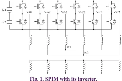
Electrical ac machines have found wide applications in the high power industries. In these cases, we need a high power and high switching frequency semiconductors. In the case that the necessary devices are unavailable, the power is divided among more than three inverter legs to reduce semiconductor ratings. In the multi-phase drive systems, the current per phase in the machine and the inverter is reduced. The most common multi-phase machine drive structure is the six- phase induction machine (SPIM), which has two sets of three-phase windings spatially shifted by 60 electrical degrees (Figure 1). In this structure, the loss of one machine’s phase does not prevent the machine from working, thus, improving the system reliability [1].
One of the most important faults in the electrical drives is the suppression of one or more stator phases of the motor. This fault disturbs the rotating MMF and produces a high pulsating torque [2]. As the dynamic behaviour of the electrical machines is very important in the modern drive systems, it is essential to develop a control method to improve the behaviour of the machine under open phase fault conditions. This paper introduces SPIM control under open phase fault conditions by DTC. Over almost a decade, several schemes have been proposed for the operation of multi-phase induction machines under open phase fault conditions based on FOC [3-5]. In FOC structure and post fault situation, the task of controllers is complicated that need to become a resonant [4] or include feedforward terms [6]. Current references also should be modified in order to obtain a sinusoidal rotating MMF [7-8] and minimum torque pulsations [3-9].
To simplify the control scheme and to improve the dynamic
performance by eliminating the current control loops, one may propose a DTC solution as an alternative to FOC schemes. Unlike FOC, DTC does not tend to duplicate the electromechanical behaviour of a dc motor drive but is aimed at a complete exploitation of the flux and torque-producing capabilities of an induction machine fed by an inverter. In this regard, DTC can be viewed as a novel technique for controlling the induction machine drive under fault conditions.
In this paper, the control of SPIM by DTC in the open phase fault conditions is investigated. This paper is organized into six sections. The model of the machine is presented in the next section. The control method by DTC will be discussed in section 3. Section 4 introduces the control of SPIM by DTC in normal and open phase fault conditions by experimental results. Finally, some conclusions and perspectives will be given in Section 5.
2- MODEL OF SPIM
2- 1- Model in the normal operation
The model of SPIM under normal operating conditions has The corresponding author; Email: [email protected]
been demonstrated in [2]. In the normal mode, the SPIM is a double-six-dimensional system (six stator and six rotor variables). It is shown in [10] that the SPIM model can be decomposed into three two dimensional orthogonal
subspaces, namely (α, β), (z1, z2), and (z3, z4), as follows:
Machine model in α-β subspace
The stator and rotor voltage equations are:
With: Ls=Lls+M , Lr=Llr+M , M=3Lms
This model is similar to the three phase machine model in the stationary reference frame.
Machine model in z1-z2 subspace
Machine model in z3-z4 subspace
As can be seen from these three subsystems, the electromechanical energy conversion takes place only in
α-β subsystem, and the other subsystems do not make any
contribution in the energy conversion. The z1-z2 and z3-z4 subsystems generate the only losses that should be controlled to be minimized. It can be concluded that the torque and speed controller structure and analysis for SPIM are almost the same as those for three-phase induction machines. Therefore,
we use the equivalent model in α-β subspace.
2- 2- Model in the open phase fault condition
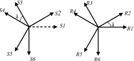
The model of SPIM under the opening phase 1 condition is presented in [3] (see Figure 2).
As shown in Figure 2, the SPIM machine is a five-dimensional system in the stator when one of the stator’s phases is opened. Meanwhile, the rotor will be modeled as a six-dimensional system.
The block-decoupled model of SPIM in α1-β1 and z1-z2-z3
subspaces are as follows:
α1-β1 subspace: The stator and rotor voltage equations for this subsystem are given by
where Rs and Rr are the stator and rotor resistances. The variables ysa1, ysb1, yra1 and yrb1 are a1− b1 components the stator and the rotor fluxes and are described as follows:
where Lr is the rotor inductance and wr is the rotor angular speed. Table 10 gives Lsd, Lsq, Md and Mq for all cases up to three open phases (N = 5, 4 and 3). It can be noticed that the
SPIM model in α-β subspace is always the same as that in (1),
whatever the open phases are.
z1-z2-z3 subspace: The stator voltage equations are:
It can be concluded from (3) and (7) that only the z subspace is related to the losses. Therefore, a suitable control strategy is required to minimize the z1-z2-z3 currents.
Torque Expression Under Open Phase Fault Conditions It is known that the electromagnetic torque oscillates with a faulty open phase. Torque response in the faulty mode operation is as follows [3]:
0 0 0 0 . 0 0 + + = + − − + s s s s s s s s r
r r r r r
r
r r r r r
i
r L p Mp
v
i
r L p Mp
v
i
Mp M r L p L
i
M Mp L r L p
a a b b a b w w w w (1) (2a) (2b) (4a) (4b) (5) (6) (7) (8a) (8b) (8c) (3a) (3b) 1 1 2 2 0 . 0 + = +
sz s ls sz
sz s ls sz
v r L p i
v r L p i
1 2 0 0 . 0 0 + = +
r lr rz
r lr rz
r L p i
r L p i
3 3 4 4
0
.
0
+
=
+
sz s ls sz
sz s ls sz
v
r L p
i
v
r L p
i
3 4
0
0
.
0
0
+
=
+
s ls rz
s ls rz
r L p
i
r L p
i
S2 ã S3 S5 S4 S6 S1 ã R3 R5 R1 R2 R4 R6
Figure 2. Stator and rotor winding axes (s1 is opened).
1 1 1
1 1 1
. . = + = +
s s s s
s s s s
d
v R i
dt d
v R i
dt
a a a
b b b
y
y
1 1 1
1 1 1
0
.
.
0
.
.
=
+
+
=
+
−
r r r r r
r r r r r
d
R i
dt
d
R i
dt
a a b
b b a
y
w y
y
w y
1 1 1
1 1 1
=
+
=
+
s sd s d r
s sq s q r
L i
M i
L i
M i
a a a
b b b
y
y
1 1 1
1 1 1
=
+
=
+
r d s r r
r q s r r
M i
L i
M i
L i
a a a
b b b
y
y
1 1 1 2 2 2 3 3 3.
.
.
=
+
=
+
=
+
szsz s sz ls
sz
sz s sz ls
sz
sz s sz ls
di
v
R i
L
dt
di
v
R i
L
dt
di
v
R i
L
dt
(
)
m 1. 1 1. 1
Γ = q s r − d s r =Γmean+ Γoscil
r
p M i M i
L b ya a y b
(
)
(
)
( )
2 2
1 2
2 2 2 2
1
1 1 sin
cos 2
Γ = + ⋅ − −
+ ⋅
mean d q r s
r
r r
d q
p M M I I L D
M I M I
a b
a b
τ w ϕ ϕ
τ w ϕ
(
2 2 2 2)
(
)
1
cos 2 2
Γ = r r − ⋅ −
oscil d q s
r
p M I M I
Equation (8) shows that in the case of open phase fault, the electromagnetic torque may be decomposed into two components, namely an average component and the other one oscillating at twice the excitation frequency qs (second harmonic).
In the open phase fault conditions, the dynamical properties of the machine will change from its balanced operating conditions, and field-oriented control strategies or direct torque control methods developed for a balanced winding structure will no longer work correctly. In what follows, DTC of SPIM under the condition of open phase fault is investigated.
3- PROPOSED DTC METHOD
3- 1- DTC in the normal conditions
In [12], the DTC of SPIM in the normal mode has been described. The phase voltages of SPIM with respect to its neutrals are as follows:
By combinational analysis of all states of 12 inverter keys, a total of 64 switching modes are obtained. By applying the proper transformation, 64 voltage vectors are projected on the
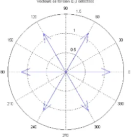
α-β, z1-z2 and z3-z4 subspaces. Figure 3 shows the selected space voltage vectors on the α-β plane for the SPIM.
The decimal numbers in the Figure 3 show switching states of the inverter switches. By converting each decimal number to a six digit binary number, the 1’s indicate the state of the upper switch in the corresponding arm of the inverter. The most significant bit (MSB) of the number represents the switching state of phase a1, the second MSB for the phase a2, the third for phase b1, and so on. Thus, by selecting the space voltage vector according to Table 1, the stator flux and electromagnetic torque of machine can be controlled [12].
3- 2- Analyzing DTC in the open phase fault condition In this section, the DTC of SPIM under the condition of opening one or more phases is investigated. In the open phase fault, the neutrals of the machine will be connected to each other and the configuration of machine changes to one common neutral. In the open phase 1, the phase voltages of the machine with respect to its neutral will be written as follows:
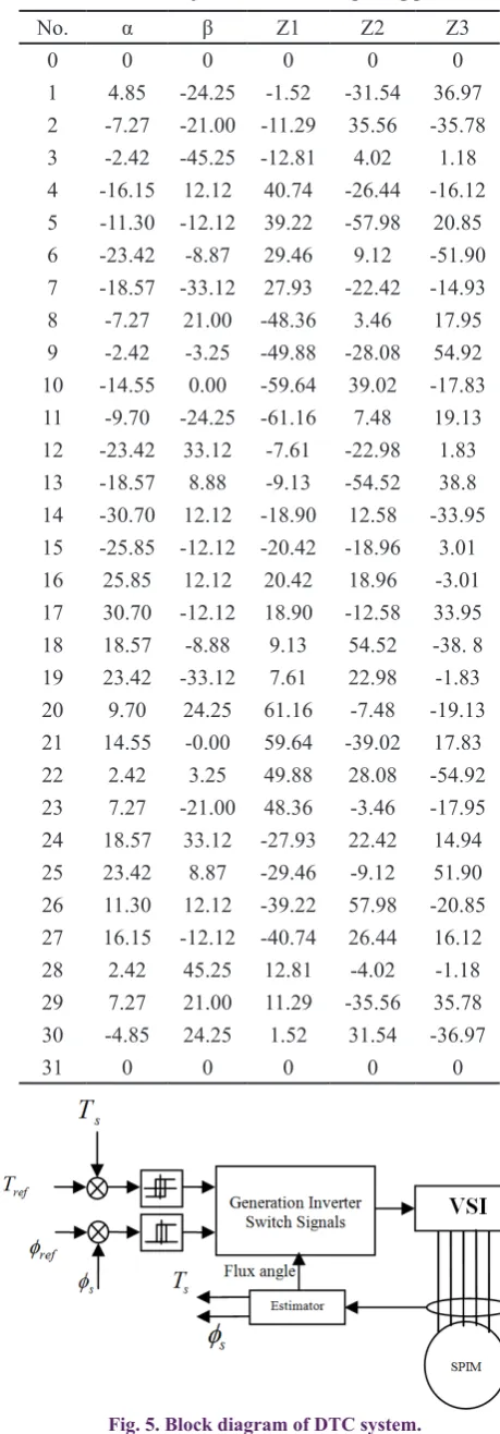
In this case, a total of 32 switching modes can be obtained. By applying a proper five-dimensional transformation, 32
voltage vectors on the α, β, z1, z2, and z3 coordinates will
be obtained. Table 2 shows the projected space voltage
vectors on the α, β, z1, z2, and z3 coordinates.
From Table 2, one cannot find any α-β projected component
with corresponding zero components on the z1, z2, and z3 axes. Each selected space voltage vectors produces high power losses due to non-zero projection on the z1, z2, and z3 axis. To study more open phase conditions and apply DTC, the projection of space voltage vectors on the decoupled spaces by a proper transformation matrix is needed.
Opening one phase (phase 1): In this case, SPIM model is transformed to an asymmetrical five-phase machine. The projected space voltage vectors (SVV) on a five-dimensional decoupled space is shown in Table 2.
Opening two phases: In this case, one may recognize three different opening phase configurations, which are opening phases 1 and 2 (phases 1, 2), opening phases 1 and 3 (phases 1, 3), and opening phases 1 and 4 (phases 1, 4).
In all three cases, SPIM is transformed to an asymmetrical four-phase machine. The projected space voltage vectors on a four-dimensional decoupled space are shown in Tables 3-5. Opening three phases: In this case, one may recognize three different configurations for opened phases, that are phases 123, phases 124, and phases 135. In the first and second case, SPIM transforms to an Asymmetrical three-phase machine, and in the opening three-phases 135, the SPIM transforms to a symmetrical three-phase machine. The projected space voltage vectors to a three dimensional decoupled space are shown in Tables 6 to 8. It seems from
Tables 3 to 7, for every non-zero projection on the α and β axes, one may not find zero or near zero components
on the z-axis. In this case, the root mean square (rms) of total z-axis component voltages is introduced as a norm for (9)
(10)
(
)
1 1
1 2 2 2 2
2
2 2 2 2 2
2
tan , tan and
1 ( )
1 (
with
) 4
− −
= =
+ −
= + − +
r s
r s
r r s
r r s r s
D
τ w
ϕ ϕ τ w
τ w w
τ w w τ w
1 1 3 2 1 1 1
1 1 3 2 1 1 1
1 1 3 2 1 1 1
2 1 3 2 2 2 2
2 1 3 2 2 2 2
2 1 3 2 2 2 2
=
=
=
=
=
=
Va n / * [ *Va o -Vb o -Vc o] Vb n / * [ *Vb o -Va o -Vc o] Vc n / * [ *Vc o -Vb o -Va o]
Va n / * [ *Va o -Vb o -Vc o]
Vb n / * [ *Vb o -Va o -Vc o]
Vc n / * [ *Vc o -Vb o -Va o]
Fig. 3. Selected voltage vectors in the α-β subspace.
Sector
1 2 3 4 5 6
Uλs UTe
1 1 56 28 14 7 35 49
1 0 0 0 0 0 0 0
1 -1 35 49 56 28 14 7
0 1 28 14 7 35 49 56
0 0 63 0 0 0 0 0
0 -1 7 35 49 56 28 14
Table 1: Stator flux and electric torque control for SPIM
Vb1n 1/ 5*[4*Vb1o- Vc1o- Va 2o- Vb2o- Vc2o] Vc1n 1/ 5*[ - Vb1o 4*Vc1o- Va 2o- Vb2o- Vc2o] Va 2n 1/ 5*[-Vb1o- Vc1o 4*Va 2o- Vb2o- Vc2o] Vb2n 1/ 5*[-Vb1o- Vc1o- Va 2o 4*Vb2o- Vc2o] Vc2n 1/ 5*[-Vb1o- Vc1o- Va 2o- Vb2o 4*Vc2o]
=
= +
= +
= +
= +
comparing different switching states of SPIM in the view point of losses under open phase fault conditions. Tables 11 to 13 give rms values of total z-axis component voltages in the case of opening phase 1, phases 1 and 2, phases 1 and 3, and phases 1 and 4.
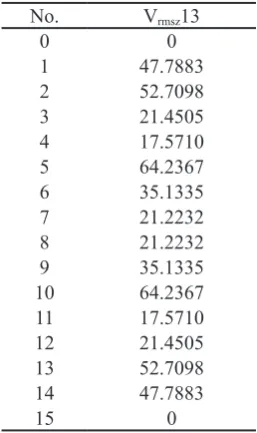
As can be seen , the minimum harmonic voltage in the case of opening phase 1 is 13.47 V, in the case of opening phases 1& 2 is 11.1243 V, in the case of opening phases 1 & 3 is 17.5710 V, and in the case of opening phases 1 & 4 is 11.1155 V. Only in the case of opening three phases with 120 electrical degrees (opening phases 135), can we find a symmetrical three-phase system with zero total harmonic voltage. On the other hand, except for open phase condition 135, DTC cannot control the machine properly in the open phase fault conditions.
4- Test Results
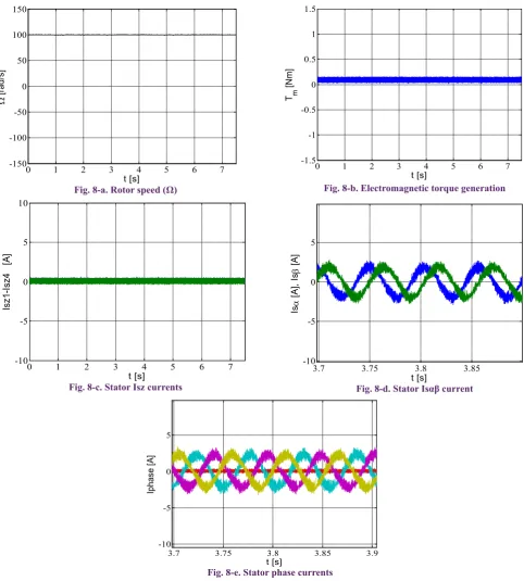
In order to investigate DTC for controlling SPIM due to an opened stator phase fault, an experimental test-rig bed is developed (Fig. 4). The experimental setup is composed of a low power SPIM supplied by two three-phase voltage source inverters whose DC link voltage is fixed at 42 V. The switching frequency is imposed at 5 kHz using the classical sampled natural PWM technique generated by a FPGA. This board receives the stator current data through six 12-bit A/D converters. An electromagnetic power brake stiffly connected to the SPIM rotor shaft is used to generate the load torque. The speed is measured through a 4096-points encoder. The SPIM drive main parameters are given in Table 9. In order to open phase s1, the corresponding VSI winding connection is removed. Figure 5 shows the block diagram of the DTC technique. We use inverse DTC method addressed in [13]. Fig. 6 shows experimental results for DTC method in the normal condition, while Fig. 7 shows experimental results for DTC method in the fault condition (phase s1 open). As can be seen from Fig. 7, low-frequency ripples appear on the angular speed, but its oscillations rate is very low thanks to the mechanical subsystem natural filtering. Fig. 8 illustrates experimental results for DTC method in the fault condition (phases s1, s3, and s5 are open). As can be observed from Fig. 8, the harmonic currents due to projected voltage vectors on the z-space are almost zero, because of zero voltage projection on the z-space in this case.
Fig. 4. Experimental test-rig. Fig. 5. Block diagram of DTC system.
No. α β Z1 Z2 Z3
0 0 0 0 0 0
1 4.85 -24.25 -1.52 -31.54 36.97 2 -7.27 -21.00 -11.29 35.56 -35.78 3 -2.42 -45.25 -12.81 4.02 1.18 4 -16.15 12.12 40.74 -26.44 -16.12 5 -11.30 -12.12 39.22 -57.98 20.85 6 -23.42 -8.87 29.46 9.12 -51.90 7 -18.57 -33.12 27.93 -22.42 -14.93 8 -7.27 21.00 -48.36 3.46 17.95 9 -2.42 -3.25 -49.88 -28.08 54.92 10 -14.55 0.00 -59.64 39.02 -17.83 11 -9.70 -24.25 -61.16 7.48 19.13 12 -23.42 33.12 -7.61 -22.98 1.83 13 -18.57 8.88 -9.13 -54.52 38.8 14 -30.70 12.12 -18.90 12.58 -33.95 15 -25.85 -12.12 -20.42 -18.96 3.01 16 25.85 12.12 20.42 18.96 -3.01 17 30.70 -12.12 18.90 -12.58 33.95 18 18.57 -8.88 9.13 54.52 -38. 8 19 23.42 -33.12 7.61 22.98 -1.83 20 9.70 24.25 61.16 -7.48 -19.13 21 14.55 -0.00 59.64 -39.02 17.83 22 2.42 3.25 49.88 28.08 -54.92 23 7.27 -21.00 48.36 -3.46 -17.95 24 18.57 33.12 -27.93 22.42 14.94 25 23.42 8.87 -29.46 -9.12 51.90 26 11.30 12.12 -39.22 57.98 -20.85 27 16.15 -12.12 -40.74 26.44 16.12 28 2.42 45.25 12.81 -4.02 -1.18 29 7.27 21.00 11.29 -35.56 35.78 30 -4.85 24.25 1.52 31.54 -36.97
31 0 0 0 0 0
ACKNOWLEDGEMENTS
The experimental results obtained in the laboratory of innovative technologies of university Picardie Jules-Verne. The authors would like to manifest their most sincere appreciation to Professor F. Betin for his collaboration in obtaining experimental results.
5- CONCLUSION
In this paper, the direct torque control of a six-phase induction motor, under open phase fault conditions was investigated. At first, it was shown that the suppression of one stator phase produces the second harmonic ripples on the motor torque whose amplitude is proportional to the difference between
a−b MMF components. Then, in order to control the SPIM under faulty conditions, we introduced projected space voltage vectors on the decoupled spaces by a proper transformation matrix. The results show that in the case of occurring a fault in an open phase, there is no space voltage vector with zero or near zero projection on the zi axis. On the other hand, in the open phase fault conditions of SPIM, nonpulsating control by DTC is possible only in the case of opening a three-phase winding set. The test results show that the torque ripples were practically zero, opening a three-phase winding set.
Table 3. Projected space voltage vector in the opening phase
1 and 2 Table 5. Projected space voltage vector in the opening phases 1 and 4
Table 4. Projected space voltage vector in the opening phases
1 and 3 Table 6. Projected space voltage vector in the opening phases 1, 2 and 3
Table 7. Projected space voltage vector in the opening phases 1, 2 and 4
No. α β Z1 Z2
0 0 0 0 0
1 11.31 -21.22 -31.28 32.14 2 -0.81 -17.97 42.40 -31.83 3 10.50 -39.19 11.12 0.31 4 -9.69 15.15 -40.58 -34.13 5 1.62 -6.06 -71.86 -1.99 6 -10.50 -2.81 1.82 -65.96 7 0.81 -24.03 -29.46 -33.82 8 -0.81 24.03 29.46 33.82
9 10.50 2.81 -1.82 65.96
10 -1.62 6.06 71.86 1.99
11 9.69 -15.15 40.58 34.13 12 -10.50 39.19 -11.12 -0.31 13 0.81 17.97 -42.40 31.83 14 -11.31 21.22 31.28 -32.14
15 0 0 0 0
No. α β Z1 Z2
0 0 0 0 0
1 0.81 -21.22 -37.01 31.53 2 -11.31 -17.97 28.88 -39.12 3 -10.50 -39.19 -8.13 -7.58 4 -11.31 24.03 -7.99 16.72 5 -10.50 2.81 -45.01 48.26 6 -22.62 6.06 20.89 -22.39 7 -21.81 -15.15 -16.13 9.14 8 21.81 15.15 16.13 -9.14 9 22.62 -6.06 -20.89 22.39 10 10.50 -2.81 45.01 -48.25 11 11.31 -24.03 7.99 -16.72
12 10.50 39.19 8.13 7.58
13 11.31 17.97 -28.88 39.12 14 -0.81 21.22 37.01 -31.53
15 0 0 0 0
No. α β Z1 Z2
0 0 0 0 0
1 3.03 -19 -39.43 27.00
2 -9.09 -15.75 27.61 -44.90 3 -6.06 -34.75 -11.82 -17.90 4 -17.97 17.37 -9.20 14.97 5 -14.94 -1.62 -48.63 41.97 6 -27.06 1.62 18.40 -29.93 7 -24.03 -17.37 -21.02 -2.93
8 24.03 17.37 21.02 2.93
9 27.06 -1.62 -18.40 29.93 10 14.94 1.62 48.63 -41.97 11 17.97 -17.37 9.20 -14.97 12 6.06 34.74 11.82 17.90 13 9.09 15.75 -27.61 44.90
14 -3.03 19 39.43 -27.00
15 0 0 0 0
No. α β Z1
0 0 0 0
1 11.04 -13.21 40.57 2 -1.08 -9.96 -55.42 3 9.96 -23.16 -14.85 4 -9.96 23.16 14.85
5 1.08 9.96 55.42
6 -11.04 13.21 -40.57
7 0 0 0
No. α β Z1
0 0 0 0
1 8.08 -16.16 37.56 2 -4.04 -12.92 -51.32 3 4.04 -29.08 -13.75 4 -4.04 29.08 13.75
5 4.04 12.92 51.32
6 -8.08 16.16 -37.56
Rated power 90 W
Rated torque 0.3 Nm
VSI DC bus voltage 42 V
Number of poles 2
Mutual inductance 30.9 mH
Stator resistance 1.04 Ω
Stator leakage inductance 0.30 mH
Rotor resistance 0.64 Ω
Rotor leakage inductance 0.65 mH Friction coefficient 4×10⁻⁴ kg.m2/s
Inertia 9.5×10⁻⁵ kg.m2
Table 9. experimental setup parameters
19
19.2
19.4
19.6
19.8
20
-4
-2
0
2
4
Is
a
[A
]
t [s]
19
19.5
20
0
20
40
60
80
100
Ω
[r
ad
/s]
t [s]
Fig. 6-a. Stator phase a current
Fig. 7-a. Stator phase a current Fig. 7-b. Rotor speed (Ω)
Fig. 6-b. Rotor speed (Ω) Fig. 6. Experimental results, DTC in normal operation.
Fig. 7. Experimental results for open phase s1, DTC algorithm in non-compensated operation.
19.9 19.92 19.94 19.96 19.98 20
-4 -2 0 2 4
Is
[A
]
t [s] 19 19.5 20
0 20 40 60 80 100
Ω
[r
ad
/s]
Fig. 8-a. Rotor speed (Ω)
Fig. 8-c. Stator Isz currents
Fig. 8-e. Stator phase currents
Fig. 8. Experimental results for s1, s3, and s5 open, DTC algorithm in non compensated operation Table 10. Machine inductances with open phases
Fig. 8-d. Stator Isαβ current Fig. 8-b. Electromagnetic torque generation
0 1 2 3 4 5 6 7
-150 -100 -50 0 50 100 150
Ω
[r
ad
/s
]
t [s]
0 1 2 3 4 5 6 7
-1.5 -1 -0.5 0 0.5 1 1.5
T m
[Nm]
t [s]
3.7 3.75 3.8 3.85
-10 -5 0 5
Isa
[A
],
Isb
[A]
t [s]
0 1 2 3 4 5 6 7
-10 -5 0 5 10
Is
z1
-Isz
4
[
A]
t [s]
3.7 3.75 3.8 3.85 3.9 -10
-5 0 5
Ip
ha
se
[A
]
REFERENCES
[1] J.-R. Fu, T.A. Lipo, Disturbance-free operation of a multiphase current-regulated motor drive with an opened phase, IEEE Transactions on Industry Applications, 30(5) (1994) 1267-1274.
[2] Y. Zhao, T.A. Lipo, Space vector PWM control of dual three-phase induction machine using vector space decomposition, IEEE Transactions on industry applications, 31(5) (1995) 1100-1109.
[3] R. Kianinezhad, B. Nahid-Mobarakeh, L. Baghli, F. Betin, G.-A. Capolino, Modeling and control of six-phase symmetrical induction machine under fault condition due to open phases, IEEE Transactions on Industrial Electronics, 55(5) (2008) 1966-1977.
[4] A. Tani, M. Mengoni, L. Zarri, G. Serra, D. Casadei, Control of multiphase induction motors with an odd
No. Vrmsz1
0 0
1 48.6196
2 51.6932
3 13.4777
4 51.1730
5 73.0384
6 60.3712
7 38.8027
8 51.6997
9 79.3266
10 73.4670
11 64.5171
12 24.2764
13 67.5369
14 40.8420
15 28.0271
16 28.0271
17 40.8420
18 67.5369
19 24.2764
20 64.5171
21 73.4670
22 79.3266
23 51.6997
24 38.8065
25 60.3712
26 73.0384
27 51.1730
28 13.4777
29 51.6932
30 48.6196
31 0
Table 11. Total rms components voltage in the case of opening phase 1
Table 12. Total rms components voltage in the case of opening phases 1&2
Table 14.Total rms components voltage in the case of opening phases 1&4
Table 13.Total rms components voltage in the case of opening phases 1&3
No. Vrmsz12
0 0
1 44.8488
2 53.0180
3 11.1243
4 53.0245
5 71.8875
6 65.9851
7 44.8518
8 44.8518
9 65.9851
10 71.8875
11 53.0245
12 11.1243
13 53.0180
14 44.8488
15 0
No. Vrmsz14
0 0
1 48.6198
2 48.6254
3 11.1155
4 18.5310
5 65.9919
6 30.6220
7 18.5396
8 18.5396
9 30.6220
10 65.9846
11 18.5310
12 11.1155
13 48.6254
14 48.6198
15 0
No. Vrmsz13
0 0
1 47.7883
2 52.7098
3 21.4505
4 17.5710
5 64.2367
6 35.1335
7 21.2232
8 21.2232
9 35.1335
10 64.2367
11 17.5710
12 21.4505
13 52.7098
14 47.7883
number of phases under open-circuit phase faults, IEEE Transactions on Power Electronics, 27(2) (2012) 565-577.
[5] H.S. Che, M.J. Duran, E. Levi, M. Jones, W.-P. Hew, N.A. Rahim, Postfault operation of an asymmetrical six-phase induction machine with single and two isolated neutral points, IEEE Transactions on Power Electronics, 29(10) (2014) 5406-5416.
[6] H.-M. Ryu, J.-W. Kim, S.-K. Sul, Synchronous frame current control of multi-phase synchronous motor-part II asymmetric fault condition due to open phases, in: Industry Applications Conference, 2004. 39th IAS Annual Meeting. Conference Record of the 2004 IEEE, IEEE, 2004.
[7] Y. Zhao, T.A. Lipo, Modeling and control of a multi-phase induction machine with structural unbalance, IEEE Transactions on energy conversion, 11(3) (1996) 570-577.
[8] Y. Zhao,T. A. Lipo, Modeling and control of a multi-phase induction machine with structural unbalance Part II. Field-oriented control andexperimental verification, , IEEE Transactions on energy conversion, 11(3) (1996) 578-584.
[9] J.-P. Martin, F. Meibody-Tabar, B. Davat, Multiple-phase permanent magnet synchronous machine supplied by VSIs, working under fault conditions, in: Industry Applications Conference, 2000. Conference Record of the 2000 IEEE, IEEE, 2000, pp. 1710-1717.
[10] D. Hadiouche, H. Razik, A. Rezzoug, Modelling of a double star induction motor for space vector pwm control, in: International conference on electrical machines, 2000, pp. 392-396.
[11] R. Kianinezhad, B. Nahid-Mobarakeh, L. Baghli, F. Betin, G.-A. Capolino, Torque ripples suppression for six-phase induction motors under open phase faults, in: IEEE Industrial Electronics, IECON 2006-32nd Annual Conference on, IEEE, 2006, pp. 1363-1368.
[12] V. Talaeizadeh, R. Kianinezhad, S. Seyfossadat, H. Shayanfar, Direct torque control of six-phase induction motors using three-phase matrix converter, Energy Conversion and Management, 51(12) (2010) 2482-2491.
[13] R. Alcharea, R. Kianinezhad, B. Nahid-Mobarakeh, F. Betin, G.A. Capolino;PWM Direct Torque Control of Symmetrical Six-Phase Induction Machines, Conference of the IEEE Industrial Electronics Society, IECON, 2008.
Please cite this article using:
R. Kianinezhad and A. Hajary, Investigating Direct Torque Control of Six-Phase Induction Machines Under Open Phase Fault Conditions, AUT J. Elec. Eng., 49(2)(2017)151-160.