Address correspondence to: M. Hemmat EsfeYoung Researchers 1
M. Mahmoodi / JHMTR 1 (2016) 1-13
1.
Introduction
Nanofluid, that is a mixture of nano–sized particles (nanoparticles) suspended in a base fluid has a higher thermal conductivity compared to the base fluid, and hence is used to enhance the rate of heat transfer. There are a large number of papers on different applications of nanofluids such as forced convection of nanofluids [1], boiling heat transfer of nanofluids [2] and mixed convection of nanofluids [3-6].
Some works are devoted to buoyancy driven heat transfer of nanofluid in cavities. Khanafer et al. [7] investigated numerically free convection of nanofluid in rectangular cavities with cold right wall, hot left wall and insulated horizontal walls and found enhanced heat transfer by the nanofluid.
Free convection of nanofluids inside partially heated rectangular enclosures were studied by Oztop and Abu-nada [8]. They considered a cavity with a cold vertical wall, a localized heater on the other vertical wall and insulated horizontal walls. In another work, Abu-nada and Oztop [9] studied effect of inclination angle of a square cavity on Cu-water free convection. Aminossadati and Ghasemi [10] investigated numerically natural convection of nanofluid inside square enclosures cooled from two vertical and top with constant heat flux heater on the bottom. Buoyancy driven heat transfer of water-based nanofluids in an inclined square cavity having a heater at the center of the left wall was studied numerically by Ögüt [11]. In a numerical study, Lin and Violi [12] investigated effect of slip mechanism in nanofluid free convection inside a differentially heated cavity. Sheikhzadeh et al. [13] in numerical simulation studied natural convection of Cu-water nanofluid inside square cavities with partially thermally active side walls. Saleh et al. [14] studied natural convection of nanofluid in a trapezoidal cavity and developed a correlation for the average Nusselt number as a function of the angle of the sloping wall, effective thermal conductivity and viscosity as well as Grashof number. The numerical results of a study on free convection of the TiO2-water nanofluid in rectangular cavities differentially heated on adjacent walls were reported by Sheikhzadeh et al [15]. Magneto-convection of a nanofluid in a differentially heated square cavity were investigated numerically by Ghasemi et al. [16]. Mahmoodi [17] investigated numerically natural convection of a nanofluid in L-shaped cavities.
Apart from the nanofluid free convection, buoyancy driven heat transfer in cavities having inside bodies with various shapes has long been studied. Some papers about free convection in square cavities with inside bodies include: cavities with square shaped bodies [18-19], square cavities having inside thin fins and baffles [20-21], Square cavities with thin fin on the walls [22-23] and annuluses with different shapes [24-25].
There are few studies on buoyancy driven of nanofluids in annuluses or in square cavities having inside elements or bodies. Abu-Nada et al. [26] investigated numerically free convection in
Buoyancy driven heat transfer of a nanofluid in a differentially heated
square cavity under effect of an adiabatic square baffle
Mostafa Mahmoodi
1, Mohammad Hemmat Esfe
2*1 Department of Mechanical Engineering, Amirkabir University of Technology, Tehran, Iran, 2 Young Researchers and Elite Club, Khomeinishahr Branch, Islamic Azad University, Isfahan, Iran
A B S T R A C T
Buoyancy driven heat transfer of Cu-water nanofluid in a differentially heated square cavity with an inner adiabatic square baffle at different positions is studied numerically. The left and right walls of the cavity are at temperatures of Th and Tc, respectively that Th > Tc, while the horizontal walls are insulated. The governing equations are discretized using the finite volume method while the SIMPLER algorithm is used to couple velocity and pressure fields. A parametric study is conducted and effects of Rayleigh number (103 to 106), the position of the baffle (six different positions), and the volume fraction of nanoparticles (0 to 0.1) on flow pattern, temperature distribution and heat transfer inside the cavity are investigated. The obtained results show that the rate of heat transfer is enhanced with increase of both Rayleigh number and volume fraction of nanoparticles. Moreover it is found that based on the Rayleigh number, the effect of position of the baffle on the rate of heat transfer varies. At all Rayleigh number considered, when the baffle is located in the core of the cavity, maximum rate of heat transfer occurs. Also the position of the baffle has a minimum effect on the rate of heat transfer at Ra = 106.
© 2015 Published by Semnan University Press. All rights reserved. Journal of Heat and Mass Transfer Research 1 (2015) 1-13
PAPER INFO
History:
Received 1 December 2013 Received in revised form 22 July 2014
Accepted 8 February 2015 Keywords:
Nanofluids Cavity
Adiabatic Body Numerical Study Natural Convection
Journal of Heat and Mass Transfer Research
2 M. Mahmoodi / JHMTR 1 (2016) 1-13
horizontal annuli filled with nanofluids. Mahmoudi et al. [29] studied numerically cooling of two heat sources vertically attached to horizontal walls of an open cavity utilizing nanofluids. In another numerical study, Mahmoudi et al. [30] investigated free convection around a heat source horizontally attached to the left vertical wall of a cavity filled with Cu-water nanofluid. Abbasian et al. [31] considered nanofluid natural convection of Ag-water nanofluid inside a square cavity with cold side walls and having a horizontal heated thin plate. Mahmoodi [32] investigated numerically natural convection of various water-based nanofluids in square cavities with cold side walls, adiabatic horizontal walls and a horizontally or vertically oriented thin heater inside it. Mahmoodi and Sebdani [33] conducted numerical simulation of a nanofluid free convection in a differentially hearted square enclosure having a centrally located adiabatic body with different sizes.
The authors are not aware of any work that has investigated buoyancy driven heat transfer of nanofluids in square cavity with an adiabatic square body in different locations. For the free convection heat transfer of nanofluids in the thermal engineering applications will be extending the existing knowledge, the authors are motivated by interest in investigation of the effects of a nanofluid in the laminar free convection flow between a differentially heated square cavity and an eccentric adiabatic square body. The adiabatic body can be considered as a modifier or controller of heat transfer and flow pattern inside the cavity. In some applications the heat transfer from some regions of the wall must be decreased or increased; hence in a such case the adiabatic body can be used. On the other hand, in this study nanofluid with solid volume fractions up to 10% has been investigated in order to increase awareness of readers and also the essential needs of some industries and reactors to extremely high heat transfer regardless of pressure drop and pumping costs.
2.Problem Formulation
The considered physical model is buoyancy driven heat transfer of Cu-water nanofluid in square cavities of width H with an inside adiabatic square baffle of length H/4 in six different positions, as schematically shown in Fig. 1. The left and right walls of the cavity are kept at temperatures of Th and Tc, respectively. The horizontal walls of the cavity are insulated. The cavity is filled with Cu-water nanofluid. The nanoparticles and the base fluid are in thermal equilibrium and there is no slip between them. The thermophysical properties of Cu nanoparticles and the water at standard temperature (T = 25 oC) are presented in Table 1. The nanofluid is considered
Newtonian and incompressible and the nanofluid flow is assumed to be laminar.
Case 1 Case 3 Case 5
Case 2 Case 4 Case 6
Figure 1. Schematic view of differentially heated square cavity with six different positions of an adiabatic
square body considered in the present study
Table 1
Thermophysical properties of water and nanoparticles at T = 25o
Physical properties Water Cu
Cp (J/kg K) 4179 385
ρ (kg/m3) 997.1 8933
k (W/m K) 0.613 400
β (K -1) 21×10-5 1.67×10
-5
The equations governing steady state laminar natural convection fluid flow and heat transfer with Boussinesq approximation in y-direction are as following:
0 ,
u v
x y
(1)
2 2
2 2
1
,
nf
nf nf
u u p u u
u v
x y x x y
(2)
2 2
2 2
,
1 n f
n f n f
n f
c
n f
g T T
v v p v v
u v
x y y x y
3 M. Mahmoodi / JHMTR 1 (2016) 1-13
and
2 2
2 2
,
n f
T T T T
u v
x y x y
(4)where,
1
,nf f s
is the density ,
cp
nf 1
cp
f
cp
s, is the heat capacity,nf 1f s, and nf knf
cp
nf ,are the thermal expansion coefficient and thermal diffusivity of the nanofluid, respectively. Also,
2.51 eff f
, and
2 2 2
nf f s f f s f s f s
k k k k k k k k k k , are the viscosity and thermal conductivity of the nanofluid, respectively.
The following dimensionless parameters are defined to convert the governing equation to dimensionless form: 2 2 , , , , , . f c
f nf f h c
x y uH
X Y U
H H T T H pH V P T T (5)
The governing equations in dimensionless form are as follows:
0 ,
U V X Y (6)
2 2 2 2 2.51 1 s
f
U U P Pr U U
U V
X Y X X Y
2 2 2 2 2.5 1 1 1 1 , 1 1 1 1V V P Pr V V
U V
X Y Y X Y
s f
s RaPr
f f s
f s (7) and 2 2
2 2 .
nf f
U V
X Y X Y
(8)
where the Rayleigh number Ra, and the Prandtl number Pr, are:
3, .
f h c f
f f f
g T T H
Ra
Pr
(9)
The boundary conditions for Eqs. 13-16 are:
on the left wall: on the right wall: on the adiabatic walls :
0, 1 0, 0 0, / 0
U V U V
U V n
(10)
where n is normal direction to the walls. The local Nusselt number of the hot wall is:
local f hH Nu k (11)
where the heat transfer coefficient, h, is
. w h c q h T T (12)
The thermal conductivity is calculated as following
0 . w nf X q k
T X
(13)
By substituting Eqs. (12) and (13) in Eq. (11), the Nusselt number can be written as:
0 , n f f X k N u k X
(14)
The average Nusselt number of the hot wall is obtained by integrating the local Nusselt number along the hot wall as follows:
1
0 0
.
avg
X
Nu Nu dY
(15)3.
Numerical Approach
The governing equations in terms of primitive variables are discretized using the finite volume method. The diffusion terms in the equations are discretized by a second order central difference scheme while upwind scheme is employed to approximate the convection terms. Coupling between the pressure and the velocity fields is done using the SIMPLER algorithm [34]. The set of discretized equations are solved by TDMA line by line method [35]. The solution is terminated until the convergence criterion is reached, which is:
1
1 1 7
1 1 1 10 ,
m n t t j i m n t j i Error (16)where m and n are the number of meshes in the
x and y direction, respectively, ξ is a transport
quantity, and t is number of iteration.
4 M. Mahmoodi / JHMTR 1 (2016) 1-13
average Nusselt numbers of hot left walls of the cavity for these grid sizes are obtained and shown in Table 2. As it is evident from the table, a uniform 81×81 grid is sufficiently fine for the numerical calculation.
In order to validate the developed code, three different test cases are employed using the presented code, and the results are compared with the existing results in the literature. The first test case is free convection fluid flow and heat transfer in a differentially heated square cavity filled with air. The second test case is the problem of free convection in square cavity filled with Cu–water nanofluid with φ = 0.1 with heat source and sink at
the middle of its left and right walls. The third test case is free convection of air in an annulus between an inner hot square duct and an outer cold square duct. Tables 3, 4, and 5 show comparison between the average Nusselt numbers obtained by the present numerical simulation and those presented by other investigators for three considered test cases. As it can be observed from theses tables, very good agreements exist between the results of the current simulation with those of other investigators for two different test cases.
Table 2
Average Nusselt number along the hot wall of the cavity according to the case 4 for different
grid sizes (Ra = 106, φ = 0.05)
Grid size 21×21 41×41 61×61 81×81 101×101 121×121 Nu 5.9614 8.3609 9.8739 10.0050 10.0113 10.0121
Table 3
The average Nusselt number of the hot wall for the first test case, comparisons of the present results with the results of other investigators
Ra = 103 Ra = 104 Ra = 105 Ra = 106
Present study 1.113 2.254 4.507 8.802
Khanafer et al. [7] 1.118 2.245 4.522 8.826
Barakos and Mitsoulis [36] 1.114 2.245 4.510 8.806
Davis [37] 1.118 2.243 4.519 8.799
Fusegi et al. [38] 1.105 2.302 4.646 9.012
Markatos and Pericleous [39] 1.108 2.201 4.430 8.754
Table 4
The average Nusselt number of the hot portion of wall for the second test case, comparisons of the present results with the results of Sheikhzadeh et
al. [13]
Present Study Sheikhzadeh et al. [13]
Ra = 103 2.218 2.228
Ra = 104 3.715 3.709
Ra = 105 7.221 7.160
Ra = 106 12.905 12.881
Table 5
The average Nusselt number of the outer square duct of the third test case, comparisons of the present results with the results of Asan [18]
Ra = 103 Ra = 104 Ra = 105 Ra = 106
Present study 3.655 3.749 3.760 5.873
Asan [18] 3.790 3.832 3.899 5.926
4.
Results and Discussions
In this section, the obtained numerical results of natural convection of Cu-water nanofluid inside a
5 M. Mahmoodi / JHMTR 1 (2016) 1-13
the Rayleigh number is ranging from 103 to 106 and the volume fraction of the nanoparticles is varying from 0 to 0.1. The results are presented in terms of streamlines, isotherms, average Nusselt number and local Nusselt number.
The streamlines and isotherms inside the cavity filled with pure fluid (dashed line) and nanofluid with φ = 0.1 (solid line) at different Rayleigh numbers for six different positions of the adiabatic square body are shown in Figs. 2 and 3, respectively. According to Fig. 2 at Ra = 106 a clockwise circulating eddy is developed inside the enclosure for all considered cases. In cases 3 and 4, which the baffle is located at the middle of the cavity, all of cooled fluid descending adjacent the right cold wall, moves under the baffle and then warms and ascends along the hot left wall, whereas for all other cases the fluid is divided into two streams which flow over and under the baffle. The condensation of the streamlines in the figure shows that for case 1 and 2, the bigger stream flows under the baffle while for the case 4 and 5 major stream flows over that.
As can be seen from the Figs. 2 and 3 in case 1 at Ra = 103 a clockwise eddy is developed inside the cavity. The core of the eddy is located at the middle region of the cavity. Also it is observed that the streamlines are uniformly distributed inside the cavity. The flow pattern shows that more part of the fluid flows over the baffle. At Ra = 103 the streamlines associated to nanofluid and pure fluid are similar. With increase in buoyancy force at Ra = 104 the core of the eddy moves slightly upward and the streamlines are slightly packed next to the side walls which motivates the flow rate under the baffle to increase. At this Rayleigh number the streamlines related to the pure fluid are more packed next to the side walls compared to those of the nanofluid. The number of streamlines under the baffle for the pure fluid is more than those of nanofluid which means that as the volume fraction of the nanoparticles decreases the flow rate under the baffle increases. At Ra = 105 when the cavity is filled with pure fluid, a small secondary eddy is developed over the baffle while for the cavity filled with nanofluid it is not developed. These phenomena are because of higher viscosity of nanofluid compared to pure fluid. According to the streamlines, at Ra = 106 the flow rate under the baffle is higher than over of adiabatic body. At Ra = 103 the isotherms are distributed uniformly parallel with side walls which is characteristic of conduction heat transfer. The isotherms of nanofluid (dashed lines) are more parallel than those of pure fluid (solid lines) which means that the strength of conduction is more for the cavity filled with nanofluid. At Ra = 104 and 105 the isotherms are condensed in the upper right and lower left corners of cavity. At Ra = 106, which is highest Rayleigh number in the present study,
existence on distinct thermal boundary layers is evident from the isotherms at the vicinity of the isothermal walls. For all Rayleigh numbers considered, condensation of isotherms along the side walls for the pure fluid is higher than that for nanofluid which is because of higher thermal conductivity of nanofluid.
In case 2 at Ra = 103 a clockwise eddy, that its core is located over the baffle, is observed inside the cavity. At this Rayleigh number, a symmetric flow pattern about vertical centerline of the cavity is observed because of weak buoyancy force. At Ra = 103 the concentration of streamlines shows that the flow rate over the baffle is bigger than one under that. As Rayleigh number increases core of eddy is elongated from left to right of cavity. Moreover with increase in Rayleigh number, the streamlines are condensed next to the walls and the flow rate under the baffle increases. From the isotherms in Fig. 3, formation of thermal boundary layers along the side walls with increase in Rayleigh number is remarkable. Also as the volume fraction of nanoparticles increases, the thermal boundary layers are beginning to thicken.
In case 3 at Ra = 103 a clockwise eddy, that its core is located in the right side of the baffle, is developed inside the cavity. At Ra = 104 the flow rate in the gap between the baffle and the hot wall is higher than that at Ra = 103. At Ra = 105 the flow pattern varies compared to lower Rayleigh numbers. At this Rayleigh number the nanofluid which moves horizontally from right to left of the cavity faces the baffle, then breaks into two distinct streams. When the nanofluid moves under the baffle a small clockwise eddy is formed in this region as a result of stagnation pressure and friction losses. The shape of the core of the primary eddy is different from that at lower Rayleigh numbers. At
Ra = 106 the secondary eddy is not observed and
the major flow rate moves in the gap between the baffle and the left side wall.
In case 4 a single clockwise eddy is characteristic of the flow pattern. All of warmer fluid ascend along the left wall, move horizontally and then are cooled and descended along the right cold wall which forms a single clockwise eddy. At
Ra = 103 and 104 the streamlines are distributed in
6
M. Mahmoodi / JHMTR 1 (2016) 1-13
Ra = 10
3Ra = 10
4Ra = 10
5Ra = 10
6Case 1
Case 2
Case 3
Case 4
Case 5
Case 6
7 M. Mahmoodi / JHMTR 1 (2016) 1-13
Ra = 10
3Ra = 10
4Ra = 10
5Ra = 10
6Case 1
Case 2
Case 3
Case 4
Case 5
Case 6
8
M. Mahmoodi / JHMTR 1 (2016) 1-13
In case 5 the nanofluid ascending along the hot wall, baffled faces and divided into two distinct streams. At Ra = 103, 104 and 105 the flow rate under the baffle is more than that along the hot wall while at Ra = 106 an inverse behavior is observed. Moreover at Ra = 106, the core of the eddy moving under the baffle consists of two small cells. It is observed from the isotherms that the nanofluid in the upper left corner of baffle is isotherms. This phenomenon means that the rate of heat transfer decreases in this region. This phenomenon weakens with increase in Rayleigh number.
In case 6 an inner and outer eddy are formed inside the cavity. The nanofluid is heated and ascended along the left hot wall, moves horizontally in the gap over the baffle and under the top wall of the cavity and then is cooled and descended along the right cold wall and formed the outer eddy. The inner eddy is developed inside the outer eddy and moved under the baffle. The nanofluid existing in the inner eddy does not move at the vicinity of the walls. As the Rayleigh number increases, the core of inner eddy is elongated horizontally and the streamlines are condensed next to the side walls. From the isotherms it is observed
that at
Ra = 103 and 104 the temperature gradient in lower
half of the right wall is higher than that in upper half of the left wall.
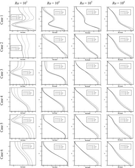
Figure 4 shows the Nusselt number distribution along the hot left wall of the cavity for different positions of the baffle. For the case 1 at Ra = 103, the heat transfer steadily increases by moving from top toward the bottom of cavity, then dramatically decreases due to existence of the baffle and finally reaches to its maximum value close to the bottom of cavity. As far as the effect of the volume fraction of the nanoparticles, the local Nusselt number increases with increase in φ. The effect of volume fraction of nanoparticles on enhancement of heat transfer is more at the upper half of the hot wall. As the Rayleigh number increases the local change in the local Nusselt number due to existence of the baffle diminishes. The thermal conductivity and viscosity of the nanofluid increase with increase in
φ. The increasing thermal conductivity enhance the
heat transfer, while the increasing viscosity diminishes the natural convection. At Ra = 104 the buoyancy force is not strong and contribution of conduction and convection on heat transfer process are comparable. Therefore at this Rayleigh number at the lower half of the hot wall that existence of the baffle motivates to decrease in the flow strength, effect of increasing viscosity of nanofluid is more than increasing thermal conductivity, hence the net effect is decreasing in the heat transfer with increase φ. At Ra = 105 in the part of wall that is located near the baffle, the increase in volume fraction of nanoparticles does not affect the Nusselt number distribution significantly, while at the other
parts of the wall the heat transfer increases with increase in φ. At Ra = 106 by moving from the top of wall, where the temperature gradient is quite low, toward the bottom wall, where the temperature gradient is the highest, the local Nusselt number increases steadily from its minimum value to its maximum value. As the nanofluid is raised along the hot wall, becomes warmer and the temperature gradient decreases and finally the local heat transfer decreases. As can be seen from the figure at this Rayleigh number the rate of heat transfer increases with increase in volume fraction of nanoparticles. It is evident that the effect of increasing φ on enhancement of local heat transfer diminishes by moving from bottom toward the top of the hot wall.
For the case 2 at all considered Rayleigh numbers, by moving from top to the bottom of cavity the local Nusselt number increases steadily. Moreover at all Rayleigh numbers with the exception of Ra = 104 the increase in φ motivates the local heat transfer to decrease. At Ra = 104 in the part of wall that is located under the baffle, the local heat transfer decreases with increasing φ. Moreover at Ra = 103 and 104 by moving from down to the top of the hot wall, effect of volume fraction of nanoparticles on enhancement of heat transfer increases, while at Ra = 105 and 106 a reverse behavior is found.
For case 3 at Ra = 103 the minimum Nusselt number happens at the middle of hot wall, where the baffle is located opposite it. Moreover, as the figure shows, the local Nusselt number increases steadily by moving toward the top and bottom walls. The maximum local Nusselt number occurs at the intersection of left and bottom wall where the temperature gradient is the highest. At higher Rayleigh numbers the rate of local heat transfer increases by moving from top towards the bottom of the hot wall. At Ra = 103 the local Nusselt number increases with increase in φ along all portion of the hot wall, while at Ra = 104 the increase in local Nusselt number with φ is observed only in the part of hot wall that is located over the baffle. At Ra = 105 and 106 by moving from down to the top of the hot wall, effect of volume fraction of nanoparticles on enhancement of heat transfer increases.
9 M. Mahmoodi / JHMTR 1 (2016) 1-13
Ra = 10
3Ra = 10
4Ra = 10
5Ra = 10
6Case 1
Case 2
Case 3
Case 4
Case 5
Case 6
Figure 4. Nusselt number distribution along the hot left wall of cavity with volume fraction of nanoparticles for different cases and at various Rayleigh numbers
Nu local
Y
0.6 0.8 1 1.2 1.4 0 0.2 0.4 0.6 0.8 1 Nu local Y
0.5 1 1.5 2 2.5 3 3.5 4 0 0.2 0.4 0.6 0.8 1 Nu local Y
0 2 4 6 8 10 0 0.2 0.4 0.6 0.8 1 Nu local Y
0 5 10 15 20 0 0.2 0.4 0.6 0.8 1 Nu local Y
0.6 0.8 1 1.2 1.4 0 0.2 0.4 0.6 0.8 1 Nu local Y
0.5 1 1.5 2 2.5 3 0 0.2 0.4 0.6 0.8 1 Nu local Y
2 4 6 8 10
0 0.2 0.4 0.6 0.8 1 Nu local Y
5 10 15 20 0 0.2 0.4 0.6 0.8 1 Nu local Y
0.4 0.6 0.8 1 1.2 1.4 1.6 1.8 2 0 0.2 0.4 0.6 0.8 1 Nu local Y
0 0.5 1 1.5 2 2.5 3 3.5 0 0.2 0.4 0.6 0.8 1 Nu local Y
0 2 4 6 8 10
0 0.2 0.4 0.6 0.8 1 Nu local Y
5 10 15 20 0 0.2 0.4 0.6 0.8 1 Nu local Y
0.6 0.8 1 1.2 1.4 1.6 1.8 2 0 0.2 0.4 0.6 0.8 1 Nu local Y
0.5 1 1.5 2 2.5 3 3.5 4 4.5 0 0.2 0.4 0.6 0.8 1 Nu local Y
2 4 6 8 10
0 0.2 0.4 0.6 0.8 1 Nu local Y
5 10 15 20 0 0.2 0.4 0.6 0.8 1 Nu local Y
0.4 0.6 0.8 1 1.2 1.4 1.6 0 0.2 0.4 0.6 0.8 1 Nu local Y
0 0.5 1 1.5 2 2.5 3 3.5 4 0 0.2 0.4 0.6 0.8 1 Nu local Y
0 2 4 6 8 10
0 0.2 0.4 0.6 0.8 1 Nu local Y
0 5 10 15 20 0 0.2 0.4 0.6 0.8 1 Nu local Y
0.5 1 1.5
0 0.2 0.4 0.6 0.8 1 Nu local Y
0.5 1 1.5 2 2.5 3 3.5 0 0.2 0.4 0.6 0.8 1 Nu local Y
2 4 6 8 10
0 0.2 0.4 0.6 0.8 1 Nu local Y
10 M. Mahmoodi / JHMTR 1 (2016) 1-13
For case 5, existence of the baffle in the upper half of the cavity near the hot wall blocks the nanofluid flow. As can be seen from the Nusselt number distribution, At Ra = 103 the heat transfer decreases in the upper half of the hot wall via existence of the baffle. At higher Rayleigh numbers that the major amount of nanofluid flows into the gap between the baffle and the hot wall existence of the baffle has a minor effect on Nusselt number distribution. At Ra = 104 the increasing φ does not affect local Nusselt number significantly. At Ra = 105 in the part of hot wall which is located near the baffle, the heat transfer decreases with increase in volume fraction of nanoparticles. At Ra = 106 the increase in volume fraction of nanoparticles enhances the rate of heat transfer.
For case 6 similar to case 4, the existence of the baffle does not affect the rate of heat transfer and Nusselt number distribution significantly. At all Rayleigh numbers with the exception of Ra = 104 the increasing Rayleigh number enhances the rate of heat transfer. At Ra = 104 in lower half of the hot wall the local Nusselt number decreases with increase in φ.
Variations of average Nusselt number with volume fraction of nanoparticles for different locations of the baffle are shown in Fig. 5. As can be seen from the figure for all considered cases with the exception of case 1, the average Nusselt number increases with increase in φ. At Ra = 103 for cases 1 and 2 (the baffle located in the lower half of the cavity) and for cases 5 and 6 (the baffle located in the upper half of the cavity), when the volume fraction of nanoparticles is kept constant, same average Nusselt number is observed, while different average Nusselt numbers are found for cases 3 and 4 (the baffle located in the middle of the cavity). Moreover at Ra = 103 the maximum rate of heat transfer occurs for the case 4. For case 4 the baffle which is located in the core of cavity has a minimum effect on blockage of nanofluid flow, hence maximum rate of heat transfer is obtained.
At Ra = 104 minimum effect of volume fraction of nanoparticles on average Nusselt number is observed for case 3. Also at this Rayleigh number the minimum rate of heat transfer occurs for case 3 while its maximum occurs for case 4 that the baffle is located in the core of the cavity. Moreover it is evident from the figure that when the body is located in lower half of cavity (cases 1 and 2) the rate of heat transfer is lower than that when the baffle is located in upper half of cavity (cases 5 and 6). As it was observed earlier from Nusselt number
distributions in Fig. 10, in lower half of the hot wall the rate of heat transfer is higher than that in upper half of the hot wall, hence the existence of the baffle in lower half of cavity blocks the nanofluid flow which motivates higher reduction in heat transfer rate. Furthermore it is observed from the figure that at Ra = 104, for a constant height of location of the baffle when the baffle is located in the middle of cavity the rate of heat transfer is higher than that when the baffle is located near the hot wall.
At Ra = 105 the minimum and maximum mean Nusselt numbers occur for case 1 and case 4, respectively. At this Rayleigh number similar to Ra = 104 when the baffle is kept at a fixed height, the rate of heat transfer for the baffle located in the middle of cavity is higher than that for the baffle located near the hot wall.
At Ra = 106 a different behavior in comparison with lower Rayleigh numbers is observed. As illustrated in the figure at this Rayleigh number the minimum rate of heat transfer occurs for cases 1 and 2, while a similar average Nusselt number is observed for all other cases. As it can be observed from the figure at this Rayleigh number, position of the baffle at the middle of cavity or near the hot wall does not affect the average Nusselt number significantly. It was observed earlier from the streamlines that at Ra = 106 major amount of nanofluids flow at the vicinity of hot wall and effect of position of the baffle decreases. As a result it can be said that at Ra = 106 when the baffle is located higher than the horizontal centerline of cavity, the rate of heat transfer does not change significantly.
11
M. Mahmoodi / JHMTR 1 (2016) 1-13
Ra = 1
03
Ra = 1
04
Ra = 1
0
5
Ra = 1
0
6
Figure 5. Average Nusselt number versus volume fraction of nanoparticles for different cases at various Rayleigh numbers
12 M. Mahmoodi / JHMTR 1 (2016) 1-13
5.
Conclusion
Natural convection fluid flow and heat transfer of Cu-water nanofluid in a square cavity with a baffle were studied numerically using the finite volume method. The left and right wall of the cavity were kept at temperatures of Th and Tc, that Th>Tc, while the horizontal walls were kept insulated. An adiabatic square baffle with six different positions was positioned in the cavity. The numerical procedure was validated by comparing the obtained results with those available in the literature for the free convection in a square cavity filled with air or nanofluid. Subsequently, the code was employed to investigate the effects of Rayleigh number, volume fraction of nanoparticles, and position of the baffle on the heat transfer characteristics and fluid flow within the cavity.
At Ra = 103 when the baffle is located in the lower half of the cavity and when the baffle is located in the upper half of the cavity, same average Nusselt number is obtained for the baffle located at the middle of cavity or near the hot wall. Moreover at Ra = 103 maximum rate of heat transfer occurs for the cavity with a baffle located in the core of cavity.
At Ra = 104 minimum and maximum rate of heat transfer occur for case 3 and case 4, respectively. When the baffle is located in lower half of cavity (cases 1 and 2) the rate of heat transfer is smaller than that when the baffle is located in upper half of cavity (cases 5 and 6).
At Ra = 105 the minimum and maximum mean Nusselt numbers occur for case 1 and case 4, respectively.
At Ra = 104 and 105, when the baffle is kept in a fixed height, the rate of heat transfer for the baffle located in the middle of cavity is higher than when it is located near the hot wall.
At Ra = 106 the minimum rate of heat transfer occurs for cases 1 and 2, while a similar average Nusselt number is observed for all other cases. At this Rayleigh number, the position of the baffle in the middle of cavity or near the hot wall does not affect the average Nusselt number significantly.
References
[1] Santra, A.K., Sen, S., Chakraborty, N., Study of heat transfer due to laminar flow of copper– water nanofluid through two isothermally heated parallel plates, Int. J. Thermal Sci., 48 (2009) 391–400.
[2] Das, S.K., Putra, N., Roetzel, W., Pool boiling characterization of nano-fluids, Int. J. Heat Mass Tranf., 46 (2003) 851-862.
[3] Akbarinia A., Behzadmehr, A., Numerical study of laminar mixed convection of a nanofluid in horizontal curved tubes, Appl. Thermal Eng., 27 (2007) 1327–1337.
[4] Akbari M., Behzadmehr A., Shahraki, F., Fully developed mixed convection in horizontal and inclined tubes with uniform heat flux using nanofluid, Int. J. Heat Fluid Flow, 29 (2008) 545–556.
[5] Arefmanesh, A., Mahmoodi, M., Effects of uncertainties of viscosity models for Al2O3
-water nanofluid on mixed convection numerical simulations, Int. J. Thermal Sci., 50 (2011) 1706-1719.
[6] Mazrouei Sebdani, S., Mahmoodi, M., Hashemi, S.M., Effect of nanofluid variable properties on mixed convection in a square cavity, Int. J. Thermal Sci., In Press.
[7] Khanafer, K., Vafai K., Lightstone M., Buoyancy-driven heat transfer enhancement in a two-dimensional enclosure utilizing nanofluid, Int. J. Heat Mass Tran., 46 (2003) 3639-3653.
[8] Oztop H.F., Abu-Nada E., Numerical study of natural convection in partially heated rectangular enclosures filled with nanofluids. Int. J. Heat Fluid Flow 29 (2008) 1326–1336. [9] Abu-nada, E., Oztop H., Effect of inclination
angle on natural convection in enclosures filled with Cu-Water nanofluid, Int. J. Heat Fluid Flow, 30 (2009) 669–678.
[10]Aminossadati, S.M., Ghasemi, B., Natural convection cooling of a localized heat source at the bottom of a nanofluid-filled enclosure. Eur. J. Mech. B/Fluids, 28 (2009) 630–640. [11]Ögüt, E.B., Natural convection of Water-based
nanofluids in an inclined enclosure with a heat source, Int. J. Thermal Sci., 48 (2009) 2063– 2073.
[12]Lin K.C., Violi A., Natural convection heat transfer of nanofluids in a vertical cavity: Effects of non-uniform particle diameter and temperature on thermal conductivity, Int. J. Heat Fluid Flow, 31 (2010) 236-245.
[13]Sheikhzadeh G.A., Arefmanesh A., Kheirkhah M.H., Abdollahi R., Natural convection of Cu-water nanofluid in a cavity with partially active side walls, Eur. J. Mech. B/Fluids, 30 (2011) 166-176.
[14]Saleh H., Roslan R., Hashim I., Natural convection heat transfer in a nanofluid-filled trapezoidal enclosure, Int. J. Heat Mass Trans., 54 (2011) 194–201.
[15]Sheikhzadeh G.A., Arefmanesh A., Mahmoodi M., Numerical Study of Natural Convection in a Differentially-Heated Rectangular Cavity Filled with TiO2-Water Nanofluid, J. Nano Res., 13 (2011) 75-80.
13 M. Mahmoodi / JHMTR 1 (2016) 1-13
[17]Mahmoodi, M, Numerical simulation of free convection of a nanofluid in L-shaped cavities, Int. J. Thermal Sci., 50 (2011) 1731-1740. [18]Asan, H., Natural convection in an annulus
between two isothermal concentric square ducts, Int. Comm. Heat Mass Trans., 27 (2000) 367-376.
[19]Mezrhab, A., Bouali, H., Amaoui, H., Bouzidi, M., Computation of combined natural-convection and radiation heat-transfer in a cavity having a square body at its center, Appl. Energy,83 (2006) 1004–1023.
[20]Tasnim, S.H, Collins, M.R., Suppressing natural convection in a differentially heated square cavity with an arc shaped baffle, Int. Comm. Heat Mass Trans., 32 (2005) 94–106. [21]Altac, Z., zen Kurtul, Ö, Natural convection in
tilted rectangular enclosures with a vertically situated hot plate inside, Appl. Thermal Eng., 27 (2007) 1832–1840.
[22]Ben-Nakhi, A., Chamkha, A.J., Conjugate natural convection in a square enclosure with inclined thin fin of arbitrary length, Int. J. Thermal Sci., 46 (2007) 467–478.
[23]Kasayapanand, N., A computational fluid dynamics modeling of natural convection in finned enclosure under electric field, Appl. Thermal Eng., 29 (2009) 131–141.
[24]Xu, X, Yu, Z., Hu, Y., Fan, L., Cen, K., A numerical study of laminar natural convective heat transfer around a horizontal cylinder inside a concentric air-filled triangular enclosure, Int. J. Heat Mass Trans., 53 (2010) 345–355.
[25]Chen, W.R., Natural convection heat transfer between inner sphere and outer vertically eccentric cylinder, Int. J. Heat Mass Trans., 53 (2010) 5147–5155.
[26]Abu-Nada, E., Masoud, Z., Hijazi, A., Natural convection heat transfer enhancement in horizontal concentric annuli using nanofluids, Int. Comm. Heat Mass Trans., 35 (2008) 657– 665.
[27]Abouali, O., Falahatpisheh, A., Numerical investigation of natural convection of Al2O3
nanofluid in vertical annuli, Heat Mass Trans., 46 (2009) 15–23.
[28]Abu-Nada, E., Effects of variable viscosity and thermal conductivity of Al2O3–water nanofluid
on heat transfer enhancement in natural convection, Int. J. Heat Fluid Flow, 30 (2009) 679–690.
[29]Mahmoudi, A.H., Shahi, M., Shahedin, A.M., Hemati, N., Numerical modeling of natural convection in an open cavity with two vertical thin heat sources subjected to a nanofluid, Int. Comm. Heat Mass Trans., 38 (2011) 110–118. [30]Mahmoudi, A.H., Shahi, M., Honarbakhsh
Raouf, A., Ghasemian, A., Numerical study of natural convection cooling of horizontal heat source mounted in a square cavity filled with nanofluid, Int. Comm. Heat Mass Trans., 37 (2010) 1135–1141.
[31]Abbasian, A.A., Mahmoodi, M, Amini, M, Free convection in a nanofluid filled square cavity with an horizontal heated plate, Def. Diff. Forum, 312-315 (2011) 433-438. [32]Mahmoodi, M., Numerical simulation of free
convection of nanofluid in a square cavity with an inside heater, Int. J. Thermal Sci., 50 (2011) 2161-2175.
[33]M. Mahmoodi a, Saeed Mazrouei Sebdani, Natural convection in a square cavity containing a nanofluid and an adiabatic square block at the center, Superlatt. Microstruc., 52 (2012) 261–275
[34]Chung, T.J., Computational fluid dynamic, Cambridge University Press, United Kingdom, 2002.
[35]Hoffman, J.D., Numerical Methods for Engineers and Scientists, second ed. Markel Dekker Inc, New York, 2001.
[36]Barakos, G., Mitsoulis, E., Natural convection flow in a square cavity revisited: laminar and turbulent models with wall fraction, Int. J. Numer. Methods Fluids,18 (1994) 695-719. [37]Davis, G.V., Natural convection of air in a
square cavity, a benchmark numerical solution, Int. J. Numer. Methods Fluids, 3 (1983) 249-264.
[38]Fusegi, T., Hyun, J.M., Kawahara, K., Farouk, B., A numerical study of three-dimensional natural convection in a differentially heated cubical enclosure, Int. J. Heat Mass Transfer, 34 (1991) 1543-1557.
[39]Markatos, N.C., Pericleous, K.A., Laminar and turbulent natural convection an enclosed cavity, Int. J. Heat Mass Transfer, 27 (1984) 772-775.