Iranian Journal of Electrical & Electronic Engineering, Vol. 11, No. 1, March 2015 25
The Optimal Steering Control System using Imperialist
Competitive Algorithm on Vehicles with Steer-by-Wire System
F. Hunaini*(C.A.), I. Robandi** and N. Sutantra***
Abstract: Steer-by-wire is the electrical steering systems on vehicles that are expected with the development of an optimal control system can improve the dynamic performance of the vehicle. This paper aims to optimize the control systems, namely Fuzzy Logic Control (FLC) and the Proportional, Integral and Derivative (PID) control on the vehicle steering system using Imperialist Competitive Algorithm (ICA). The control systems are built in a cascade, FLC to suppress errors in the lateral motion and the PID control to minimize the error in the yaw motion of the vehicle. FLC is built has two inputs (error and delta error) and single output. Each input and output consists of three Membership Function (MF) in the form of a triangular for language term "zero" and two trapezoidal for language term "negative" and "positive". In order to work optimally, each MF optimized using ICA to get the position and width of the most appropriate. Likewise, in the PID control, the constant at each Proportional, Integral and Derivative control also optimized using ICA, so there are six parameters of the control system are simultaneously optimized by ICA. Simulations performed on vehicle models with 10 Degree Of Freedom (DOF), the plant input using the variables of steering that expressed in the desired trajectory, and the plant outputs are lateral and yaw motion. The simulation results showed that the FLC-PID control system optimized by using ICA can maintain the movement of vehicle according to the desired trajectory with lower error and higher speed limits than optimized with Particle Swarm Optimization (PSO).
Keywords: Fuzzy Logic Control, Imperialist Competitive Algorithm, Steering Control.
1 Introduction1
In the longitudinal direction of movement of the vehicle should be arranged to always be right in the path specified, if not on the trajectory, it means there a mistake in the direction of the lateral motion. To maintain or minimize the error, it would require a control on the lateral motion [1, 2]. Likewise when movement the vehicle is turning, it will tend to occur the longitudinal force difference between the right and left wheels resulting in a vehicle will experience the yaw motion which pinned on the Centre of Gravity (COG), to reduce the error of the yaw motion then the vehicle requires the yaw motion control [3]. On the condition of vehicle is moving in the longitudinal
Iranian Journal of Electrical & Electronic Engineering, 2015. Paper first received 6 Nov. 2014 and in revised form 9 Dec. 2014. * The Author is with the Electrical Engineering Dept., Widyagama University, Malang, Indonesia.
** The Author is with the Electrical Engineering Dept., Sepuluh Nopember Institute of Technolgy, Surabaya, Indonesia.
*** The Author is with the Mechanical Engineering Dept., Sepuluh Nopember Institute of Technolgy, Surabaya, Indonesia.
E-mails: [email protected], [email protected] and [email protected].
direction and then veer, so the movement of vehicle dynamics can be represented as lateral and yaw motion [4].
The Computing technology has a lot to provide soft computing to perform control functions and optimization. Currently, the vehicle steering control system based on behaviors become the main alternative to the use of the steering control system [5]. Some Artificial Intelligence (AI) techniques have been widely applied to the control and optimization systems. Fuzzy Logic including a technique that is widely applied to vehicle steering control [6–9], but to get the parameters that are required by a Fuzzy Logic Control (FLC) is not an easy job. Soft computing offers a combination and integration of more than one technique Artificial Intellegence aiming to tune the fuzzy parameters automatically, among others, Fuzzy adaptive [8], Genetic Fuzzy [6] and Fuzzy-Particle Swarm Optimization [9].
In 1995 has developed an optimization method based on swarm intelligence, called behavioral inspired algorithm as an alternative of genetic algorithm [10]. In its application, Particle Swarm Optimization (PSO)
becomes an optimization method that simpler and has the ability to achieve a faster convergence than Genetic Algorithm (GA), because this method works only depends on the function of speed and position [11].
On the other side, in 2007 introduced the evolutionary algorithm inspired by imperialistic competition, subsequently it was called the Imperialist Competitive Algorithm (ICA). The ICA applications in the optimization of a mathematical function can provide the results of the optimization process better than using PSO and GA methods [12–14], as well a combination of the fuzzy controller optimized by the ICA has better performance than the expert controller [15].
In this paper was developed an AI-based control system that applied to the model fully automatic steer-by-wire system that represented on the vehicle model with 10 Degree Of Freedom (DOF) [9, 16]. DOF are the vector movement of the vehicle dynamics that describes the state of the physical dynamics of vehicle, where the 10 DOF is meant is, 10 mathematical equations of Newtonian force equation for the longitudinal, lateral, yawing, pitching, rolling, bouncing and the vertical movement of each wheel. The strategy of control system that was developed, consisting of two stages of control, in cascade, namely, the first is FLC as a major control on the lateral motion and the second is Proportional-Integral-Derivative controller (PID) as an advanced control on the yaw motion. To obtain the parameters of the optimal control system on the FLC and PID used an optimization method of ICA. The expected results of this simulation on active steering control with the use of FLC and PID control tuned by ICA can improve vehicle dynamic performance.
2 Vehicle Dynamics Model
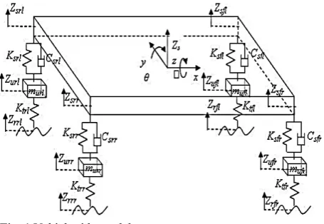
Based on the theory of vehicle dynamics, vehicle has two major functions in controlling the movement of vehicles, namely control lateral and control longitudinal [17], but to further represent the whole movement of the vehicle either vertical or horizontal direction, the models built in this paper uses a vehicle model with a 10-DOF that consists of a 7-DOF vehicle ride model,
Fig. 1, and 3-DOF vehicle handling model, Fig. 2. Vehicle ride models expressed in 7 of mathematical equations [16], consists of forces equations on the vehicle body (sprung mass single) that includes freedom of movement; vertical movement of the vehicle body (heaving), nodding movement of the vehicle body (pitching), the movement of swaying from side to side of the vehicle body (rolling) and the vertical movement of each wheel (four unsprung masses) [16, 18, 19].
Bouncing of the car body (Zs) is represented as:
2 , , 2 , ,
2 , , 2 , , ,
, , , , , , , ,
, , ,
(1)
The Pitching of the car body (θ) is:
2 , , 2 , ,
2 , , 2 , ,
, , , , , ,
, , , , , ,
(2)
Rolling of the car body (ϕ) is expressed as:
0.5 , , 0.5 , ,
0.5 , , 0.5 , , 0.5 , ,
0.5 , , 0.5 , , 0.5 , ,
0.5 , , 0.5 , , 2
2
(3)
Vertical Direction for each wheel is:
, , , , ,
0.5 , 0.5 , , ,
, , ,
(4)
, , , , ,
0.5 , 0.5 , , ,
, , ,
(5)
, , , , ,
0.5 , 0.5 , , ,
– , , ,
(6)
, , , , ,
0.5 , 0.5 , , ,
, , ,
(7)
Vehicle handling models expressed in 3 of mathematical equation [16], consists of forces equations on the movement of the car body, namely the lateral, longitudinal and yaw motion. Lateral motion and longitudinal motion is movement along the x-axis and y-axis are expressed in lateral acceleration (Ay) and
longitudinal acceleration (Ax) so that the lateral motion
and the longitudinal motion can be obtained by double integration of the lateral and longitudinal acceleration [16, 20, 21].
Fig. 1 Vehicle ride model.
Hunaini et al: The Optimal Steering Control System using Imperialist Competitive Algorithm on … 27 Fig. 2 Vehicle handling model.
Lateral and longitudinal acceleration are expressed as follows:
(8)
(9)
An angular movement of the vehicle based on the vertical axis is called a yaw motion ( ) [13] which can be obtained by the integration of rand r.
1
2 2 2 2
(10)
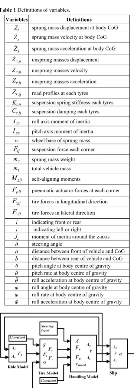
Definitions of variables are shown in Table 1. Based on the tenth of mathematical equation above, namely 7 DOF of the ride models and 3 DOF of handling models that are mathematically linked using Calspan tire models [8, 22, 23] then was built vehicles models using MATLAB-Simulink software as shown in Fig. 3.
The design of the vehicle model with 10 DOF that focuses on setting the direction of the front wheels of the vehicle as the output of a plant and the plant input in the form variations of steer angle (δ) of the steering wheel. Plant output in the form of the front wheels direction of vehicles stated in the three movements, namely lateral motion (y), the longitudinal motion (x) and yaw motion (r). The yaw motion will affect the moment of inertia around the z-axis (Js), changes in roll and pitch angles on COG (θ and φ) [9], so it will affect the whole of force in the z-axis direction (bounching, pitching, rolling and all the vertical direction of each wheel).
Table 1 Definitions of variables.
Variables Definitions
Zs sprung mass displacement at body CoG
s
Z sprung mass velocity at body CoG
s
Z sprung mass acceleration at body CoG
ij u
Z, unsprung masses displacement
ij u
Z, unsprung masses velocity
ij r
Z, unsprung masses acceleration
ij r
Z, road profiles at each tyres
Ks,ij suspension spring stiffness each tyres
ij s
C, suspension damping each tyres
xx
I roll axis moment of inertia
yy
I pitch axis moment of inertia
w wheel base of sprung mass
ij
F suspension force each corner
s
m sprung mass weight
t
m total vehicle mass
zij
M self-aligning moments
pij
F pneumatic actuator forces at each corner
xij
F tire forces in longitudinal direction
yij
F tire forces in lateral direction i indicating front or rear
j indicating left or right
Jz moment of inertia around the z-axis δ steering angle
a distance between front of vehicle and CoG b distance between rear of vehicle and CoG
θ pitch angle at body centre of gravity pitch rate at body centre of gravity roll acceleration at body centre of gravity roll angle at body centre of gravity roll rate at body centre of gravity roll acceleration at body centre of gravity
Fig. 3 Vehicle Model in MATLAB-SIMULINK.
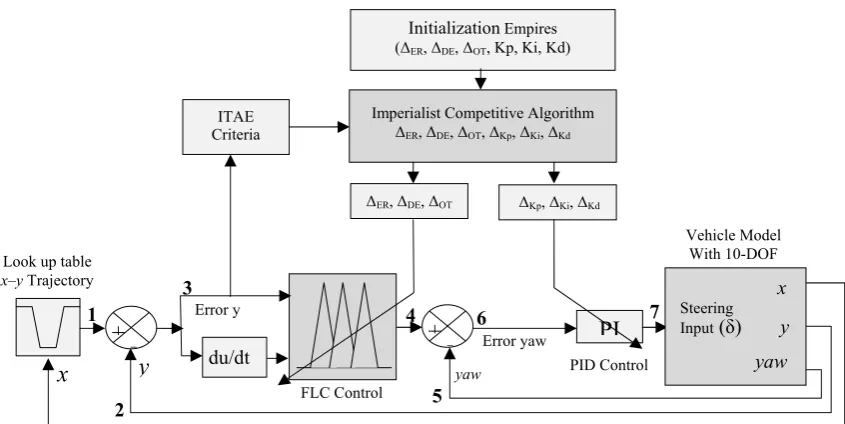
Fig. 4 The Control and Optimization Structure for automatic steering on vehicle model.
3 Optimization of Control Systems
Steering control system (active steer) of the vehicle that was built in this paper uses two controllers in a cascade [16, 24, 25], FLC as the main control and PID control as the auxiliary control. This control strategy is needed to control the direction of the front wheels to fit the desired vehicle trajectory. Block diagram of the control strategy that is built for the active steering control simulation are shown in Fig. 4. The role of control systems are; FLC is used to suppress the error y (3) among; lateral motion y (2) against the desired trajectory (1) corresponding to the longitudinal motion coordinates x, whereas the PID the control is used to reduce errors, speed up risetime, and reduce overshot / undershot among yaw motion (5) against the setting point which is the output of the FLC (4). The ideal condition of fuzzy control results (output FLC) is vehicle movement no longer has a lateral motion y, so that the output FLC will be setting point on PID control to minimize the yaw motion error (6). Both the control systems will work optimally if supported by the design of composition the optimal parameter values, in this paper, the values of the parameter at FLC and PID control is determined through the optimization process by ICA.
3.1 Fuzzy Logic Controller (FLC)
FLC is designed using two inputs, namely error (ER) as the difference of the required values against the actual value, delta error (DE) as the velocity error, and a control output (OT) as a control action. In this way, the control action expected to produce a close loop system which has a response with minimum overshoot and fast rise time.
The main structure of the FLC, consisting of: crisp variables fuzzification, fuzzy rules and defuzzyfication [26]. Fuzzification of crisp variable is the conversion
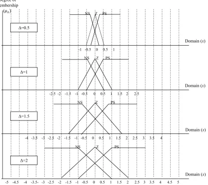
value of the input and output of the control system into a fuzzy variable by using the technique of membership function (MF). MF is a function to express the membership degree of fuzzy. Because of FLC functioned only to suppress the error lateral motion which vary linearly around the zero, then the mapping of the fuzzy input to the membership degree of fuzzy is described as a straight line consisting of two states, namely linear-up and linear-down. In the linear-up, increase in fuzzy set began in domain value that have degree of membership of zero (0) moves up to the right side toward the domain value that have higher degree of membership up to 1, while the linear-down, straight line began from the highest degree of membership (1) on the left side move downwards to the domain value that have a lower degree of membership until 0. Triangle membership of function is a curve which is basically a combination of the two straight lines, while the trapezium curve is essentially such as a triangular shape, it's just that there are a few points that have membership of value are 1. Therefore, in the MF that used in this paper are a MF in the form of a triangle (Triangular shape) and trapezium (trapezoidal shape).
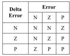
Fuzzy rules are a set of rules that are grouped into the rule base for decision making (the inference process) of the required control action. Each rule base on the control input (error and delta error) and the control output of the FLC consists of three MF with language term, negative (N), Zero (Z), Positive (P). Thus the number of the required rule base is 9 rules, and having regard to the response curve of the plant, it can be arranged into rule base with the following rationale:
- If ER="P" and DE="Z", then it is necessary to a positive control action, OT="P" in order to the response immediately to the set-point.
ΔER, ΔDE, ΔOT
Imperialist Competitive Algorithm
ΔER, ΔDE, ΔOT, ΔKp, ΔKi, ΔKd
PI
+ -
du/dt+
x
Steering
Input (δ) y
yaw
x
y
yawLook up table
x–y Trajectory
Error y
Error yaw ITAE
Criteria
FLC Control
PID Control
Initialization Empires (ΔER, ΔDE, ΔOT, Kp, Ki, Kd)
ΔKp, ΔKi, ΔKd
Vehicle Model With 10-DOF
1
2
3
4
5
6 7
Hunaini et al Table 2 Rule b
- If ER= overshoot tha negative con
- And so the other cur as shown in T
The shap may change on the varia called (Δi). T
a function of then paramet in the positio in Figs. 5 and
Fig. 5 Parame
Fig. 6 Parame
l: The Optima base of Fuzzy L
Delta Error
N
Z
P
="Z" and DE at occurs to a ntrol action, OT
on to the poin rve cutoff poin
Table 2. pe of triangula
based on the ables of mult This means tha f Δ, so that wh ter every MF on of (Cn) and
d 6.
ters of triangula
ters of trapezoi
al Steering Co Logic Controlle
Error
N Z P
N N Z
N Z P
Z P P
E="N", then minimum, it T="N". nt of maximum nt, so the rule
ar and trapezo e width and m tiplier, then t at all paramete hen the value will change in d width (Wn)
ar membership
dal.
ontrol System u er.
P
Z
P
P
in order to is necessary t
m, minimum es can be deri
oidal of each midpoint depe
the multiplier ers of each M
of Δ be chan nvolves a cha of MF as sho
function. using Imperia the to a and ived MF ends r is F is nged ange own as mu the wid 6 a are Cn W W WR WL pos mi val so cha cha det of tha usi fuz me the tun PID err Pro res use the the con con con Kp the com usi out mo yaw by oth pop alist Competiti Multiplier va the multiplier ultiplier for M e multiplier fo dth and midpo and as the follo Changes of e:
1 Cn ∆
Changes of t
W WR
R WR
L WL
The C, WR sition, the w dpoint of MF lue and "n+1"
that each MF ange in positi ange of value The value of termined by tr the multiplier at is repeatedl
ing ICA. Defuzzyficat zzy variable ethods that use
PID control e simplicity o ning the cont
D control use ror between
oportional con sponse of the ed to minimiz e system and e overshot / ntrols is highl nstant value o ntrol optimize p, Ki and Kd t e parameters o mposition of ing ICA. Setti
tput of FLC, oved without l
w motion is eq
3.3. Imperi ICA is a new imperialistic her optimizati pulation called
ive Algorithm alue Δi (ΔER,
r for MF of in MF of input on or MF of FLC
oint on each M owing equatio the trapezoid the trapezoida ∆ WL ∆ ∆ R, and WL, r width of the r F, whereas s " is the new v F parameter w ion C and the of Δ as shown f the multiplie rial and error, r is obtained ly until an op
tion is a proc on the crisp ed is the centr
3.2 PID C is a popular of its structur trol parameter ed as a secon the set poi ntrol (P) used system (rise ze or eliminat Derivative C undershot. P ly dependent o of Kp, Ki and ed by determi through the le of Kp, Ki and the optimal v ing point used
this means lateral forces, qual to zero.
ialist Compet w optimizatio competition a ion methods, d the initial em
on …
ΔDE, ΔOT) con
nput of the err n the delta erro
C output. Det MF is express on:
dal and triang
al and triangul (for trapezoid (for triangula
respectively e right and left subscript "n" value after the will be change e width W of
n in Fig. 7. er ΔER, ΔDE, an
but in this pa through a lea ptimal value i
cess to change variable, De roid.
Control control system re, as well as rs [27]. In th nd control to int of the y d to accelerat
time), Integr te the steady-Control (D) us Performance
on the determ d Kd. In this p
ining the cons earning proce d Kd up to be values of all d on the PID
that the vehi , or in other w
titive Algorith on strategy th among the em ICA starts w mpire.
29 nsists of; ΔER
or; ΔDE as the
or; and ΔOT as
ermination of sed in Figs. 5,
gular position
(11) ar wide are: dal MF) (12) ar MF) (13) (14) (15) expressed the ft side of the is the initial change of Δ, ed include the f the MF. The
nd ΔOT can be
aper, the value arning process is reached by
e back all the efuzzyfication
m because of s the ease of his paper, the eliminate the yaw motion. te the rate of ral control (I) -state error of sed to reduce P, I, and D mination of the paper the PID stant value of ss, or by tune e achieved the constants by control is the icle has been words that the
hm (ICA) hat is inspired mpire, Such on with an initial
R e s f , n e e l , e e e e s y e n f f e e . f ) f e D e D f e e y e n e d n l
Fig. 7 Change the width and center of the membership function.
Each individual of an empire is a country. There are two kinds of countries; namely the countries of the colony and the imperialist countries that collectively forming an empire. During the competition, a weak empire will collapse and the stronger will be the ruler of the colony. Imperialistic competition will reach convergent if there is only one empire and its colonies are in the same position and have the same cost as the imperialist [12, 13].
In search of the optimal value, the optimization steps using ICA are as follows:
Step 1. Creation of Initial Empires.
Parameters that will be optimized are 6 parameters, consists of three parameters required by FLC (ΔER,
ΔDE, and ΔOT) and three parameters required by PID control (Kp, Ki and Kd). Optimization preceded by generating the initial population a number of 50 countries, then determined the 8 countries as the initial empires and the remaining are called colonies were distributed proportionally in each empire.
Then the initial countries evaluated at the plant of active steering control system for sorting out the cost, in ascending order, in this paper the cost stated in the error of lateral motion which is measured using the minimizing of Time-weighted Integral Absolute Error (ITAE) criterion [27] as follows:
| | (16) e(t) is the error as a function of time between the reference against the actual of lateral motion. The total error is the total cost of colonies on each imperialist who will be the strength of every empire where the less the cost is, the more is the power.
Step 2. Moving the colonies towards the relevant imperialist.
In the first decade, all colonies assimilation and revolution against imperialist. The direction of movement from the colony towards imperialist is a vector, expressed as a random variable x with a uniform distribution:
~ 0, (17)
~ , (18)
-2.5 -2 -1.5 -1 -0.5 0 0.5 1 1.5 2 2.5 -1 -0.5 0 0.5 1
-4 -3.5 -3 -2.5 -2 -1.5 -1 -0.5 0 0.5 1 1.5 2 2.5 3 3.5 4
-5 -4.5 -4 -3.5- -3 -2.5 -2 -1.5 -1 -0.5 0 0.5 1 1.5 2 2.5 3 3.5 4 4.5 5
Degree of membership
(
Domain (x) Domain (x) Domain (x) Domain (x)
NS Z PS
NS Z PS
NS Z PS
NS Z PS
Δ=2 Δ=1.5
Δ=1 Δ=0.5
Hunaini et al: The Optimal Steering Control System using Imperialist Competitive Algorithm on … 31 is a value greater than 1, causing the colony
approached to imperialist and d is the distance vector between the colony into imperialist. θ indicates a new direction with the change angle γ that can be determined randomly. In this paper, β and γ are determined respectively 3 and 0.5.
Step 3. The exchange of imperialist position with a closest colony.
When the colony moving closer into imperialists, the colony may reach a position with the smallest cost. In this situation, there will be an exchange position, the imperialists will be move to the position of closest colony and conversely, then this algorithm will be repeated with the conditions on the new imperialist position, colony started again to move closer into imperialists. At this stage, the position of each colony will be evaluated again on plant of active steering control system to get a new cost by using ITAE.
Step 4. Calculating the total cost of all empires.
(19)
The ξ used in this paper is 0.02. Step 5. Imperialistic Competition.
Determine the total power (Normalized total cost ) from the each empire.
(20)
Empire which have less power will be eliminated in imperialist competition and their colonies will be divided into the several other empire.
Step 6. Termination of iterations.
Iteration will be stopped when only staying one empire, but when it was still more than one empire, the process is repeated back to step 2.
4 Simulation Results and Discussion
Simulation of optimal control on the lateral and yaw motion in the steering system of the vehicle begins with optimize the parameters of FLC and PID control system using ICA, then the simulation results compared against the use of PSO optimization method as has been done on previous paper [16]. This comparison is done in order to get smaller errors that will be used as a basis for advanced research involving the hardware on the vehicle steering system, called Hardware In the Loop Simulation (HILS). Testing the steering control system by HILS aims to obtain more accurate result and real.
The parameters used in the ICA: Number of initial countries = 50; Number of Initial Imperialists = 8; Number of Decades = 50; Revolution Rate = 0.3; Assimilation coefficient = 3; Assimilation angle coefficient = 0.5;
Zeta = 0.02;
Damp Ratio = 0.99;
Uniting Threshold = 0.02;
The parameters used in the PSO: Number of particles = 50; Maximum iteration = 50; social constant (c1) = 1;
cognitive constant (c2) = 1;
Inertia value (W) = 0.5; Learning rates (L1,2) = 0.5;
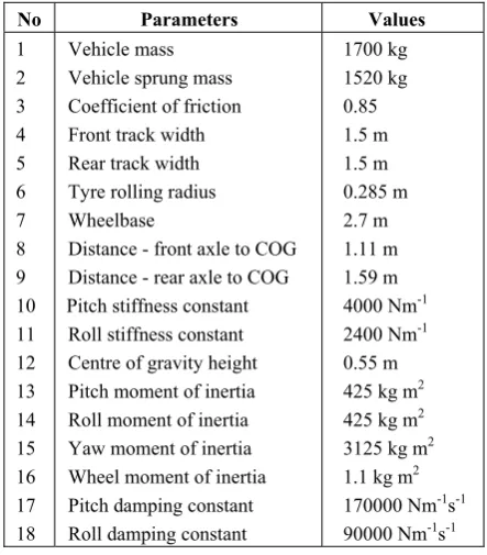
The parameters of the vehicle model are used as shown in Table 3.
Optimizations that has been done using ICA can achieve convergence on 19th iterations while the optimization using PSO can achieve convergence only up to the third iteration as shown in Fig. 8.
Table 3 Parameters of Vehicle models.
No Parameters Values
1 2 3 4 5 6 7 8 9 10 11 12 13 14 15 16 17 18
Vehicle mass Vehicle sprung mass Coefficient of friction Front track width Rear track width Tyre rolling radius Wheelbase
Distance - front axle to COG Distance - rear axle to COG Pitch stiffness constant
Roll stiffness constant Centre of gravity height Pitch moment of inertia Roll moment of inertia Yaw moment of inertia Wheel moment of inertia Pitch damping constant Roll damping constant
1700 kg 1520 kg 0.85 1.5 m 1.5 m 0.285 m 2.7 m 1.11 m 1.59 m 4000 Nm-1
2400 Nm-1
0.55 m 425 kg m2
425 kg m2
3125 kg m2
1.1 kg m2
170000 Nm-1s-1
90000 Nm-1s-1
Fig. 8 Convergence of ICA and PSO Optimization.
0 10 20 30 40 50
0 1 2 3 4 5 6x 10
-49
Iteration
Fi
tn
e
ss Func
ti
on /
C
o
st
s
I C A PSO
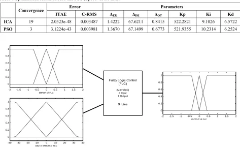
Table 4 Optimization results of ICA and PSO (Speed=13.88 m/s).
Convergence Error Parameters
ITAE C-RMS ΔER ΔDE ΔOT Kp Ki Kd
ICA 19 2.0523e-48 0.003487 1.4222 67.6211 0.8415 522.2821 9.1026 6.5722
PSO 3 3.1224e-43 0.003981 1.3670 67.1499 0.6773 521.9355 10.2314 6.2524
Fig. 9 The optimal shape of the MF in the FLC.
The optimization done either using ICA or PSO is an iterative process until the maximum iteration equals 50, applied to both FLC and PID control system of the model vehicle with steering input in the form of a table of x-y trajectory (double lane change) at a constant speed of 13.88 m/s. This means that on control system has been occurred learning that begins with a random parameter values and in the end can determine the values of the optimal parameters with the error restrictions of the smallest lateral motion. The size of the error is used in the optimization process is ITAE, while the size of the error is used on the simulation model is Continues Root Mean Square Error (C-RMS error) as shown in Table 4.
The error value obtained from the optimization using ICA is smaller than using PSO, but on optimization using PSO achieve faster convergence than the ICA, this further strengthens the assertion that the PSO is a method that premature in achieving convergence [11].
The value of ΔER, ΔDE, and ΔOT obtained is a
multiplier factor to determine the width and position of each of the MF and the value of Kp, Ki and Kd is the expression value for the parameter Proportional, Integral and Derivative. The optimal shape of the MF can be seen in Fig. 9 and the optimal value of the width and the midpoint of the MF, shown in Table 5.
The results of optimization of vehicle steering control system is expressed in Fig. 10 where shows that the movement of the vehicle with the optimal control
system can adjust well on the desired trajectory (double lane change trajectory).
Table 5 The width and midpoint of the MF yang optimal.
ERROR INPUT
ΔER=1.4222 Width Left Midpoint Width Right
NS -0.7111 -0.7111 0
Z -0.7111 0 0.7111
PS 0 0.7111 0.7111
DELTA ERROR INPUT
ΔDE=67.6211 Width Left Midpoint Width Right
NS -33.81055 -33.81055 0
Z -33.81055 0 33.81055
PS 0 33.81055 33.81055
OUTPUT
ΔOT=0.7617 Width Left Midpoint Width Right
NS -0.38085 -0.38085 0
Z -0.38085 0 0.8415
PS 0 0.38085 0.38085
-2 -1.5 -1 -0.5 0 0.5 1 1.5 2 0
0.2 0.4 0.6 0.8 1
ERROR of FLC
-40 -30 -20 -10 0 10 20 30 40 0
0.2 0.4 0.6 0.8 1
DELTA ERROR of FLC
-2 -1.5 -1 -0.5 0 0.5 1 1.5 2 0
0.2 0.4 0.6 0.8 1
OUTPUT of FLC
Fuzzy Logic Control (FLC)
(Mamdani) 2 Input 1 Output
9 rules
Hunaini et al: The Optimal Steering Control System using Imperialist Competitive Algorithm on … 33 Fig. 10 The Lateral motion and the desired trajectory (Double
Lane Change).
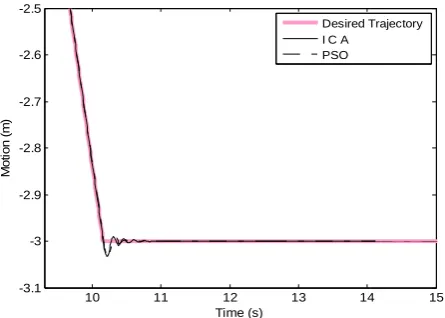
Fig. 11 The first maneuver of double lane change trajectory.
Fig. 12 The second maneuver of double lane change trajectory.
Figs. 11 and 12 show two of the four responses of the optimal control system against the desired trajectory during vehicle maneuvers, in Fig. 11 occurs when the vehicle is moving in the x direction and then veering
towards y hence happened overshot to the x direction. Otherwise on Fig. 12, the vehicle is moving in the y direction and then veering towards x hence happened overshot on the y direction and in Fig. 13 are characteristics of the optimal control system include; Lateral motion error, output FLC (setting point of the yaw motion), the output of the yaw motion control, yaw motion error and the output of the vehicle steering control system.
The results of the optimal control system simulation using ICA (FLC-PID tuned by ICA) is expressed in the form of C-RMS error compared with the results of the optimal control system simulation using a PSO (FLC-PID tuned by PSO) both for double lane change trajectory (trajectory with sharp maneuver) or sinewave trajectory (trajectory with smooth maneuvers), as shown in Table 6. The overall average value of C-RMS error on testing using the FLC-PID tuned by ICA is smaller than the test FLC-PID tuned by PSO.
Fig. 13 The characteristics of optimal control system.
Table 6 Benchmark of Control Systems.
0 5 10 15 20 25 30
-3.5 -3 -2.5 -2 -1.5 -1 -0.5 0 0.5
Time (s)
M
o
ti
on (m
)
Desired Trajectory I C A
PSO
6 6.5 7 7.5 8 8.5 9
-0.5 -0.4 -0.3 -0.2 -0.1 0 0.1
Time (s)
M
o
ti
on (
m
)
Desired Trajectory I C A
PSO
10 11 12 13 14 15
-3.1 -3 -2.9 -2.8 -2.7 -2.6 -2.5
Time (s)
M
o
ti
on
(m
)
Desired Trajectory I C A
PSO
0 5 10 15 20 25 30
-3 -2 -1 0
Time (s)
Characteristic Respon System
Desired Trajectory Output System by ICA
0 5 10 15 20 25 30
-0.05 0 0.05
Time (s)
Error Lateral Motion
0 5 10 15 20 25 30
-0.5 0 0.5
Time (s)
Output FLC (Set Point Yaw)
0 5 10 15 20 25 30
-0.1 0 0.1
Time (s)
M
ot
ion
(m
)
Output Yaw Motion
0 5 10 15 20 25 30
-0.5 0 0.5
Time (s)
0 5 10 15 20 25 30
-2 0 2x 10
4
Time (s)
Output PID Control (Output Control System) Error Yaw Motion
No
Velocity C-RMS Error Double Lane Change
C-RMS Error Sinewave Trajectory
Km /h
m/s
FLC– PID
tuned by
ICA
FLC–PID
tuned by
PSO
FLC–PID
tuned by
ICA
FLC–PID
tuned by
PSO 1 10 2.77 0.043310 0.055950 0.011390 0.014400 2 20 5.55 0.010390 0.012580 0.004681 0.005677 3 30 8.33 0.005456 0.006690 0.002949 0.003574 4 40 11.11 0.004043 0.004799 0.002175 0.002619 5 50 13.89 0.003487 0.003981 0.001744 0.002082 6 60 16.67 0.002720 0.003458 0.001609 0.001760 7 70 19.45 time out time out 0.002833 0.001605 8 80 22.22 time out time out 0.007159 time out
5 Conclusion
Strategy of Optimal control system developed on the vehicle steering system is to always keep the movement of vehicle stay on the desired trajectory. At the time the vehicle was speeding or maneuvering, the vehicle should not experience a lateral force then be used of Fuzzy Logic Control to suppress the error of lateral motion, and to enhance the movement of vehicles spared from yawing movement then be used PID control to minimize the error of yaw motion. In order for both control system work optimally then the first required parameters optimized using ICA, namely the position and width of the MF on the input and output of the FLC as well as the constants of gain of the PID control.
The results of optimization obtain the optimal parameter values at the time of achieved convergence with value ITAE 2.0523e-48. Optimal parameters that have been obtained embedded in the control system then performed simulations the vehicle steering control system. The simulation results can be stated that the optimal control system that has been built (FLC-PID tuned by ICA) for controlling a vehicle steering system always be able to maintain the movement of the vehicle to the desired trajectory either of the double lane change or sine wave trajectory with the lower error and higher speed limits Compared by optimal control system that tuned using PSO (FLC-PID tuned by PSO).
Acknowledgements
This research was funded by grants of Research of Competitive Grant, for it is pronounced thanks profusely to DP2M Directorate General of Higher Education Ministry of National Education of Indonesia and all those who have helped up to this research can be completed.
References
[1] R. T. O’Brien, P. A. Iglesias and T. J. Urban, “Vehicle lateral control for automated highway systems”, IEEE Trans. Control Syst. Technol., Vol. 4, No. 3, pp. 266-273, May 1996.
[2] F. Hunaini, I. Robandi and N. Sutantra, “Model and Simulation of Vehicle Lateral Stability Control”, the 2nd APTECS, 2010, International Seminar on Applied Technology, Science, and Arts, Surabaya, ITS, p. 26, 2010.
[3] V. Cerone, M. Milanese and D. Regruto, “Yaw Stability Control Design Through a Mixed-Sensitivity Approach”, IEEE Trans. Control Syst. Technol., Vol. 17, No. 5, pp. 1096-1104, Sep. 2009.
[4] J. Villagra, B. d’ Andrea-Novel, H. Mounier and M. Pengov, “Flatness-Based Vehicle Steering Control Strategy With SDRE Feedback Gains Tuned Via a Sensitivity Approach”, IEEE Trans. Control Syst. Technol., Vol. 15, No. 3, pp. 554-565, May 2007.
[5] S. H. M. Amin and A. Adriansyah, “Particle Swarm Fuzzy Controller for Behavior-based Mobile Robot”, The 9th International Conference on Control, Automation, Robotics and Vision, 2006. ICARCV ’06, Singapore, pp. 1-6, 2006. [6] L. Cai, A. B. Rad and W.-L. Chan, “A Genetic
Fuzzy Controller for Vehicle Automatic Steering Control”, IEEE Trans. Veh. Tech., Vol. 56, No. 2, pp. 529-543, Mar. 2007.
[7] K. R. S. Kodagoda, W. S. Wijesoma and E. K. Teoh, “Fuzzy speed and steering control of an AGV”, IEEE Trans. Control Syst. Tech., Vol. 10, No. 1, pp. 112-120, Jan. 2002.
[8] E. P. Ping, K. Hudha and H. Jamaluddin, “Hardware-in-the-loop simulation of automatic steering control for lanekeeping manoeuvre: outer-loop and inner-loop control design,” Int. J. Veh. Safety, Vol. 5, No. 1, pp. 35-59, 2010.
[9] F. Hunaini, I. Robandi and N. Sutantra, “Modeling and Simulation of Vehicle Stability Control on Steer by Wire System Using Fuzzy Logic Control and PID Control Tuned by PSO”, The 3rd International Conference on Engineering and ICT (ICEI2012), Melaka, Malaysia, p. 85, 2012.
[10] J. Kennedy and R. Eberhart, “Particle swarm optimization”, IEEE International Conference on Neural Networks, Vol. 4, pp. 1942-1948, 1995. [11] A. Adriansyah and S. H. M. Amin, “Learning of
fuzzy-behaviours using Particle Swarm Optimisation in behaviour-based mobile robot”, Int. J. Intell. Syst. Tech. Appl., Vol. 5, No. 1/2, pp. 49-67, May 2008.
[12] E. Atashpaz-Gargari and C. Lucas, “Imperialist competitive algorithm: An algorithm for optimization inspired by imperialistic competition”, IEEE Congress on Evolutionary Computation, CEC 2007, pp. 4661-4667, 2007. [13] E. Atashpaz Gargari and F. Hashemzadeh,
“Colonial competitive algorithm: A novel approach for PID controller design in MIMO distillation column process”, Int. J. Intell. Comput. Cybern., Vol. 1, No. 3, pp. 337-355, 2008.
[14] M. H. F. Zarandi, M. Zarinbal, N. Ghanbari and I. B. Turksen, “A new fuzzy functions model tuned by hybridizing imperialist competitive algorithm and simulated annealing. Application: Stock price prediction”, Information Sciences, Vol. 222, pp. 213–228, Feb. 2013.
[15] A. Mohammadzadeh Jasour and E. Atashpaz Gargari, “Vehicle Fuzzy Controller Design Using Imperialist Competitive Algorithm”, Second First Iran. Jt. Congr. Fuzzy Intell. Syst. Tehran Iran, 2008.
[16] F. Hunaini, I. Robandi and N. Sutantra, “Optimization of automatic steering control on vehicle with steer by wire system using particle
Hunaini et al: The Optimal Steering Control System using Imperialist Competitive Algorithm on … 35 swarm optimization”, Turk. J. Electr. Eng.
Comput. Sci., pp. 1–35, Dec. 2013.
[17] P. Falcone, F. Borrelli, J. Asgari, H. E. Tseng and D. Hrovat, “Predictive Active Steering Control for Autonomous Vehicle Systems”, IEEE Trans. Control Syst. Technol., Vol. 15, No. 3, pp. 566-580, May 2007.
[18] K. Hudha, Z. A. Kadir, M. R. Said and H. Jamaluddin, “Modelling, validation and roll moment rejection control of pneumatically actuated active roll control for improving vehicle lateral dynamics performance”, Int. J. Eng. Syst. Model. Simul., Vol. 1, No. 2/3, p. 122, 2009. [19] F. Ahmad, K. Hudha and H. Jamaluddin, “Gain
Scheduling PID Control with Pitch Moment Rejection for Reducing Vehicle Dive and Squat”, Int. J. Veh. Safety, Vol. 4, No. 1, pp. 1–30, 2009. [20] P. Falcone, F. Borrelli, J. Asgari, H. E. Tseng and
D. Hrovat, “Predictive Active Steering Control for Autonomous Vehicle Systems”, IEEE Trans. Control Syst. Technol., Vol. 15, No. 3, pp. 566-580, May 2007.
[21] M. R. Stone and M. A. Demetriou, “Modeling and simulation of vehicle ride and handling performance”, The Proceedings of the 2000 IEEE International Symposium on Intelligent Control, Rio Patras, pp. 85-90, 2000.
[22] K. Hudha, Z. A. Kadir, M. R. Said and H. Jamaluddin, “Modelling, validation and roll moment rejection control of pneumatically actuated active roll control for improving vehicle lateral dynamics performance”, Int. J. Eng. Syst. Model. Simul., Vol. 1, No. 2/3, p. 122, 2009. [23] F. B. Ahmad, K. Hudha and H. Jamaluddin,
“Gain Scheduling PID Control with Pitch Moment Rejection for Reducing Vehicle Dive and Squat”, Int. J. Veh. Safety, Vol. 4, No. 1, pp. 45-83, 2009.
[24] F. Hunaini, I. Robandi and N. Sutantra, “Vehicle Stability Control On Steer By Wire System Using Fuzzy Logic”, ICAST,2011, The International Student Conference on Advanced Science and Technology, Shandong University, Jinan, China, pp. 3-42-p., 2011.
[25] Z. A. Obaid, N. Sulaiman, M. H. Marhaban and M. N. Hamidon, “Analysis and Performance Evaluation of PD-like Fuzzy Logic Controller Design Based on Matlab and FPGA”, IAENG Int. J. Comput. Sci., Vol. 37, No. 2, pp. 146-156, 2010.
[26] F. Xiuwei, F. Li and K. Feng, “Research of Automotive Steer-by-Wire Control Based on Integral Partition PID Control”, in 3rd International Conference on Genetic and Evolutionary Computing, 2009. WGEC’09, Guilin, China, pp. 561-564, 2009.
[27] F. G. Martins, “Tuning PID Controllers using the ITAE Criterion”, Int. J. Engng Ed., Vol. 21, No. 5, pp. 867-873, 2005.
Fachrudin Hunaini received the B.Sc. degree in Electrical Engineering from the University of Widyagama, Malang, Indonesia, in 1991 and M, Eng., degree in Electrical Engineering from Sepuluh Nopember Institute of Technolgy, Surabaya, Indonesia in 1999. At this time as a candidate Dr.Eng. in Electrical Engineering at Sepuluh Nopember Institute of Technolgy, Surabaya, Indonesia. The current research focused on optimal control system - based on behavior on the steering of vehicles using Steer-by-wire system.
Imam Robandi recived B.Sc. degree in power engineering from Sepuluh Nopember Institute of Technolgy, Surabaya, Indonesia in 1989, and M, Eng., degree in Electrical Enginering from the Bandung Institute of Technology, Indonesia in 1994 and Dr.Eng. degree in the Department of Electrical Engineering from Tottori University, Japan, 2002. He is currently Professor and as Chairman of the Laboratory of Power System Operation and Control in the Department of Electrical Engineering, Sepuluh Nopember Institute of Technology, Surabaya, Indonesia. His current reasearch interest includes Stability of power systems, Electric Car, Solar cell and Artificial Iintelegent Control.
Nyoman Sutantra He recived B.Sc. degree in the Department of Mechanical Engineering of Sepuluh Nopember Institute of Technolgy, Surabaya, Indonesia in 1976, a Master of Science (M.Sc.) at the University of Wisconsin, USA in 1980, and Doctor of Philosofy (Ph.D) in the universities that the same in 1984, with the area of expertise "Vehicle Dynamics and Stability". He is currently Professor and as chairman of the Mechanical Engineering Laboratory of Automotive Sepuluh Nopember Institute of Technology (ITS) Surabaya, Indonesia. Various research in the automotive field along with the researchers and students of master's and doctoral programs have been carried out. Together with the research group and a doctoral student and the master has made a research vehicle called the "Smart Car".