Forces Affecting Timber Skidding (p.127-139)
13
0
0
Full text
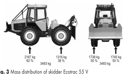
(2) @. Toma{i} et al.. Fig. 1 Distribution of forces during uphill timber skidding Slika 1. Raspodjela sila pri privla~enju skiderom uz nagib through horizontal winch rollers (Hassan and Gustafson 1983). The value of tractive force depends on the adhesive weight of the skidder and hence for obtaining higher tractive force higher adhesive weight is necessary (Sever 1984). Therefore, in timber skidding, the heavier end of timber assortments in the load should be lifted off the ground so as to increase the adhesive weight by higher value of vertical component of rope force. The distribution of loads by skidder axles changes with respect to the load volume and weight, orientation of assortments in the load, travel direction and terrain slope. During travel on longitudinal slope, the rear axle is additionally loaded as the load of the skidder weight is transferred from the front axle due to the effect of the parallel weight component of the skidder (G sina). During uphill timber skidding, the tractive force must overcome the traction resistance of the part of load dragged on the soil (H), as well as the resistance of the horizontal weight component of the skidder (G sina) that pulls the vehicle downhill (Fig. 1). During downhill travel, under the effect of the horizontal weight component of the skidder (G sina), the load of the skidder weight is transferred to the front axle (Fig. 2). In the same way, the horizontal weight component of the skidder acts in the skidder’s travel direction and hence it is only necessary. Fig. 2 Distribution of forces during downhill timber skidding Slika 2. Raspodjela sila pri privla~enju skiderom niz nagib 128. Forces Affecting Timber Skidding (127–139). to overcome the traction resistance of the part of load dragged on the soil (H). Based on the above considerations, the highest load is expected at the skidder’s rear axle during uphill skidding. Due to different wheel loads, transmission must enable the distribution of the torque with respect to the wheel load. Consequently with the mechanical transmission system, the distribution of the torque to the wheels should be in accordance with the wheel load distribution. The research of torque on skidder’s wheel shafts (Horvat 1987, [u{njar and Horvat 2006, Maren~e 2005) confirmed the hypothesis that higher torque is applied on the wheel under higher load, where torques at the wheels of the same shaft are balanced. The aim of this paper is to determine the dependence of components of rope force, wheel load distribution and torque on load weight and terrain slope, which represents a significant correlation for the assessment of tractive (exploitation) characteristics of skidders in timber skidding.. 2. Materials and methods – Materijali i metode In this research, the skidder ECOTRAC 55 V equipped with forest winch Hittner 2 ´ 35 kN (Fig. 3) was used. The skidder mass is 3483 kg (62% at the front axle and 38% at the rear axle). The skidder’s driving engine is a 3-cylinder DEUTZ diesel engine, air cooled, displacement 3236 cm3, compression ratio 20:1, power output 40 kW at 2300 min–1 and highest torque of 207 Nm at 1600 min–1. The transfer of power is carried out by mechanical transmission: drive engine ® clutch ® gear box ® drive distribution ® front and rear differentials with individual blockade ® final (planetary) drive in tractor wheels. For measuring the dynamic load of the skidder, measuring parameters were designed or applied for simultaneous determination of components of rope force, load and torque on all driving wheels.. Fig. 3 Mass distribution of skidder Ecotrac 55 V Slika 3. Raspored mase skidera Ecotrac 55 V Croat. j. for. eng. 30(2009)2.
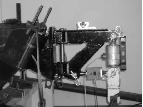
(3) Forces Affecting Timber Skidding (127–139). Tensometry is the basic method for measuring mechanical values. Heidl and Husnjak (1992) describe tensometry as a mechanical method for determining length deformation of a structure or model in order to determine the strain on the structure surface. In doing so, measurement transducers are used based on changeable electrical resistance caused by the change of its legth (the so-called »strain gauge«). This method provides the possibility to measure electrically non-electric values. The application of tensometric method enables the measurement without affecting adversely the vehicle structure, but it requires the conversion of vehicle elements into measurement parameters. Tensometric method was used by Sever (1987), Marklund (1987), Horvat (1998), Maren~e (2005) and [u{njar and Horvat (2006), Toma{i} et al. (2008) for measuring wheel torques and wheel load of skidders and forwarders. Horizontal and vertical component of rope force in timber skidding was determined with two transducers HBM 50 kN and HBM 20 kN. Transducers were connected under the angle of 90 degrees and installed on the support structure articulately mounted on vertical rollers of the winch (Fig. 4). Transducers were placed horizontally and vertically with respect to the basis at fully lifted skidder’s rear protective and anchoring blade, corresponding to its position in timber skidding. The measurement of torques was carried out by strain gauges placed opposite the housing of the final planetary drives. For measuring dynamic wheel load, the strain gauges were placed right behind the wheels on the upper part of the shaft housing leading from the differential to the wheel. Strain gauges were connected by conductors to the juncture. Due to wheel rotation it was necessary to install a sliding. Fig. 4 Carrier with traction and tension transducers Slika 4. Nosa~ s vla~no-tla~nim dinamometrima Croat. j. for. eng. 30(2009)2. @. Toma{i} et al.. Fig. 5 Preparation of final (planetary) drive Slika 5. Prepariranje planetarnoga reduktora transducer on each wheel. The carriers of the sliding transducers were installed on the housing of the final drive (Fig. 5). The signal of the strain gauge resistance change is transmitted through the sliding transducer by cables to the amplifier. All measuring transducers and strain gauges are connected to measuring amplifiers HBM Spider 8 installed on the skidder. The use of the radio modem ELPRO 805 U (ELPRO Technologies Pty Ltd.) enabled remote transmission of data. The radio modem was installed on the skidder and connected to the measuring amplifier HBM Spider 8. It received analogically amplified measurement signals and transmitted them through the antenna installed on the roof of the skidder cabin. Another radio modem received the measurement signals and transmitted them into the field computer. The software programme Catman 4.0 (Hottinger Baldwin Messtechnik GmbH) was used for making records of the measurement data at the frequency of 50 Hz. Measurement tranducers were recorded into the software programme by channels and measuring constants obtained by calibration of measurement transducers were then entered. Further data processing of the measuring results was carried out by the software programme Microsoft Excell. During traction tests, changes were measured of wheel load of unloaded skidder on plane ground. In case of reduction of wheel load, the result of measurement will be deducted from the wheel load of the unloaded skidder, i.e. it will be added in case of increase of wheel load. Due to the described way of measurement, it was necessary to establish the mass and wheel load of the unloaded skidder. Although these data are provided by the manufacturer, by installing the measuring equipment, carriers and aux-. 129.
(4) @. Toma{i} et al.. iliary structures and devices, the basic skidder mass and wheel load increased. The mass and wheel load of an unloaded skidder were determined by four scales by a Sweden manufactured TELUB connected to a measuring amplifier HBM Spider 8, which is directly connected to a laptop so that the measuring results were read by a computer programme Catman 4.0. The measurement showed that the mass of the equipped skidder was 3647 kg, i.e. that the mass was increased by 164 kg compared to the basic mass. The front wheels were additionally loaded, 36 kg by each wheel. Rear wheels have a slightly higher load (45 kg and 47 kg), which is caused by installation of traction and tension transducers for measuring the vertical and horizontal rope force at the rear end. Traction and tension transducers are installed on the carrier connected to the carrier connected to roller bases of the winch on the skidder rear protective and anchoring blade, and since higher loads are possible, the structure of the transducer carrier is massive. Load distribution to wheels remained almost unchanged compared to the distribution of values measured by manufacturers. The skidder front axle, equipped with the measuring devices, is loaded with 61% of the total skidder weight, and the rear axle with 39%, while the load ratio of the front/rear axle of the skidder as delivered by the manufacturer is 62%:38%. The load distribution to wheels with respect to the left and right side of the skidder is 50%:50%.. 3. Research results – Rezultati istra`ivanja The research was carried out on the strip road where longitudinal slopes were determined by the leveling method as well as individual distances of the strip road of uniform slope. Longitudinal slopes increase with the distance from the beginning of the strip road. The lowest route slope was recorded at the beginning of the strip road (2.3%), and then followed the road sections with higher longitudinal slope: 15%, 18.3%, 27.0% and 35.5%. The highest slope of the strip road was selected based on the investigation of limit slopes for skidder movement. MacDonald (1999) recorded the highest limit slope for skidders of 35% downhill, and Inoue and Tsuji (2003) the slope of 45% downhill and 30% uphill. 8 beech logs with the mean diameters ranging between 27 cm and 39 cm were used for the research. Based on the measured dimensions, log volumes were calculated. Log volumes ranged between 0.32 m3 and 0.50 m3. The mass of individual logs was weighed. 130. Forces Affecting Timber Skidding (127–139). by two scales TELUB connected to the measuring amplifier HBM Spider 8 and laptop. Based on the known volume and mass of logs, the characteristics were determined of the load to be used in traction tests. 9 types of load were selected, with 1 to 4 pieces in a load, of the size between 0.27 and 1.8 m3 and weight ranging between 2.49 kN and 17.38 kN. Skidders were used for carrying out traction tests in downhill and uphill skidding of different loads. The traction test consisted of skidding of a certain load from the starting point at the beginning of the strip road through parts of the strip road with increasing longitudinal slopes until the end of the strip road. If not all terrain slopes could be overcome due to too large load, the traction test would be interrupted at the slope level that could be overcome. Downhill skidding started from the highest slope. Out of 9 uphill traction tests, i.e. skidding of 9 types of load, the skidder reached the top of the slope in six tests. In skidding the three largest loads, successful traction tests were made on the first two uphill slopes. The same occurred with downhill tractive tests: the skidding of three largest loads was only recorded for the two lowest slopes. At the final tractive tests, the wheel load was measured in uphill and downhill unloaded skidder travel. All measuring results were expressed as mean values per traction test with individual load and the determined longitudinal slope of strip road. Table 1 shows the measuring results of the vertical and horizontal components of rope force in timber skidding by the skidder Ecotrac 55V according to strip road slope, skidding direction and load size. In uphill skidding, the values of the vertical component of rope forces are higher than the horizontal component on all longitudinal slopes up to 18.3% for all skidded loads. On longitudinal slopes ranging between 27.0% and 35.5% the horizontal component is higher than the vertical for load weights of 7.83 kN and 9.55 kN. With smaller loads, the vertical component of rope forces remained higher than the horizontal one. These results show that the increase of slope results in decrease of part of load pulled by the rope, i.e. the part of load dragged on the soil is increased. Therefore, higher horizontal force component is required for overcoming the traction resistance of the part of load dragged on the soil. In downhill skidding, the vertical component of rope forces in each traction test is higher than the horizontal component. The increase of downhill slope results in the decrease of values of both components of rope forces, and the described phenomenon is more conspicuous with the horizontal component. Croat. j. for. eng. 30(2009)2.
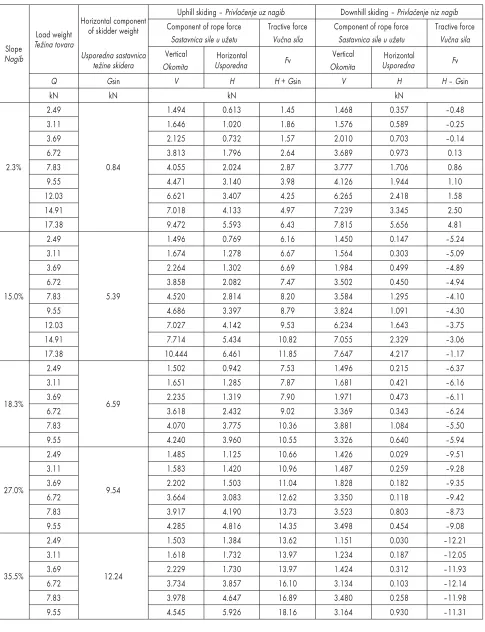
(5) Forces Affecting Timber Skidding (127–139). @. Toma{i} et al.. Table 1 Components of rope force and tractive forces Tablica 1. Sastavnice sile u u`etu i vu~ne sile. Slope Nagib. 2.3%. 15.0%. 18.3%. 27.0%. 35.5%. Horizontal component of skidder weight Load weight Te`ina tovara Usporedna sastavnica te`ine skidera Q kN 2.49 3.11 3.69 6.72 7.83 9.55 12.03 14.91 17.38 2.49 3.11 3.69 6.72 7.83 9.55 12.03 14.91 17.38 2.49 3.11 3.69 6.72 7.83 9.55 2.49 3.11 3.69 6.72 7.83 9.55 2.49 3.11 3.69 6.72 7.83 9.55. Gsin kN. 0.84. 5.39. 6.59. 9.54. 12.24. Croat. j. for. eng. 30(2009)2. Uphill skiding – Privla~enje uz nagib Component of rope force Tractive force Sastavnica sile u u`etu Vu~na sila Vertical Horizontal Fv Usporedna Okomita V 1.494 1.646 2.125 3.813 4.055 4.471 6.621 7.018 9.472 1.496 1.674 2.264 3.858 4.520 4.686 7.027 7.714 10.444 1.502 1.651 2.235 3.618 4.070 4.240 1.485 1.583 2.202 3.664 3.917 4.285 1.503 1.618 2.229 3.734 3.978 4.545. H kN 0.613 1.020 0.732 1.796 2.024 3.140 3.407 4.133 5.593 0.769 1.278 1.302 2.082 2.814 3.397 4.142 5.434 6.461 0.942 1.285 1.319 2.432 3.775 3.960 1.125 1.420 1.503 3.083 4.190 4.816 1.384 1.732 1.730 3.857 4.647 5.926. Downhill skiding – Privla~enje niz nagib Component of rope force Tractive force Sastavnica sile u u`etu Vu~na sila Vertical Horizontal Fv Usporedna Okomita. H + Gsin. V. 1.45 1.86 1.57 2.64 2.87 3.98 4.25 4.97 6.43 6.16 6.67 6.69 7.47 8.20 8.79 9.53 10.82 11.85 7.53 7.87 7.90 9.02 10.36 10.55 10.66 10.96 11.04 12.62 13.73 14.35 13.62 13.97 13.97 16.10 16.89 18.16. 1.468 1.576 2.010 3.689 3.777 4.126 6.265 7.239 7.815 1.450 1.564 1.984 3.502 3.584 3.824 6.234 7.055 7.647 1.496 1.681 1.971 3.369 3.881 3.326 1.426 1.487 1.828 3.350 3.523 3.498 1.151 1.234 1.424 3.134 3.480 3.164. H kN 0.357 0.589 0.703 0.973 1.706 1.944 2.418 3.345 5.656 0.147 0.303 0.499 0.450 1.295 1.091 1.643 2.329 4.217 0.215 0.421 0.473 0.343 1.084 0.640 0.029 0.259 0.182 0.118 0.803 0.454 0.030 0.187 0.312 0.103 0.258 0.930. H – Gsin –0.48 –0.25 –0.14 0.13 0.86 1.10 1.58 2.50 4.81 –5.24 –5.09 –4.89 –4.94 –4.10 –4.30 –3.75 –3.06 –1.17 –6.37 –6.16 –6.11 –6.24 –5.50 –5.94 –9.51 –9.28 –9.35 –9.42 –8.73 –9.08 –12.21 –12.05 –11.93 –12.14 –11.98 –11.31. 131.
(6) @. Toma{i} et al.. Forces Affecting Timber Skidding (127–139). The lowest value of the horizontal component of rope forces (0.03 kN) was recorded in downhill skidding with the slope of 27% and 35% of the smallest load of 2.49 kN. In downhill skidding on higher longitudinal slopes, the front end of the load gets closer to the rear end of the skidder, which causes the increase of the vertical component of rope forces that holds the load eleveted off the soil. In doing so, lower horizontal component of forces is required because lower weight of the load is dragged on the soil. It was not possible to tie the loads made of three or four timber assortments to the carrier of the rope tied to transducers exclusively with the heavier end eleveted off the ground. With respect to the position of timber assortments in the load, and the position of the load with resprect to the rear end of the skidder, irregular sequence of values of horizontal component of forces was observed in downhill skidding on the two highest longitudinal slopes. In uphill skidding, the tractive force is used for overcoming the traction resistance of the part of load dragged on the soil (H) and the opposite effect of resistance of horizontal component of skidder weight (G sina) that pulls the skidder downhill, due to the effect of gravitation, in the opposite direction of traction. Table 1 shows the values of this calculation of tractive force. It can be seen from the presented data that the values of horizontal component of skidder weight increase with the increase of the slope of the test skid trail. On lower slopes, the effect of horizontal component of rope forces, used for overcoming the traction resistance, increases, because the hori-. zontal component of the skidder weight has lower values due to small angles. From the slope of 18.3%, the effect of horizontal component of skidder weight on the value of the tractive force is considerably higher than the traction resistance, regardless of the size of the skidded load. In downhill slope, the horizontal component of skidder weight (G sina) acts in the direction of skidder travel, by which traction resistances are overcome more easily. Only on the lowest slope, positive values were recorded of the tractive force, due to low inclination of the skid trail (the value G sina that is deducted from the the horizontal component of the traction resistance is only 0.84 kN). On other skid trail slopes the calculated values of tractive forces were mostly negative. It can be clearly seen from the above data that due to the increase of the load weight (Q), and hence also of the horizontal component of rope forces (H), the negative values of tractive forces are usually decreased, and however compared to the effect of the skidder weight in the traction direction, this effect on the value of the tractive force is incomparably lower. The dependence of the tractive force on the load weight, skidding direction and strip road slope is shown in Fig. 6 and 7. In uphill skidding, the tractive force increases with the increase of the longitudinal slope and load weight. With the increase of the slo-. Fig. 6 Dependance of tractive force on load weight in uphill skidding Slika 6. Ovisnost vu~ne sile o te`ini tereta pri vu~i uz nagib. Fig. 7 Dependance of tractive force on load weight in downhill skidding Slika 7. Ovisnost vu~ne sile o te`ini tereta pri vu~i niz nagib. 132. Croat. j. for. eng. 30(2009)2.
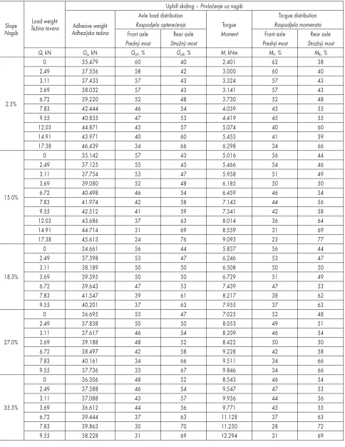
(7) Forces Affecting Timber Skidding (127–139). pe, resistances increase caused by the impact of the part of skidder weight, acting contrary to the traction direction, and the increase of load weight increases the values of the horizontal component of rope forces (traction resistance). The skidder’s tractive force must overcome the values of both resistances in uphill skidding. In downhill skidding, based on low inclination of regression lines, it can be established that horizontal component of the skidder weight has a lower impact on the values of tractive forces, than the impact of traction resistance. In this research, the wheel load was determined from the data of dynamic measurement of changes of wheel loads in traction tests from the previoiusly determined values of statistical weight distribution of unloaded skidder. Tables 2 and 3 show the measured skidder’s adhesive weights and axle load distribution in traction tests. The results of measurement of unloaded skidder travel are presented for the purpose of analysing the impact of load weight and strip road slope on axle load distribution. During uphill travel of unloaded skidder, the front axle load decreases with the increase of longitudinal slope. On the highest slope of 35.5%, the rear axle load of the unloaded skidder is higher due to the effect of horizontal component of skidder weight G·sina, which contributes to the transfer of load weight from the front axle to the rear axle. In traction tests, the rear axle load increases with the increase of load weight and slope. The increase of load weight increases the vertical component of rope forces that carries the part of load eleveted off the ground and additionally increases the load on the rear axle. On the lowest slope, the front axle is under higher load with the 4 smallest loads, on the following slope of 15% with the three smallest loads, on slopes of 18.3% and 27% only with the smallest load. On the highest slope, higher load was recorded on the rear axle in all tracton tests. Sever (1984) states that the longitudinal stability of the skidder is questionable when the load ratio of the front and rear axle reaches the value of 1:3.5 or 22%:78%. According to Weise and Nick (2003) at least 10% of the total dynamic load should remain on the front axle so as to enable steering. The highest load of the rear axle was recorded in skidding the largest load of 17.38 kN on the slope of 15% and it was 76% of the total adhesive weight. Under such conditions, 24% of the total adhesive weight remains on the front axle, which is very close to the limit value when the skidder’s longitudinal stability is compromised. This is why the skidder could not pull the three largest loads on the following slope of the strip road of 18.3%. Higher values of the Croat. j. for. eng. 30(2009)2. @. Toma{i} et al.. vertical force component with these loads along with the effect of the horizontal component of the skidder weight G sina on such longitudinal slope would result in the decrease of the front axle load under the limit value of 22% of the total adhesive weight and in the disruption of the skidder’s longitudinal stability. The analysis of the measuring results of downhill traction tests shows higher load of the front axle with the increase of the slope in skidding the same load, but also higher load of the front axle with the decrease of load weight on the same slope. In all traction tests, including the unloaded skidder, on slopes higher than 18.3% in download skidding, higher load of the skidder’s front axle was recorded. It should be noted that in downhill skidding of the largest loads on lower slopes, the load of the skidder’s rear axle is higher than the load of its front axle, i.e. the load of the front axle decreases with respect to the rear axle. It can be concluded that the horizontal component of the skidder weight (G sina) contributses to the load transfer from the rear axle to the front axle, but overcoms the effect of the vertical component of rope force (V) so that higher load is applied on the rear axle. As already explained, the essence of the effect of the skidder transmission system is the transmission of torque from the engine to the wheel. In doing so, the value of torque changes, starting with the gear box, through drive distributio to the final (planetary) drives in skidder wheels. As the transmission system with skidders is mechanical, the torque is tramsmitted mechanically and during this transmission its value changes with respect to wheel load. Along with wheel load distribution Tables 2 and 3 also show the measured mean values of the skidder axle torque distribution. In uphill skidding, uniform increase can be observed of the total values of torques with the increase of load and slope. When analisying the torques of the front and rear axle, it can be clearly seen that the increase of the load results in considerable increase of rear wheel torques, and in the decrease of front wheel torques, which is in accordance with the above considerations on loads. The skidder could not reach the top of the 3 highest slopes with the largest load, but on the last slope of 18.3% that was overcome, the mean torque of 7.0 kNm was achieved at the rear wheels, which is the highest value achieved up to that slope in all uphill traction tests. After that, the highest value of the skidder’s rear axle torque is achieved in traction tests on higher slopes with the heaviest loads with which the said slopes were overcome. In downhill skidding on testing skid trails, a very interesting situation appears in the analysis of the skidder’s wheel torques in timber skidding. On the. 133.
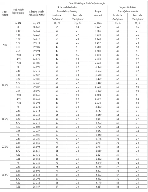
(8) @. Toma{i} et al.. Forces Affecting Timber Skidding (127–139). Table 2 Axle load and torque distribution in uphill skidding Tablica 2. Raspodjela optere}enja i momenata po osovinama pri privla~enju uz nagib. Slope Nagib. 2.3%. 15.0%. 18.3%. 27.0%. 35.5%. 134. Load weight Te`ina tovara. Q, kN 0 2.49 3.11 3.69 6.72 7.83 9.55 12.03 14.91 17.38 0 2.49 3.11 3.69 6.72 7.83 9.55 12.03 14.91 17.38 0 2.49 3.11 3.69 6.72 7.83 9.55 0 2.49 3.11 3.69 6.72 7.83 9.55 0 2.49 3.11 3.69 6.72 7.83 9.55. Adhesive weight Adhezijska te`ina Ga, kN 35.479 37.556 37.433 38.032 39.220 42.444 40.835 44.871 43.971 46.439 35.142 37.125 37.754 39.080 40.498 41.974 42.512 43.686 44.714 45.613 34.661 37.398 38.189 39.395 39.643 41.547 40.201 36.695 37.838 37.617 39.188 38.497 40.161 37.736 36.306 37.588 37.088 36.612 39.444 39.863 38.228. Uphill skiding – Privla~enje uz nagib Axle load distribution Raspodjela optere}enja Torgue Moment Front axle Rear axle Prednji most Stra`nji most GaF, % GaR, % M, kNm 60 40 2.401 58 42 3.000 57 43 3.324 57 43 3.141 52 48 3.730 46 54 4.059 47 53 4.419 43 57 5.074 40 60 5.453 34 66 6.298 57 43 5.016 55 45 5.466 53 47 5.958 52 48 6.185 46 54 6.459 42 58 7.143 41 59 7.341 37 63 8.014 31 69 8.559 24 76 9.093 56 44 5.837 53 47 6.246 50 50 6.508 50 50 6.729 47 53 7.439 39 61 8.217 37 63 7.955 53 47 7.025 50 50 8.053 46 54 8.209 48 52 8.422 42 58 9.228 34 66 9.511 33 67 9.846 48 52 8.543 46 54 9.547 43 57 9.956 44 56 9.771 37 63 11.128 30 70 11.250 31 69 12.294. Torgue distribution Raspodjela momenata Front axle Rear axle Prednji most Stra`nji most MF, % M R, % 62 38 60 40 57 43 57 43 52 48 45 55 45 55 40 60 41 59 34 66 56 44 54 46 51 49 50 50 46 54 44 56 42 58 36 64 31 69 23 77 56 44 53 47 50 50 51 49 47 53 38 62 37 63 52 48 49 51 46 54 50 50 42 58 34 66 34 66 46 54 47 53 44 56 45 55 37 63 28 72 31 69. Croat. j. for. eng. 30(2009)2.
(9) Forces Affecting Timber Skidding (127–139). @. Toma{i} et al.. Table 3 Axle load and torque distribution in downhill skidding Tablica 3. Raspodjela optere}anja i momenata po osovinama pri privla~enju niz nagib. Slope Nagib. 2.3%. 15.0%. 18.3%. 27.0%. 35.5%. Load weight Te`ina tovara. Adhesive weight Adhezijska te`ina. Q, kN 0 2.49 3.11 3.69 6.72 7.83 9.55 12.03 14.91 17.38 0 2.49 3.11 3.69 6.72 7.83 9.55 12.03 14.91 17.38 0 2.49 3.11 3.69 6.72 7.83 9.55 0 2.49 3.11 3.69 6.72 7.83 9.55 0 2.49 3.11 3.69 6.72 7.83 9.55. Croat. j. for. eng. 30(2009)2. Ga, kN 38.040 36.369 36.460 36.616 39.311 39.509 39.294 41.394 44.872 45.100 34.593 37.719 37.537 37.188 37.342 39.287 38.699 42.862 42.463 45.291 35.271 37.314 36.743 37.366 37.318 37.606 37.337 34.989 35.729 35.062 36.694 36.659 37.172 38.068 33.742 35.388 36.698 35.846 36.295 37.343 36.187. Downhill skiding – Privla~enje niz nagib Axle load distribution Raspodjela optere}enja Torgue Moment Front axle Rear axle Prednji most Stra`nji most GaF, % GaR, % M, kNm 66 34 1.967 59 41 1.806 58 42 1.973 60 40 2.140 54 46 2.427 49 51 2.900 49 51 2.608 44 56 3.450 42 58 4.058 37 63 4.963 68 32 –0.893 68 32 –0.604 67 33 –0.518 65 35 –0.429 58 42 –0.442 54 46 0.240 57 43 –0.022 50 50 0.504 48 52 0.959 43 57 2.070 67 33 –1.433 69 31 –1.167 66 34 –1.069 63 37 –1.011 59 41 –1.203 57 43 –0.725 59 41 –1.067 69 31 –3.350 73 27 –3.176 71 29 –2.911 64 36 –2.911 66 34 –3.059 59 41 –2.621 65 35 –2.832 73 27 –4.579 76 24 –4.149 71 29 –4.307 67 33 –4.693 69 31 –4.332 66 34 –4.170 67 33 –4.251. Torgue distribution Raspodjela momenata Front axle Rear axle Prednji most Stra`nji most MF, % MR, % 65 35 59 41 55 45 63 37 52 48 47 53 49 51 45 55 41 59 38 62 66 34 68 32 69 31 67 33 59 41 50 50 50 50 49 51 46 54 42 58 65 35 69 31 64 36 63 37 59 41 54 46 56 44 69 31 73 27 72 28 64 36 68 32 59 41 65 35 76 24 77 23 73 27 67 33 70 30 65 35 68 32. 135.
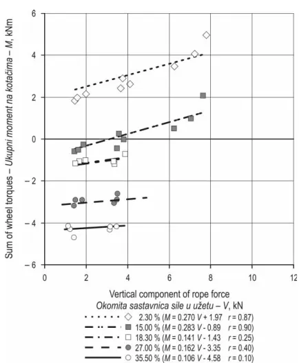
(10) @. Toma{i} et al.. Forces Affecting Timber Skidding (127–139). lowest negative slope, the wheel torque is positive. On the following longitudinal slope of 14.9% in skidding smaller loads, negative torque appeared at the skidder shafts, in very low negative amounts that ranged between –0.2 kNm and –0.9 kNm in unloaded skidder travel. In skidding larger loads, the skidder had to achieve the required combination of tractive forces by positive amounts of total wheel torques of 0.2 kNm and up to 2.1 kNm. On the following slope of 18.3%, in skidding of all types and sizes of loads in unloaded skidder travel, all values of torques were recorded in negative amounts. The negative values of total torques are relatively low and they range between –0.7 kNm in skidding the heaviest load, tested on this slope, and –1.4 kNm achieved durting unloaded skidder travel. We have a similar situation with the last two highest slopes, with the difference that the amounts of the achieved negative wheel torques are considerably higher and they range between –2.6 kNm and –4.7 kNm, which implies that the increase of negative slope results in the increase of the achieved negative amounts of torques. This phenomenon of negative skidder wheel torques in downhill skidding was also recorded by Maren~e (2005) and [u{njar and Horvat (2006). In this case, torques are not used for generating wheel. tractive forces, and instead, the transmission of torque through the transmission system causes skidder’s braking performance. The skidder’s need for braking arises under the influence of the horizontal component of the skidder weight (G sina) that pushes the skidder downhill. Torque distribution to skidder axles shows the same ratios as wheel load distribution. Considering the impact of the vertical component of rope forces (V) on the value of the skidder adhesive weight, the analysis was made of torque dependence right on this value (force). Figures 8 and 9 show the data with regression lines. Points on the ordinate axis represent wheel torques during unloaded skidder travel on testing skid trails. At such values, torques enable overcoming of terrain slope and rolling resistance of an unloaded skidder. In uphill skidding (Fig. 8) it can be observed that the increase of the vertical component of rope forces results in the increase of skidder wheel torque. This can be understood because the vertical component of rope forces directly causes the increase of the skidder adhesive weight, and hence also the rolling resistance, which is consequentially related to the increase of torques that must enable the generation of the circumferential force required for overcoming this increased resistance and other traction resis-. Fig. 8 Dependance of wheel torque on vertical component of rope force and uphill slope Slika 8. Ovisnost zakretnoga momenta na kota~ima o vertikalnoj sastavnici sile u u`etu i nagibu u usponu. Fig. 9 Dependance of wheel torque on vertical component of rope force and downhill slope Slika 9. Ovisnost zakretnoga momenta na kota~ima o vertikalnoj sastavnici sile u u`etu i nagibu u padu. 136. Croat. j. for. eng. 30(2009)2.
(11) Forces Affecting Timber Skidding (127–139). tances. According to the position and equations of regression lines it can also be read from Fig. 8 that the value of slope and load (load size) undoubtedly affect the value of wheel torque. On lower slopes, the lines are more horizontal (direction coefficients of 0.42 and 0.43), which means that the increase of the vertical component of rope forces result in slower increase of torque. On higher slopes this impact is definitey more significant (0.73). It can be concluded from this analysis that the value of wheel load that represent the pulled load affects considerably the increase of the values of required wheel torque. In downhill skidding, it can be observed in Fig. 9 according to the heights of regression lines that here the values of parallel skidder weight forces have a prevailing impact on the value of the skidder wheel torques. This is confirmed by low values of the correlation coefficient of regression lines. However, the impact of the vertical component of rope forces can be seen in the increase of the rolling resistance, by which the skidder’s downhill travel is slowed, and hence less braking is necessary as well as lower torque. Thus, it can be concluded from the survey of achieved torques in downhill travel that the negative values of wheel torques were decreased in skidding larger loads at the highest slopes.. 4. Conclusions – Zaklju~ci The determination of dependence of components of rope forces, skidder load and wheel torques on load weight and terrain slope represents a significant relationship for the possibility of assessing skidder traction characteristics in timber skidding. Torque distribution depends on the skidder wheel vertical load. In uphill skidding, torques increase proportionally to the vertical component of rope forces and adhesive weight of the skidder. According to the results of research, the following conclusions can be made related to the effect of forces with respect to the required tractive force in uphill skidding: by the increase of longitudinal slope, more tractive force is used for overcoming the terrain slope than for overcoming the traction resistance. In downhill skidding, the horizontal component of the skidder weight (G sina) acts in the skidder travel direction and hence its value is higher than the traction resistance. In the same way, with downhill skidding, the skidder wheel torques are negative, because they are not used for achieving wheel tractive force and instead, the transmission of torque through the transmission system causes skidder’s braking performance. The skidder’s need for braking arises under influence of the horizontal component of the skidder Croat. j. for. eng. 30(2009)2. @. Toma{i} et al.. weight (G sina) that acts in the direction of the skidder travel and under its effect the traction resistances are overcome. Further to the above said, it can be concluded that in case of downhill skidding we cannot speak of achieving real tractive force because the skidder pulls the load only by its weight, and the transmittion from engine to wheels is not used for achieving the tractive force.. 5. References – Literatura Hassan, A. E., Gustafson, M. L., 1983: Factors Affecting Tree Skidding Forces, Transactions of the ASAE, 26(1): 47–53. Heidl, I., Husnjak, M., 1992: Tenzometrija. Tehni~ka enciklopedija, Leksikografski zavod »Miroslav Krle`a«, Svezak 12: 685–690. Horvat, D., 1987: Skidder Wheel Torque Measuring. Proceedengs of 9th ISTVS International Conference, Barcelona, Vol. II: 531–541. Inoue, M., Tsujii, T., 2003: Management, technology and system design of mechanized forestry in Japan. Textbook of forestry mechanization technology, Forestry Mechanization Society, Tokyo, Japan, Forestry Machine Series No: 92, 1–122. MacDonald, A. J., 1999: Harvesting Systems and Equipment in British Columbia. FERIC, Handbook No. HB-12: 1–197. Maren~e, J., 2005: Spreminjanje tehni~nih parametrov traktorja pri vla~enju lesa – kriterij pri izbiri delovnega sredstva. Disertacija, Biotehni{ka fakulteta Univerze u Ljubljani, Slovenija: 1–271. Marklund, B. O., 1987: Torque distribution on wheeled vehicles affects damage on the forest ground. Proceedings of 9th ISTVS International Conference, Barcelona, Vol. 1: 347–354. Sever, S., 1984: Istra`ivanje nekih eksploatacijskih parametara traktora kod privla~enja drva (Investigations of some tractor's exploitation parameters at wood skidding). Glasnik za {umske pokuse 22: 183–303. Sever, S., 1987: Dynamic loading of skidder axles at wood skidding. Proceedings of the 9th International Conference of the ISTVS, Barcelona, Vol. II: 531–540. Stoilov, S., 2007: Improvement of wheel skidder tractive performance by tire inflation pressure and tire chains. Croatian Journal of Forest Engineering 28 (2): 137–144. [u{njar, M., Horvat, D., 2006: Dinami~ko optere}enje kota~a skidera pri privla~enju drva (Dynamic loading of skidder wheels at timber skidding). Glasnik za {umske pokuse, posebno izdanje 5, 601–615. Toma{i}, @., Horvat, D., [u{njar, M., 2007: Raspodjela optere}enja kota~a skidera pri privla~enju drva (Wheel load distribution of skidders in timber extraction). Nova mehanizacija {umarstva 28 (1): 27–36.. 137.
(12) @. Toma{i} et al.. Forces Affecting Timber Skidding (127–139). Weise, G., Nick, L., 2003: Determining the performance and the environmental impact of forest machines – Classification numbers and performance diagrams. Proceedings of Austro2003 – High Tech Forest Operations for Mountainous Terrain, October 5–9, 2003, Schlaegl, Austria, Uni-. versity of Natural Resources and Applied Life Sciences Viena, CD-ROM, 1–10. Wong, J. Y., 2001: Theory of Ground Vehicles. Third Edition. John Wiley & Sons, N.Y., 1–528.. Sa`etak. Utjecajne sile pri privla~enju drva Cilj je rada utvr|ivanje ovisnosti sastavnica sila u u`etu, raspodjele optere}enja kota~a i zakretnih momenata o te`ini tovara i nagibu terena. Ti su odnosi va`ni za mogu}nost procjene vu~nih (eksploatacijskih) svojstava skidera pri privla~enju drva. Skideri, kao {umska vozila za privla~enje drva, isklju~ivo su namijenjeni postizavanju vu~ne sile koja se ostvaruje preko oboda kota~a. Sustavom transmisije skidera prenosi se i mijenja zakretni moment od pogonskoga motora na kota~e. Zbog djelovanja zakretnoga momenta na kota~u se javlja obodna sila. Horizontalna se sastavnica obodne sile dijelom tro{i za svladavanje otpora kotrljanja vozila (Ff), a ostali dio sile (Fv) slu`i za vu~u tereta, svladavanje nagiba i povr{inskih prepreka terena ili ubrzavanje vozila (Wong 2001, Stoilov 2007). U primjeni skidera opremljenih {umskim vitlom drvo se privla~i s jednim krajem tovara odignutim od tla i preko u`eta vitla oslonjenim na zadnji kraj vozila, dok se drugi kraj tovara vu~e po tlu. Sila koja se javlja u u`etu slu`i za no{enje te`ine dijela tovara odignuta od tla (vertikalna sastavnica – V) te za svladavanje otpora vu~e dijela te`ine tovara oslonjena na tlo (horizontalna sastavnica – H). Pod adhezijskom se te`inom (Ga) razumijeva zbroj okomitih optere}enja na pogonskim kota~ima skidera u uvjetima pridobivanja drva (Toma{i} i dr. 2007). Prema tomu je adhezijska te`ina razli~ita od te`ine praznoga skidera (G) jer se stra`nji most dodatno optere}uje punim iznosom vertikalne sastavnice sile u u`etu, koja se raspore|uje na stra`nje kota~e preko horizontalnih valjaka vitla (Hassan i Gustafson 1983). Raspodjela se optere}enja po mostovima skidera mijenja s obzirom na obujam i te`inu tovara, orijentaciju sortimenata u tovaru, smjer kretanja i veli~inu nagiba terena. Kretanjem po uzdu`nom nagibu dodatno se optere}uje stra`nji most jer dolazi do prijenosa optere}enja te`ine skidera s prednjega mosta zbog djelovanja usporedne sastavnice te`ine skidera (G sina). Pri privla~enju uz nagib vu~na sila treba svladati vu~ne otpore dijela tovara oslonjenoga na tlo (H), ali i otpor horizontalne sastavnice te`ine skidera (G sina) koja povla~i vozilo prema dolje (slika 1). Pri kretanju niz nagib zbog djelovanja horizontalne sastavnice te`ine skidera (G sina) optere}enje se te`ine skidera prenosi na prednji most (slika 2). Tako|er }e horizonatalna sastavnica te`ine skidera djelovati u smjeru kretanja skidera te je potrebno svladati jedino vu~ne otpore dijela tovara oslonjena na tlo (H). Zbog razli~itih optere}enja na kota~ima transmisija mora omogu}iti i raspodjelu zakretnoga momenta s obzirom na optere}enje kota~a. Prema tomu kod mehani~koga sustava transmisije raspodjela momenata po kota~ima treba biti u skladu s raspodjelom optere}enja po kota~ima. U istra`ivanju je kori{ten skider ECOTRAC 55 V opremljen {umskim vitlom Hittner 2 ´ 35 kN (slika 3). Za mjerenje dinami~koga optere}enja skidera konstruirana su ili primijenjena mjerila za istodobno odre|ivanje sastavnica sile u u`etu, zakretnih momenata i optere}enja na svim pogonskim kota~ima. Istra`ivanja su provedena na traktorskom putu gdje su metodom niveliranja utvr|eni uzdu`ni nagibi te pojedine udaljenosti traktorskoga puta jednolika nagiba. Po~etni dio traktorskoga puta ima najmanji nagib trase (2,3 %), a zatim uzastopno slijede dijelovi puta sa sve ve}im uzdu`nim nagibom: 15 %, 18,3 %, 27,0 % i 35,5 %. Odabrano je 9 vrsta tovara, s 1 do 4 komada u tovaru, veli~inom od 0,27 do 1,8 m3 te te`inom od 2,49 kN do 17,38 kN. Skiderom su se izvodili vu~ni pokusi privla~enja razli~itih tovara uzbrdo i nizbrdo. Svi su rezultati mjerenja izra`eni u srednjim vrijednostima mjerenja po vu~nom pokusu s pojedinim tovarom i odre|enim uzdu`nim nagibom traktorskoga puta. Rezultati mjerenja okomite i usporedne sastavnice sile u u`etu pri privla~enju drva skiderom Ecotrac 55V prikazani su prema uzdu`nomu nagibu traktorskoga puta, smjeru privla~enja i veli~ini tovara u tablici 1. Pri privla~enju uz nagib rezultati pokazuju da se s pove}anjem nagiba smanjuje te`ina dijela tovara koji je no{en na u`etu, tj. pove}ava se dio te`ine tovara koji se oslanja na tlo. Stoga je potrebna ve}a usporedna sastavnica sile za svladavanje otpora vu~e dijela tovara po tlu. Pri privla~enju niz nagib prednji se kraj tereta pribli`ava stra`njemu kraju skidera ~ime raste okomita sastavnica sile u u`etu koja tovar dr`i odignutim od tla. Pri tome je potrebna manja usporedna sastavnica sila jer je manja te`ina tovara oslonjena na tlo.. 138. Croat. j. for. eng. 30(2009)2.
(13) Forces Affecting Timber Skidding (127–139). @. Toma{i} et al.. U tablici 1 prikazani su iznosi izra~una vu~ne sile. Pri privla~enju uz nagib porastom uzdu`noga nagiba ve}i se dio vu~ne sile tro{i za svladavanje nagiba terena nego za svladavanje vu~nih otpora. Pri privla~enju niz nagib usporedna sastavnica te`ine skidera (G sina) djeluje u smjeru kretanja skidera, ~ime se olak{ava svladavanje vu~nih otpora. Samo na najmanjem nagibu utvr|ene su pozitivne vrijednosti vu~ne sile. Na ostalim nagibima vlake izra~unate su vrijednosti vu~nih sila, uglavnom negativne. Ovdje se dakle ne radi o ostvarivanju vu~e u pravom smislu jer prevladavaju gravitacijski utjecaji djelovanja sila na nagibu, ve} se vu~a drva ostvaruje djelovanjem te`ine skidera u smjeru vu~e. Ovisnost vu~ne sile o te`ini tovara, smjeru privla~enja i nagibu traktorskoga puta prikazana je na slikama 6 i 7. Pri privla~enju uz nagib vu~na sila raste s pove}anjem uzdu`noga nagiba i te`ine tereta. Pri privla~enju niz nagib mo`e se utvrditi ve}i utjecaj usporedne sastavnice te`ine skidera na vrijednosti vu~nih sila od utjecaja sila vu~nih otpora. U provedenom je istra`ivanju optere}enje na kota~ima odre|eno iz podataka dinami~kih mjerenja odstupanja optere}enja na kota~ima u vu~nim pokusima od prije utvr|enih vrijednosti stati~ke raspodjele te`ine neoptere}enoga skidera. U tablicama 2 i 3 prikazane su izmjerene adhezijske te`ine skidera i raspodjela optere}enja po mostovima u vu~nim pokusima. Radi analize utjecaja te`ine tovara i nagiba traktorskoga puta na raspodjelu optere}enja po mostovima prikazani su rezultati mjerenja pri kretanju neoptere}enoga skidera. U vu~nim se pokusima uz nagib optere}enje stra`njega mosta pove}ava s pove}anjem te`ine tovara i nagiba. U ra{~lambi mjernih rezultata vu~nih pokusa niz nagib uo~ava se ja~e optere}ivanje prednjega mosta s pove}anjem nagiba pri privla~enju istoga tovara, ali se tako|er pove}ava optere}enje prednjega mosta sa smanjenjem te`ine tovara na istom nagibu. U svim vu~nim pokusima niz nagib ve}i od 18,3 % zabilje`eno je ve}e optere}ivanje prednjega mosta skidera. Zanimljivo je primijetiti da pri vu~i najve}ih tovara niz manje nagibe optere}enje stra`njega mosta prema{uje ono na prednjoj osovini skidera, odnosno prednja se osovina rastere}uje vi{e od stra`nje. Zaklju~ak je da horizontalna sastavnica te`ine skidera (G sina) pridonosi prijenosu optere}enja sa stra`njega mosta na prednji, ali prevladava djelovanje vertikalne sastavnice sile iz u`eta (V) tako da je ve}e optere}enje na stra`njem mostu. U tablicama 2 i 3 usporedno s raspodjelom optere}enja po kota~ima prikazane su mjerene srednje vrijednosti zakretnih momenata raspodjela momenata po mostovima skidera. Raspodjela zakretnih momenata u ovisnosti je o vertikalnom optere}enju na kota~ima skidera. Pri privla~enju uz nagib zakretni momenti proporcionalno rastu s vertikalnom sastavnicom sile u u`etu i adhezijskom te`inom skidera. Pri privla~enju niz nagib zakretni su momenti na kota~ima skidera negativni jer ne slu`e za ostvarivanje vu~ne sile na kota~ima, ve} se prijenosom zakretnoga momenta kroz sustav transmisije skider ko~i. Potreba za ko~enjem skidera o~ituje se u utjecaju horizontalne sastavnice te`ine skidera (G sina) koja djeluje u smjeru kretanja skidera i zbog njezina djelovanja dolazi do svladavanja vu~nih otpora. Iz navedenoga izlazi da se u slu~aju privla~enja niz nagib ne mo`e govoriti o ostvarivanju prave vu~e jer skider vu~e tovare svojom te`inom, a prijenos snage s pogonskoga motora na kota~e ne koristi se za ostvarivanje vu~ne sile. Klju~ne rije~i: skider, optere}enje kota~a, zakretni momenti, vu~na sila, adhezijska te`ina, nagib. Authors' address – Adresa autorâ: @eljko Toma{i}, PhD. e-mail: [email protected] »Hrvatske {ume« d.o.o. Zagreb Headquaters Zagreb Farka{a Vukotinovi}a 2 HR–10 000 Zagreb. Received (Primljeno): June 28. 2009. Accepted (Prihva}eno): November 15. 2009. Croat. j. for. eng. 30(2009)2. Asst. Prof. Marijan [u{njar, PhD. e-mail: [email protected] Prof. Dubravko Horvat, PhD. e-mail: [email protected] Zdravko Pandur, BSc. e-mail: [email protected] Department of Forest Engineering Forestry Faculty of Zagreb University Sveto{imunska 25 HR–10 000 Zagreb. 139.
(14)
Figure

+4
Related documents