6
II
February 2018
A Study on Importance of Soil Investigation
before Dredging and Study on Dredging
Kurukuru Ganesh Kumar 1, Chappa Damodhar Naidu 2 1
P.G. Student, Department of Civil Engineering, Gokul Group of Institutions, Jntuk University,(India)1
2
Asst.Professor, Department of Civil Engineering, Gokul Group of Institutions, Jntuk University,(India)2
Abstract: The soil Investigation is the most important yet most neglected in a construction, Marine and any Infra projects. Most clients see soil investigation as a waste of fund despite being the cheapest in the construction process, hardly is the cost of soil test up to one percent (1%) of the cost of construction/dredging. The geotechnical information is a primary driver of the dredge production, cost estimate, bid pricing, and of ultimate project performance. This thesis presents the quantification of the loss incurred in a dredging project by not considering Soil Investigation/Geo physical investigation with the help of a case study. Comparing cost of dredging with and without soil Investigations/Geo physical investigation with the help of their respective the BOQ/Estimation of dredging. It is observed that cost increases by 17% to 44% of the overall project.
Keywords: Soil Investigation, Geo-Physical Investigation, Dredging, Dredgers, Quantity.
I. INTRODUCTION
Soil investigation helps to determine varying physical and engineering properties of soil, which can vary from place to place and from layer to layer, even within the limits of the proposed structure. Soil characteristics can change considerably within a small area. Weather, climatic changes, and site management can in the future affect the bearing qualities of the soil, if the foundation is not designed properly to the bearing capacity of the soil, then they will fail and so will the building. This is as important as the entire project itself that may cause long term complications and may result to loss of life and property, endanger residents, tenants and damage other neighboring properties. The extent of exploration depends on whether the area is built up or not and size of the structure. A number of guidelines and criteria for geotechnical site investigation methodologies, in-situ and laboratory tests, and presentation of such information in plans and specifications can be useful to help provide an adequate and accurate basis for estimating, planning, and performing dredging projects.
II.OBJECTIVE AND SCOPE OF WORK
Geotechnical site information is a primary driver of dredging project cost, performance, and success. Thus, the objective of a site investigation should be to provide comprehensive and accurate geotechnical data representative of the materials throughout the project, such that the contractor can reliably estimate, price, plan and successfully perform the dredging project.
The Objective of this work is to quantify the loss incurred in a dredging project by not considering Soil Investigation/Geo physical investigation with the help of a case study.
The scope of work includes geo physical investigation and dredging for the Phase-III dredging of Inner Harbour channel and turning circle to (-) 16.10 meters CD for handling 14.0 meters draft vessels in the inner Harbour at Port of Visakhapatnam. The Geo Physical /soil investigation includes:
Soil boring, field testing and carrying out sufficient in-situ testing and sampling.
Laboratory testing of obtained samples to determine the properties of the subsoil Determination of geotechnical parameters required for foundation analyses.
The overall detailed project estimate with and without soil exploration is prepared and compared.
A. Field Investigation For Any Project
2) Boring and Sampling: The boreholes will be made by the rotary drilling machine. The Undisturbed sample will be taken in the soft and medium clay at 1.0, 1.5, 2.0 and 3.0 m depths and at 1.5 m intervals thereafter using a thin-walled sampler with dimensions conforming to standard sampling tubes as per IS Code 2132:1986 . Disturbed samples for very stiff clay to hard clay layer will be collected during Standard Penetration Testing at 1.5 m intervals. The borings shall be drilled vertically through soil approximately 30 meters deep or stop in firm layer when SPT N-value is greater than 50 blows/ft. Accuracy of bore hole position will be not more than 2.0 m. in horizontal direction and 0.20 in vertical direction.
3) Standard Penetration Testing: Standard Penetration Tests (SPT) will be carried out to provide an indication of the density and/or consistency of the ground and to obtain disturbed samples for visual inspection and laboratory testing and classification. The results of the tests will be given on the boring logs in Appendix A and will be expressed as an N value. The N value is defined as the blow-count for 12” (300mm) penetration recorded after the seating drive of 15 cm. In the case of premature refusal conditions, the number of blows for a recorded penetration (including the seating drive) is noted. In SPT testing, the rope-and-pulley (R-P) method will be used. This consisted of a hollow cylindrical mass sliding over a steel rod. It is operated by lifting the mass with a rope over a cat head. At the instant the mass reached the required height (750 mm), the mass will be released manually driving the split spoon into the soil. Disturbed samples collected from the split-spoon sampler during Standard Penetration Test will be visually inspected before storing in a polyethylene bag for laboratory testing. A graphical representation of the changes in the soil strata, water levels and SPT N values will be given in the boring logs. As per IS Code 2131:1986.
4) Ground water Measurement: Groundwater is one element that affects in the stability and foundation analyses. The groundwater level was measured 24 hours after completion of the borehole. However, the low permeability of the soil will mean that the water level in the borehole is controlled more by drilling fluid rather than by the ground water itself. Significant fluctuations in the location of ground water table should be anticipated throughout the year, depending upon the amount of precipitation, evaporation and surface runoff.
5) Field Permeability Test: Permeability test of soil in the field will be performed at the depth of 2,4,6,8 and 10 m. by constant head method.
6) Laboratory Testing: Geotechnical laboratory tests will be performed on the soil samples to classify soil and to determine their engineering characteristics. All laboratory tests will be conducted in accordance with IS Standards. The soils will be also classified based on the Unified Soil Classification System (USCS).
a) Unconfined Compression Tests b) Atterberg Limits
c) Particle Size Analysis
d) Unit Weight and Water Content Determination e) Oedometer Test /Consolidation test (Provisional)
B. Field Investigation For Dredging Project
When estimating, planning and performing dredging projects, the dredging contractor must have information of sufficient quality and quantity to answer the following seemingly simple questions with a reasonable level of contracting certainty:
Where is the material to be dredged? How much material is to be dredged? What is the material to be dredged? Where is it?
How much of it is there? What is it?
Although such questions may seem obvious and it may be reasonable that prospective bidders be provided sufficient and equal information to answer these questions prior to bidding, it can be the case that the geotechnical site information provided for dredging projects is inadequate or of too poor a quality to answer these questions within appropriate levels of certainty.
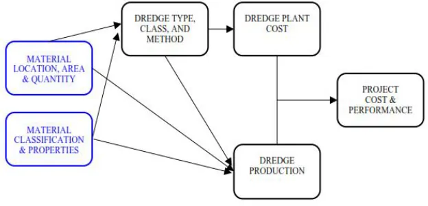
"Where and how much?" can be more technically described as the location, area, and quantities of the materials to be dredged. "What?" can be more technically described as the classification and physical properties of the materials to be dredged.
also primary factors in choosing the type and class of dredging equipment required and in determining the production of the dredging plant. Since the cost of dredging equipment is a function of its type and class, and the cost of a dredging project is a function of the dredge equipment cost and its productivity, then the material location, area, and quantity along with the classification and physical properties of the material to be dredged are all primary drivers of dredging costs and eventual project performance. The relationship of these primary drivers to project equipment, production, costs and performance is generally illustrated in Figure 1.1
Fig 1.1 Relationship of project factors
The location of the dredged material both in area and in elevation is of great importance in dredging projects. In order to choose appropriate plant and estimate quantities, production, and costs, the contractor needs sufficient and accurate information to determine for each material type in the dredging area:
¾ the depth,
¾ the absolute and relative quantities, ¾ the dredge area,
¾ the layer stratigraphy, ¾ the layer thickness (face), and
¾ the hard (or unsuitable) material surface.
C. Material Classification and Physical Properties
In order to choose appropriate plant and estimate production and costs, the contractor needs sufficient and accurate information to determine for each material type in the borrow area:
¾ soil classification , % silts, sands, clays, or rock, % descriptions per ASTM standards (loose, dense, fine, coarse, etc.) ¾ soil physical properties, % grain size distribution (sands and silts), % insitu density (unit weight), % quality (rock).
D. PRE-CONTRACT INVESTIGATIONS
Before undertaking any dredging works, investigations need to be carried out to establish a wide range of parameters essential for design, planning and selection of methods and for the accurate estimation of the cost of undertaking the work. These investigations fall into five main groups:
1) Meteorological investigations: to establish the wind climate at the site and the incidence of fog, ice and rainfall, all of which can affect dredging operations.
2) Hydrographic surveys: to measure tides, currents and waves and to define the form of level of the seabed.
3) Geological and geotechnical investigations: to determine the nature of the materials which are to be dredged, used or disposed
of.
4) Environmental surveys: to identify the potential effects of the works on environment, both during execution and on completion, and to establish baseline conditions with which the results of later environmental monitoring can be compared.
III. STUDY ON DREDGING
A. Introduction
Dredging is an ancient art but a relatively young science. Traces of man’s work involving primitive dredging techniques have been discovered in many places, dating back to thousands of years BC. In such instances, the vessel was probably little more than a raft and the excavating means a man with a bucket. The development of this method of excavation into the spoon and bag dredger and the subsequent proliferation of dredging machines has been well described.
B. Case Study
The development of dredging methods has been influenced by geographical characteristics. Whereas the major developments in
mechanical excavating methods in the 19th century probably occurred in the lowlands of Europe, the development of hydraulic
dredging techniques, using the centrifugal pump, was pioneered by Americans. The latter had numerous sites suitable for reclamation by pipeline dredgers, whilst the European sites were more often confined, necessitating transport by barge to open sea.
C. Definition Of Dredging
Dredging is an excavation activity or operation usually carried out at least partly underwater, in shallow seas or fresh water areas with the purpose of gathering up bottom sediments and disposing of them at a different location. This technique is often used to keep waterways navigable. It is also used as a way to replenish sand on some public beaches, where too much sand has been lost because of coastal erosion.
D. Need For Dredging
From various sedimentary processes it can be seen that, in most sites the various forces of nature are delicately balanced. Any artificial disturbance, such as that caused by dredging or disposal of dredged material is likely to alter the balance in some manner. In some instances the balance of nature may have already been altered by some other artificial means such as the construction of a breakwater or jetty.
E. Types Of Dredging
Dredging works are classed in one of two categories: capital or maintenance. The formation of a new bed configuration by dredging, whether the configuration is stable or not, with the implication being that the work involves the payment of a single capital sum is known as capital dredging. Any other dredging work would be recurrent and since it is performed to maintain the desired bed configuration, it is known as maintenance dredging.
F. Types Of Dredgers
There are numerous types of dredgers, the performance and suitability of which are affected to varying degrees by the detailed nature of the sediments and by site characteristics such as water depth, sea conditions, currents and size of area to be dredged. Most dredgers can be divided into two broad groups depending on the method by which they excavate and transport the dredged material to the surface:
G. Types Of Dredgers
There are numerous types of dredgers, the performance and suitability of which are affected to varying degrees by the detailed nature of the sediments and by site characteristics such as water depth, sea conditions, currents and size of area to be dredged. Most dredgers can be divided into two broad groups depending on the method by which they excavate and transport the dredged material to the surface: Mechanical dredgers, which excavate the marine mud directly using grabs or buckets achieving greater dilution than is the case with hydraulic dredgers, and these mechanical dredgers are well-suited to remove hard pack-material or debris and to work in confined areas. Sediments are generally transported by barges. Cohesive sediments dredged and transported this way usually remain intact with large pieces retaining their in-situ density and structure through the whole dredging and placement process.
H. Hydraulic dredgers :These are mainly,
reclamation/ beach nourishment. While dredging, the cutter head describes arcs and is swung around the spud pole powered by winches.
2) Trailer suction dredgers: A Trailer suction hopper dredger is a self propelled ship which fills its hold or hopper during dredging, while following a pre-set track. The hopper can be emptied by bottom doors or valves (dumping) or by pumping its load ashore. This kind of dredger is mainly used in open water: rivers, canals, estuaries and the open sea. These dredgers use hydraulic centrifugal pumps to provide vacuum for dislodging and lifting force and remove the material in a liquid slurry form in case of cohesive material. Teeth or water jets may be applied for breaking of the materials. Cutter suction dredgers are suitable for high strength materials such as stiff clays, packed or compacted sands and rocks. In total, the transport of dredged material to the reclamation or disposal area is usually achieved by one or a combination of the following three methods: Hydraulic transport through pipelines. Hopper transport within the hold or hopper of the dredger Placement of dredged fill materials can be achieved by the following methods: Simple bottom-dumping from barges or trailer dredger Hydraulic filling, involving the pumping of the fill in the form of a slurry to the placement area Rain bowing, i.e., spraying directly into the filling area through a nozzle mounted at the bow of a trailer suction hopper dredger. Various types of drag heads are:
I. Disposal Techniques And Beneficial Uses Of Dredged Material
Reclamation: Reclamation is perhaps the best known use of dredged material. The act of raising the level of land which is either just below or adjacent to water is known as reclamation. When the level is being raised with fill material which has been dredged from underwater, the material is usually known as hydraulic fill in the context of material which is placed by hydraulic pipeline. Reclamation is often carried out due to the following reasons: It is cheaper to place the dredged material in a reclamation area than to dispose of it at an acceptable onshore or offshore location.
1) It is environmentally more acceptable to reclaim with dredged material than to dispose of it at an offshore location.
2) There is a need for the reclaimed land for Port, industrial or residential development or for agricultural or recreational use.
3) Beach Nourishment:.
4) Other beneficial uses of dredged material:
J. Types Of Dredging Contracts
1) Fixed price contracts,
2) Charter Contracts,
3) Scope of Contract
4) Form of Contract
5) Measured contracts
K. Dredging Costs And Prices
For most of dredging works, the total cost will include two important elements: the cost to mobilize and demobilize all necessary plant, labour and equipment, and the cost of actually carrying out the work.
1) Mobilization and demobilization
2) Plant capital costs
3) Plant running costs
4) Fuel Cos
5) Lubricant Costs
6) Other consumables
7) Crew
8) Survey
9) Supervisio
10) Routine maintenance and Running repairs
11) Major repairs and Overhauling
12) Wea
13) . Overheads
14) Financial Charges
IV. COMPARING COST ANALYSIS OF DREDGING WITH AND WITHOUT SOIL INVESTIGATIONS
A. Schedule Of Planning & Material (With Soil Investigation) 1) Details of Work
Phase-III dredging of Inner Harbour channel and turning circle to(-) 16.10 meters CD for handling 14.0 meters draft vessels in the inner harbour at Port of Visakhapatnam.
B. Methodology
The methodology involves the following steps.
1) Pre/ Progressive/ Post - Dredging Survey
2) Jet Probing
3) Dredging of Soft Soil
4) Drilling
5) Blasting/ Pre-treatment
6) Dredging of Rock
7) Transportation and dumping of Dredged material
8) Sweeping and Handing over of Dredged area
C. Pre/ Progressive/ Post - Dredging Survey
All in conformity with Technical Specifications clause 8.0 • Equipment
• Survey launch along with personnel • Calibration certificates of equipment
• Dual frequency Echo Sounder, DGPS • HYPACK MAX soft ware
• Joint Survey using calibrated equipments • Soundings across 10m interval
• All soundings are reduced to Chart Datum with tidal
allowance
• Survey includes additional 25/50 mtrs on either side of the
Designated areas, wherever possible
• Process repeated for Pre, Intermediate and
Final Surveys.
• Sounding accuracy nearest 100 mm or below
D. Drilling &Blasting (2m × 2m)
• Drilling pontoons/ barges mounted with compressors
and all necessary equipments
• Depth of drilling - normally 1 mtrs more than
required depth
• Drill rods and outer casing tubes of 150mm Ø • Echo Sounder/ DGPS
• Drilling plan , Procedure. • Drilling depth/ Grid size will be as per expert advise.
• Overburden Drilling is an accepted method for
underwater drilling.
• Outer casing tubes shall have a ring of cemented
carbide at the bottom.
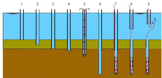
[image:7.612.167.443.587.720.2]E. Casing tube and Inner drill are connected to a rock drill
1) Step 1: Casing is lowered
2) Step 2: Lower the casing in the overburden if any. At a certain moment the casing will no further penetrate the over burden
Then casing will be pulled up a bit and be rotated.
3) Step 3: Rotate and lower the casing until it reaches the top of rock. When the rock is reached casing will be pulled up a bit, then lowered and rotate again to make sure top of rock is reached.
4) Step 4: Drill the casing a bit in the top of the rock.
5) Step 5: Insert drill rods and drill until required depth is reached.
6) Step 6: Air flush the hole and take out the drill rods.
7) Step 7: Charge the hole with explosives and check the depth of the explosives with stemming rod.
8) Step 8: Retract the casing.
9) Step 9: Recover the detonator wire under the water.
F. Blasting
1) All the procedure as per instructions of qualified Blaster and in accordance with Safety procedures
2) Explosive Handling
3) From Magazine to site by Storage Van
4) Pocket size of explosives - 0.5/1.0/1.5 kg
5) Actual quantity - Based on Depth of cut
6) Cut depth will be within the tolerance limits & Procedure ,Diver Inspection
7) Collection of Detonator fuse wires & Safety Instructions
8) Alertness declaration before exploding, &PPV measurement at shore
Once the hole is drilled the drill rods are retrieved and pre-fabricated couplable plastic explosives are placed immediately followed by stemming. After positioning the explosives at the required depth the driver goes along the casing pipe and brings the lead wire of the charged explosives. Then the blaster gives connections as per the detonation plan/sequence, after completing 10 holes in each row. The barge is moved by 2.0 m and entire activity is repeated for another three rows. Another barge would also complete 40 holes and the same will be charged at a distance from the first barge holes. The barges moved to safe distance (100 to 150m). After the clearance is given, blasting will be done in first drill zone and subsequently in second, third and fourth zone will be blasted. A typical cycle time might be as follows: 4 rows, 10 holes per row.
Time (Minutes)
1. View Co-ordinates through GPS 10
2. Positioning barge anchors & stabilize barge 10
3. Lower the casing and form the seal 15
4. Lower the drill rods and drill the holes (5m) 20
5. Check holes and charge explosives 20
6. Recover lead wires and lift the casing 10
Total 85 min
For 4 rows (10 holes per row) total time taken will be:
4 × 85 (barge shifting by 2.0m once) Total 340min
7. Removing barge anchors 10
8. Shift barge to firing position & Siren and fire the shots 10
Total 360 min (say 6 hours)
No. of Shifts 3 No’s
No. of holes per day (40×3 = 120) 120 No’s
Area to be excavated per day (1 barge) 2 ×2×120 = 480 Sq.m
G. Rock Dredging
1) Back Hoe unit , Hopper Barges&Tugs
2) Pre treated rock and the overburden shall be removed with Back Hoe dredger and loaded in to the split hopper barges, placed
by the side of back hoe dredger.
4) Towing of the barge shall be done as per the regulations of the Visakhapatnam Port Trust.
5) Dumping of the rock at the dumping ground.
6) Return of the empty barge to the dredging area.
H. Based on Soil Investigation/Geo physical Investigation, the equipment list required for dredging is given below:
Jet Probing barges - 2 No’s (6months)
Drilling Barges - 3 No’s (11 months)
Back hoes - 2 No’s (11 months)
SHD (4500 Cu. m) - 1 No (2 months)
Hopper barges - 4 No’s (12 months)
Ancillary crafts - 6 No’s (12 months)
I. Comparision Of Expenduture With And Without Soil Investigation
The overall cost comparison with and without soil investigation for 1, 2 and 3 month delay in project completion is worked out and presented here.
Sl.
No. Description
Based on Soil Exploration Completed as per Schedule Rate per month (INR) Months required Total Amount(INR)
1 Jet Probing Barges (2 No’s) 1800000 6 10800000
2 Drilling barges (3 No’s) 3000000 11 33000000
3 Back Hoe Dredger (2 No’s) 3000000 11 33000000
4 TSHD (1 No) 75000000 2 150000000
5 Hopper Barges(4 No’s) 4800000 11 52800000
6 Ancillary Crafts ( 6 No’s) 3600000 12 43200000
[image:9.612.37.582.460.734.2]TOTAL 322800000
Table 3.1 Cost for project completion in time with soil investigation
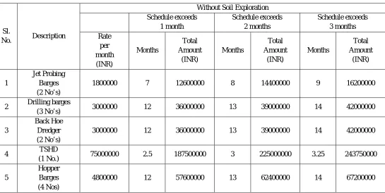
Sl.
No. Description
Without Soil Exploration Schedule exceeds 1 month Schedule exceeds 2 months Schedule exceeds 3 months Rate per month (INR) Months Total Amount (INR) Months Total Amount (INR) Months Total Amount (INR) 1 Jet Probing Barges (2 No’s)
1800000 7 12600000 8 14400000 9 16200000
2 Drilling barges
(3 No’s) 3000000 12 36000000 13 39000000 14 42000000
3
Back Hoe Dredger (2 No’s)
3000000 12 36000000 13 39000000 14 42000000
4 TSHD
(1 No.) 75000000 2.5 187500000 3 225000000 3.25 243750000
5
Hopper Barges (4 Nos)
6
Ancillary Crafts (6 No’s)
3600000 13 46800000 14 50400000 15 54000000
TOTAL 376500000 430200000 465150000 173344
[image:10.612.74.580.78.146.2]% increase in Cost 17% 33% 44%
[image:10.612.131.485.166.344.2]Table 4.2 Cost for project completion with delay without soil investigation
Figure 3.2.2 Cost comparisons for project completion with and without delay
This thesis described the geotechnical information required by contractors for estimating, planning and performing dredging and the relationship of geotechnical properties to dredging production, costs, and performance. General guidelines and criteria are presented for performing geotechnical site investigations for dredging projects and for providing geotechnical site information in plans and specifications.
. Ultimately, poor geotechnical information can lead to budget overruns, late schedules, poor quality, disputes, claims, and even incomplete projects. As per the old adage, "garbage in, garbage out" is illustrated in Figure 4.3.
Figure 3.3Garbagein,garbageout
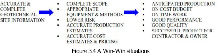
Accurate, complete and comprehensive geotechnical site information significantly lowers risk levels and leads to the application of appropriate equipment and methodologies, accurate production estimates, and appropriate pricing levels. For both the owner and the contractor, the result is a successful project completed on time, within budget, and to high quality standards creating a "win-win situation" as illustrated in Figure 4.4.
Figure 3.4 A Win-Win situations
Thus, the geotechnical information provided is ultimately for both the owners and contractor's benefit or risk. For better or for 0
17
33
44
0 10 20 30 40 50
0 0.5 1 1.5 2 2.5 3 3.5
%
In
cr
ea
se
[image:10.612.159.445.459.542.2] [image:10.612.119.491.618.709.2]worse, "what goes around comes around" is illustrated in Figure 3. Bad geotechnical information will most likely result in a poor project for both Owner and Contractor. Good geotechnical information can lead to a successful project for both Owner and
Contractor
Figure 3.5 What goes around
J. Typical Photographs At Site
Fig 4.6 Dredging & Drilling/Blasting is in progress Block-F Figure 4.7 View of Blasting by Drill Barge ‘SaiHaritha’
Figure 4.8 Trailer Suction Hopper Dredger dredging at IHC area
Fig 4.9 Dredging work is in progress by Dharti XXIV at Inner Channel area
K. Comparing Cost Analysis Of Dredging With And Without Soil Investigations
The location, area, classification, quantity, and physical properties of the material to be dredged are primary drivers of the type and class of dredging equipment required, of dredging production and costs, and of the ultimate success of dredging projects. Geotechnical site investigations must provide comprehensive and accurate geotechnical data representative of the materials throughout the project, such that the contractor can reliably estimate, price, plan and successfully perform the
Pandora
Dharti-14
dredging project. A number of guidelines, procedures and geotechnical tests, both in-situ and laboratory, are appropriate and are required to provide comprehensive and accurate information of the geotechnical properties of soils and rock for dredging projects.
1) The work was awarded 210crores which includes soil investigation/geo physical report.
2) Based on soil Investigation dredging work completed as per planning of equipment/machinery.
3) The absence of soil exploration report planning is not possible and the following issues may arise
4) Duration of project time is increased due to improper inadequate placing of machinery/equipment.
5) Lack of planning will lead to improper of disposal of dredged material leading to environmental concerns.
6) Free shipping movements are hindered.
7) Without soil exploration type of soil is dredged is not known hence the dredging equipment positioned in site may or
may not be used.
Based on above factors the cost of dredging a site with and without soil exploration for one month delay, two months and three months delay are determined. It is found that cost of dredging a site without soil exploration is 17% to 44% more than that with soil exploration for assumed delay in completion of project by one month and two months respectively.
REFERENCES
[1] “OPERATIONAL CHARACTERISTICS ANDEQUIPMENT SELECTION FACTORS FORENVIRONMENTAL DREDGING”, Journal of
Dredging Engineering, Volume 6 No.3, December 2004,Official Journal of the Western Dredging Association.
[2] “GEOTECHNICALINVESTIGATIONSFORDREDGINGPROJECTS”, KyleD.Johnson.
[3] B. A. Mir, “SOME STUDIES ON GEOTECHNICAL CHARACTERIZATION OF DREDGED SOIL FOR SUSTAINABLE DEVELOPMENT OF
DAL LAKE AND ENVIRONMENTAL RESTORATION”.
[4] Richard A. Fischer, “CONSERVATION ACTIONS ALONG INTERIOR RIVERS OF THE UNITED STATES: CONTRIBUTIONS TO THE RECOVERY OF THE INTERIOR POPULATION OF LEAST TERN” Journal of Dredging Volume 14, No. 2, December 2014 Official Journal of the Western Dredging Association.
[5] R. C. Newell, L. J.Seiderer& D. R. Hitchcock, “THE IMPACT OF DREDGING WORKS IN COASTAL WATERS: A REVIEW OF THE SENSITIVITY TO DISTURBANCE AND SUBSEQUENT RECOVERY OF BIOLOGICAL RESOURCES ON THE SEA BED” Marine Ecological Surveys Limited, West Country Office, Trewood Cottage, Steeple Lane, St Ives, Cornwall TR26 2PF, UK 2 Coastline Surveys Limited, Bridgend Farmhouse, Stone house, Gloucestershire GL1O 2AX, UK
[6] AnjanaPrakash, AnjuPaul,“A Study on Stabilization of Marine Dredged Soil Using Quarry Dust”, International Journal of Scientific Engineering and Research”, (IJSER), Volume 4 Issue 3, March 2016.
[7] NorpadzlihatunManap, NikolaosVoulvoulis, “Environmental management for dredging sediments - The requirement of developing nations”, Journal of Environmental Management Department of Construction Management, Faculty of Technology Management and Business, UniversitiTun Hussein Onn Malaysia, Beg Berkunci 101, Parit Raja, BatuPahat Johor 86400, Malaysia b Centre for Environmental Policy, Imperial College London, 1515, 15 Prince's Gardens, South Kensington Campus, London SW7 2AZ, United Kingdom
[8] Sara C. Koropchak, W. Lee Daniels, Abbey Wick, G. Richard Whittecar, and Nick Haus, “Journal of Environmental Quality”, Beneficial Use of Dredge Materials for Soil Reconstruction and Development of Dredge Screening Protocols
[9] S. Narasimhan, S. Arivalagan, “REPROCESS OF DREDGED SEDIMENTED PARTICLES FROM COASTAL AREAS AS PARTIAL
REPLACEMENT WITH RIVER SAND IN CONCRETE – A REVIEW”, International Journal of Civil Engineering and Technology (IJCIET) Volume 8, Issue 3, March 2017.
[10] Li Jingui , Li Jinjun , Yang Jianhua , Ding Shuyou,“TECHNICAL RESEARCH ON THE PRECISE DREDGING OF CONTAMINATED SEDIMENT”.
[11] Reda M. Bakeer,“Geotechnical Factors in DREDGeABiLity” (DREDGABL).
[12] ASTM, Annual Book of ASTM Standards,Vol. 4.08,Soil andRock (I),D420-D5779, AmericanSocietyforTesting and Materials,Philadelphia, PA [13] ASTM, Annual Book of ASTM Standards,Vol.4.09, Soil and Rock(II), D5780-lastest, American Society for Testing and Materials, Philadelphia, PA [14] US Army Corps of Engineers, Jacksonville District, “Bal Harbor Beach Renourishment2003, Beach Erosion Control and Hurricane Protection
Project", Construction Solicitation and Specifications, 2003.
[15] Johnson, K.andSraders, G. (2003)"Geotechnical Investigations for Dredging Projects-A Contractor's View", Proceedings of the Western Dredging Association Twenty-Third Technical Conference & Thirty-Fifth Texas A&M Seminar, June1-013, 2003.
[16] PIANC (1984) “Classification of Soils and Rocks to be dredged.”BulletinNo.47, Permanent International Association of Navigation Congresses, Brussels, Belgium.
[17] Verbeek, P.R.H. (1984) “Soil Analysis and Dredging.”TerraetAqua(28), International Association of Dredging Companies, 11-21.
[18] R.N.Bray, A.D.Bates and J.M.Land: “DREGING”: A Hand book of Engineers copy published in © 1977 North, Central and South America by John Wiley &Sons. Inc. 605 Third Avenue. New York. NY 10158-0012