6
I
January 2018
Comparative Study of Solar Flat Plate Collector
with Circular Tube using different Nano Fluids
Niranjan Mahato1, Vardan Singh Nayak2, Arvind Gupta3
1
M.Tech Scholar Mechanical Engg. Dept. VIST BHOPAL 2
Asst. Professor Mechanical Engg. Dept. VIST BHOPAL 3
Asst. Professor Electrical & Electronics Engg. Dept. VIST BHOPAL
Abstract: Solar energy is one the most popular renewable energy sources that can be used in a Thermal or Photovoltaic system. Solar collectors Play a key role in solar thermal systems. They convert solar radiation into heat and transfer the heat to working fluids Such as water or air. Flat-plate collectors are the most common type of solar collector and are typically used as a water heater or air heater. These collectors have a low efficiency and low outlet temperature. Recently, many researchers have attempted To enhance the efficiency and performance of flat-plate collectors via different methods. One of the methods For improving the performance of flat-plate collectors involves Using nano fluids instead of common fluids in solar collectors. Nanofluids are suspensions comprising base fluids such as water and nano particles 1–100 nm in size. These types of working fluids have more thermal properties than their base fluids. Solar liquid collectors are potential candidates for enhanced heat transfer. The enhancement techniques can be applied to thermal solar collectors to produce more compact and efficient energy collection/storage mechanism. Those collectors can be induced for simplest and most direct applications of energy conversion of solar radiation into heat. The present study examines and compares the heat transfer characteristics of different fluids for solar plate collectors for increasing the performance and efficiency SFPC. From CFD Simulation results we can conclude that among the four nano fluids which we have used in the current study for increasing the heat transfer characteristics of the solar collector, CuO + Water nano fluids have a great heat transfer rate as compared to others. Absorbing Temperature and Reynold Numbers are much higher in case of CuO + Water nano fluids than the other nano fluids we used.
Key words: Solar collector, Nano fluids, Radiation model, Numerical Simulation, CFD, Experimental Analysis, Fluent , etc.
I. INTRODUCTION
Nanofluids-Nano fluids demote to a solid-liquid mixture or suspensions produced by dispersing tiny metallic or nonmetallic solid Nano particles in liquids. Nanofluids are a new class of fluids engineered by dispersing nanometer sized materials (Nano-particles, Nano-fibers, Nano-tubes, Nano-wires and Nano-rods) in base fluids. The size of nanoparticles (usually less than 100nm) in liquids mixture gives them the ability to interact with liquids at the molecular level and so conduct heat better than today’s heat transfer fluids depending on Nano particles. Nanofluids can display enhanced heat transfer because of the combination of convection & conduction and also an additional energy transfer through γ-particles dynamics and collisions. Metallic nanofluids have been found to possess enhanced thermo physical properties such as thermal conductivity, thermal diffusivity, viscosity and convective heat transfer coefficients compared to those of base fluids like oil or water. In current years, nanofluids established greater potential in many fields like solar collector and solar thermal storage. Even though some review articles involving the progress of nanofluids investigations were published in the past several years most of the reviews are concerned with the experimental and theoretical studies of the thermo physical properties or the convective heat transfer of nanofluids.
A. Classification Of Nanofluids
B. Classification Of Solar Collectors
[image:3.612.233.363.169.261.2]Solar radiation is converted into thermal energy in the focus of solar thermal concentrating systems. These systems are classified by their focus geometry as either point-focus concentrators (central receiver systems and parabolic dishes) or line-focus concentrators (parabolic-trough collectors (PTC) and linear Fresnel collectors). Most popular types of solar collectors are parabolic Dish, Parabolic Trough and Power Tower system.
Figure 1.1: Parabolic Dish Collector
Firstly, the parabolic dish system Figure (a) uses a computer to track the sun and concentrate the sun's rays onto a receiver located at the focal point in front of the dish. Parabolic dish systems can reach 1000 °C at the receiver, and achieve the highest efficiencies for converting solar energy to electricity in the small-power capacity range.
Figure 1.2: Parabolic Trough Collector
[image:3.612.244.366.585.681.2]Secondly, the parabolic troughs concentrate sunlight onto a receiver tube that is positioned along the focal line of the trough Figure (b). Occasionally a transparent glass tube envelops the receiver tube to reduce heat loss. Parabolic troughs often use single axis or dual-axis tracking system which permits temperatures at the receiver can reach 400 °C and produce steam for generating electricity.
Thirdly, the heliostat uses a field of dual axis sun trackers that direct solar energy to a large absorber located on a tower Figure (c). A solar power tower has a field of large mirrors that follow the sun's path across the sky. The mirrors concentrate sunlight onto a receiver on top of a high tower and computer tracks the mirrors aligned consequently the reflected rays of the sun are always aimed at the receiver, where temperatures reach above 1000°C and produce high pressure steam for generating electricity. Finally, this categories of collectors were used which reduces heat losses and increases efficiency at high temperatures and thermal detoxification.
Figure 1.4: Sketch of a flat-plate solar collector
The flat-plate solar collectors are the non-focusing-light components which receive the solar radiation and transfer heat to the heat transfer fluid in the solar collector system. The structure of absorber is form of flat (Dhariwal and Mirdha, 2005), which is shown in Figure d. Its working principle is as follows: the sunlight through the glass cover tothe absorber which transforms solar into heat and transfers heat to the heat transfer fluid, which finish the process of solar-thermal conversion. At the same time, during the process of heat transfer, the collector will lose part of heat because of conduction, convection and radiation. The present study on the flat-plate solar collector is mainly focus on its thermal performances.
C. Solar Installations Worldwide
into the plant as the real time data cannot be passed onto researchers at other places who could potentially improve the results of the plant . Researchers in Algeria have built experimental solar ponds within the University of Annaba to study the effects of the use of different salts in the ponds as the brine solution. The heat transfer between the pond and the surroundings has been analyzed using the law of conservation of energy. The theoretical results have then been compared with the experimental results which have almost negligible level of errors. The temperature monitoring was done with the help of a thermocouple at a frequency of three hours. One of the major contributions of this study was the identification of the thermal conductivity of salts such as Sodium Carbonate and use of Calcium Chloride as a brine solution for newer sites because of its high conductivity. Solar ponds have been constructed in Turkey with surface areas and almost uniform depth for two separate cases to study the effect of the amount of sunny area in a zone of a solar pond mainly the LCZ. It is expressed as a ratio of total area with solar radiation incident on the area. This study allows for modeling of solar ponds prior to construction with better accuracy as we the researchers go beyond numerical modeling of the pond and it is a very important aspect to any environment. By knowing the temperature variance in an area coupled with the cloud cover for different times in the year, the study could determine a novel approach to thermal efficiencies obtained from ponds in different parts of Turkey. Researchers in Cyprus have constructed a pond and used Computational Fluid dynamics to study the pond using Ansys as a software. The purpose of this study was to compare the results obtained from the pond with other forms of Solar harvesting namely flat plate collectors and panels. The study also revolved around the comparison of salt concentrations at different depths of the pond as time passed and the weather conditions in the area changed. This model has an interesting take on solar ponds as this model has not been presented in the past and hence no basis of comparison unless carried out under different circumstances. One of the best examples of a solar pond is the one in Catalonia. There is a circular 50 m2 pond. The depth of the pond is 3m and the salt used is NaCl. The density profile of the pond along the depth is varied between 1.12g/cm3 to just over 1.2g/cm3. The salt concentration was roughly 25% by weight while filling the pond up which was done with a help of a diffuser. It is one of the more effective ways of creating salinity gradient associated with solar ponds. One important feature presented in this article was the use of the Froude number to determine inlet flow velocity which is useful to take into consideration when designing solar ponds at any site around the world. Froude number is defined as the ratio of the flow inertia to the external environment field. The pond recorded a peak temperature difference of about 16°C based on monthly averages. The entire list of sensors used to measure other parameters is summarized in the article. The study mentions the equipment used but does not mention how the data was analyzed and where it was transmitted to. The other major takeback from the study was the identification of the variability associated with the conditions prevalent to the UCZ. Solar pond systems can be compared to other renewable energy collection systems which may or may not involve solar energy. Each system usually has its own unique characteristics but may require the measurement of similar physical quantities which might need to be transmitted and analyzed away from the source. One such system which uses data transmission, and analysis has been studied, uses the server client mechanism over a TCP/IP protocol. This study is a generic investigation for renewable energy sources, used for energy generation, and is commendable as the results from the sensors for the renewable energy can be shown on the client computer in a user-friendly format using a Java applet. The software for the system which maintains the readings is also written in Java. This paper however does not get into the specifics of how accurate the readings are or the plethora of applications it can be applied but merely mentions it.
II. LITERATURE
work presents a comparative representation of computational simulation and experimental for the processes occurring in liquid flat-plate solar collectors. The working fluid used is propylene glycol and the concentration of propylene glycol (PG) is varied for various mass flow rates. The effect of this variation, on the efficiency of a flat plate solar collector was investigated computationally and experimentally. The experiments were carried out using 4 different mixture concentrations. The designed model is simulated under various flow conditions by varying the mass flow rate and varying the working fluid concentration. In order to verify the designed model and results, an experiment was designed and conducted for several days with variable ambient conditions, flow rates and concentrations. The comparison between the computed and measured results of the fluid temperature at the collector outlet showed a satisfactory convergence. The model is appropriate for the verification of overall efficiency of the system and can be used for any number of working fluids in order to find the outlet temperature. 3. Lippinpaulya*, L Rekhab, Christy V Vazhappillya, Melvinraj C Ra -Solar energy is one of the renewable energy sources which have potential for future energy applications. The current well-liked technology converts solar energy into electricity and heat individually. In this paper, an effort is made to simulate and evaluate the overall performance of a hybrid photovoltaic thermal (PV/T) air collector using computational fluid dynamics (CFD) software. The numerical analysis of the flow and heat transfer in hybrid PV/T systems is computationally quite complicated and the number of research works on this topic is quite low. Based on numerical analysis, the performance of a solar hybrid PV/T air collector has been studied. The numerical simulation was done in commercial software ANSYS FLUENT 14.5.0. The electrical energy conversion in solar cell was calculated with user defined function. The numerical results are validated with experimental results from literature. The results show a good agreement between experimental and simulated result for outlet air temperature and PV cell temperature. Using validated model, effect of mass flow rate and duct depth on the performance of solar hybrid PV/T collector has been studied and optimum values are identified. In order to increase the overall performance of a solar hybrid PV/T air collector, a novel design is proposed here. The result shows in the proposed design gives 20% enhancement in overall performance
compared to conventional solar hybrid PV/T air collector. 4. Adrian Ciocăneaa*, Dorin Laurențiu Burețea -The effect of vibrations
over a flow tube from a solar water heating collector was studied in order to enhance the heat exchange. First, a hydrodynamic model for the internal flow of the tube was proposed, in order to obtain the pattern for the relative motion of the liquid. The results highlighted a strong exchange of liquid volumes between the upper and the lower part of the pipe over the transversal section of the tube for a vertical displacement of the flow. In order to validate the positive effect of the internal motion over the heat transfer between the pipe and the water flow, an experiment was accomplished. The flow tube filled with liquid was introduced in a water recipient and vibrated at several frequencies. The water temperatures inside and outside the tube were recorded. The values for water temperatures measured during the warming and cooling intervals confirm that by vibration, the time for heat exchange is decreasing if the vibrating frequencies near the resonance frequency are considered.
III. OBJECTIVE OF THE STUDY
This investigation will presents a summary about Nano fluid with solar collector applications, an existing emerging class of heat transfer fluid, in terms of barriers, future research and environmental contests. Nano fluids are used to enhance the performance of many thermal engineering systems.
The main objective is to prepare a CFD model and using Nano fluid as flowing fluid, which examine the efficiency of square flat plate solar collector and enhancement in heat transfer with the use of different Nano fluid as compare to water . Therefore we are agreeing the simulation method to resolve the problem of Use of Nano fluid in the flat plate collector and to come to be the improved results by using computational fluid analysis in ANSYS 14.5 by FLUID FLOW (FLUENT) solver.
IV. METHODOLOGY
A. Pre Processing
1) CAD Modelling: Creation of CAD Model by using CAD modelling tools for creating the geometry of the part/assembly of which we want to perform FEA. CAD model may be 2D or 3D.
2) Type of Solver: Choose the solver for the problem from Pressure Based and density based solver.
3) Physical model: Choose the required physical model for the problem i.e. laminar, turbulent, energy, multiphase, etc.
4) Material Property: Choose the Material property of flowing fluid
B. Solution
1) Solution Method: Choose the Solution method to solve the problem i.e. First order, second order.
2) Solution Initialization: Initialized the solution to get the initial solution for the problem.
3) Run Solution: Run the solution by giving no of iteration for solution to converge.
C. Post Processing
For viewing and interpretation of result, this can be viewed in various formats like graph, value, animation etc.
D. CFD Simulation Method
The ANSYS 14.5 finite element program was used for analyzing Pipe flow. The equation of motion of Pipe is solved using FEA tool (ANSYS 14.5 – Fluid flow Fluent) as the equation of motion for a Pipe is difficult to visualize therefore some FEA tool is the only solution method for analyzing hydrodynamic characteristics. To find out the Reynolds number for different Nano fluid we are adopting Reynolds stress model for CFD simulation.
E. Step1 -Geometry Generation
The geometry and mesh was created by using ANSYS FLUENT 14.5 .The FLUENT is an integrated postprocessor for CFD analysis. The sequences of fluent steps are shown in Figure 4.1.
F. Pre-processing
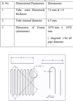
[image:7.612.178.432.360.712.2]Therefore the geometry will be taken for the simulation for different Nano fluid like SiO2 + Water as Case 1, AL2O3 + Water as Case 2, Ti2O + Water as Case 3&CuO + water as Case 4 was shown below in figure 4.1
Table 1 Parameters of geometry
S. No Dimensional Parameters Dimensions
1 Tube outer Diameter&
thickness
7.6 mm & 1.0
2 Tube internal diameter 6.5 mm
3 Dimension of Frame
(aluminum)
1070 mm x 1070 mm
( diagonal ) for all pipe diameter
Figure 4.2: CAD model of flat plate solar collector
Figure 4.3: CAD model for 6.5 mm pipe diameter &for different Nano fluid
[image:8.612.183.434.217.336.2]1)Step 2 –Meshing: Mesh – Generate mesh model in the ANSYS Making meshed model of flat plate collector pipe. Meshing is a critical operation in CFD. In this operation, the CAD geometry is discretized into large numbers of small elements and nodes. The arrangement of nodes and elements in space in a proper manner is called mesh. The analysis accuracy and duration depends on the mesh size and orientations. With increase in mesh size (increasing number of element), the CFD analysis speed decreases but the accuracy increases.
Table 4.2: Meshed geometry of tube diameter 5.1 mm pipe diameter
Mesh type Fine grid mesh
No. of nodes 1026512
No. of elements 631536
Figure 4.5: MESH MODEL
2)Step 3-Setupfor SimulationFluent Setup: After mesh setup generation define the following steps in the ANSYS fluent 14.5
[image:8.612.176.430.453.694.2]b) Type of Solver – pressure
c) Physical Model – Turbulence model
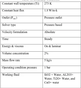
3)Step 4 -Boundary conditions
[image:9.612.170.441.158.451.2] [image:9.612.170.441.158.494.2]Boundary Conditions
Table 4.3:Boundary Conditions
Constant wall temperature (Ti) 273 K
Constant heat flux 1.8 W/m-k
Outlet (Pout.) Pressure outlet
Solver type Pressure based
Velocity formulation Absolute
Time Steady
Energy & viscous On & laminar
Volume concentration 2%
Mass flow rate 5 kg/s
Operating condition pressure 1 bar
Working fluid SiO2 + Water, AL2O3+
Water, Ti2O+ Water, and CuO+ water
[image:9.612.172.444.502.708.2]Fluid Property
Table No.4.4: Fluid Property Type of
fluid
SiO2 + Water
AL2O3+Water Ti2O+Water CuO+ water
Density (ρ)
kg/m3
2650 1037.4 1034.9 1136.7
Viscosity (µ x 104) (kg/m-s)
4.271 4.271 4.271 4.271
Specific heat (Cp)J/Kg-K
680 4119 4117 4111
Thermal conductivity ( k)W/m-K
4)Step 5– Solution: Solution Method Pressure - Velocity - Coupling – Scheme - Simple a) Pressure – standard pressure
b) Momentum- 2nd order
c) Turbulence –kinetic energy 2nd order d) Turbulence dissipation rate 2nd order
V. RESULTS & DISCUSSION
Validation and comparison between Water, Water+ Nano-fluid Al2O3(Experimental) and Water+ Nano-fluid Al2O3 (CFD Simulation)
Figure 5.1: Validation with experimental data and CFD simulation
The efficiency is compared with reference paper results for 6.5 mm pipe diameter for Al2O3+ water Nano fluid. For the water and Al2O3/Water Nano fluid the data were in used from the experimental results. Comparison between Experimental and CFD simulation is performed with the help of ANSYS (Fluent 14.5), which shows in graph. First we compare the efficiency between Fluid and water + Al2O3 as experimental results given, as we see in graph the efficiency of water is 0.66 and for Nano fluid its value is 0.725. CFD Simulation shows that when we taken Nano fluid Al2o3 with water its efficiency is near about 7.32. Now we can say clearly that the result obtained from CFD simulation for 6.5 mm diameter for (Al2O3 + water) Nano fluid is in good agreement with experimental results and we gained the increase value of efficiency, which is directly proportionate to heat transfer.
A. Comparison Between Different Nano Fluids With Reynolds Number And Static Temperature
(b)
Figure 5.2: (a) & (b) Represents Contour of total temperature &Reynolds number for SiO2 + water Nano fluid respectively . As of figure 5.2 (a), the value of Reynolds number is 6120 for 6.5 mm pipe diameter and for SiO2 + Water Nano fluid (i.e. Case 1).From figure 5.2 (b), the maximum outlet value of total temperature for SiO2 + water Nano fluid is 321 k for 6.5 mm pipe diameter and for SiO2 + Water Nano . This is maximum value as compared to experimental SiO2 + Water Nano fluid for pipe flow.
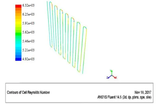
Figure 5.3: Contour of Reynolds number for (AL2O3+ water) Nano fluid.
From figure 5.3 the value of Reynolds number is 6320 for 6.5 mm pipe diameter and forAL2O3 + Water Nano fluid (i.e. Case 2). This is maximum among all other Nano fluid.
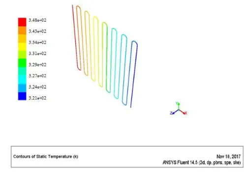
Figure 5.5: Contour of Reynolds number for (Ti2O + water) Nano fluid
Figure 5.6: Contour of Static Temperature for (Ti2O + water) Nano fluid.
From figure 5.4 the value of Reynolds number is 6520 for 6.5 mm pipe diameter and forTi2O + Water Nano fluid (i.e. Case 3). This is highest among all other Nano fluid.
Figure 5.8: Contour of Static Temperature for (CuO + water) Nano fluid.
[image:13.612.178.432.77.252.2]From figure 5.8 the value of Reynolds number is 37500 for 6.5 mm pipe diameter and for CuO + Water Nano fluid (i.e. Case 4). This is highest among all other Nano fluid.
Table 5.1: Reynolds numbers for different Nano fluid
VI. CONCLUSION
This investigation presents summary about Nano fluid with solar collector applications, an existing emerging class of heat transfer fluid, in terms of barriers, future research and environmental contests. Nano fluids are used to enhance the performance of many thermal engineering systems. It is originate from the researches that the heat transfer increases with increasing Reynolds number of the flow. Now, we change the Nano fluid for model, like SiO2 + Water called as Case 1, Al2O3+ Water called as Case 2, Ti2O+ Water called as Case 3 &CuO+ water called as Case 4 respectively by provide constant diameter of pipe 6.5 mm and Evaluation between different Nano fluid with constant velocity of 1.5 m/s. As of table 5.1 we found the result, after the contour of Reynolds number for different Nano fluid and it was observed that the maximum value for Reynolds number obtained with the CuO + Water Nano fluid i.e. Case 4 and here after we can say that the heat transfer will also increases with increasing Reynolds number of the flow. From CFD Simulation results we can conclude that among the four nano fluid which we have used in current study for increasing the heat transfer characteristics of solar collector , CuO + Water nano fluids have a great heat transfer rate as compare to others. Absorbing Temperature and Reynolds Numbers are much higher in case of CuO + Water nano fluids than the other nano fluids we used. The midpoint point was to evaluate the use of different Nano fluid in the developed region of the tube flow containing water + Nano fluid (Al203and Ti2O, CuO, and SiO2) on heat transfer characteristics. It was observed that all Nano fluids (Al203and Ti2O, CuO, and SiO2) revealed higher heat transfer characteristics than that of the base fluid (water).
REFERENCES
[1] Omer Khalil Ahmed “Experimental and numerical investigation of cylindrical storage collector (case study) Technical Institute / Hawija, Northern Technical University, Iraq Case Studies in Thermal Engineering Elsevier 10 june 201
[2] Ranjith P. V.a,*, Aftab A. Karimb A Comparative Study on the Experimental and Computational Analysis of Solar Flat Plate Collector using an Alternate Working Fluid International Conference on Emerging Trends in Engineering, Science and Technology (ICETEST - 2015)
Case Nano fluid Reynolds Number Static Temperature
(˚k)
Case 1 SiO2 + WATER 6120 321
Case 2 AL2O3 +
WATER 6320
325
Case 3 Ti2O + WATER 6520 334
[3] Lippinpaulya*, L Rekhab, Christy V Vazhappillya, Melvinraj C Ra Numerical Simulation for Solar Hybrid Photovoltaic Thermal Air Collector International Conference on Emerging Trends in Engineering, Science and Technology (ICETEST - 2015) 2016 Published by Elsevier Ltd.
[4] Ciocăneaa*, DorinLaurențiuBurețea The influence of flow tube vibrations over the efficiency of solar water heating collectors Adrian Sustainable Solutions for Energy and Environment, EENVIRO 2016, 26-28October 2016, Bucharest, Romania
[5] H. Jouhara , A. Chauhan , T. Nannou ,S. Almahmoud ,B. Delpech , L.C. Wrobel Heat pipe based systems - Advances and applications. Institute of Energy Futures, Brunel University London, Uxbridge, Middlesex UB8 3PH, London, UK Institute of Materials and Manufacturing, Brunel University London, Uxbridge, Middlesex UB8 3PH, London, UK 2017 The Authors. Published by Elsevier Ltd
[6] Romero, V.M.a, Cerezo, E.a, Garcia, M.I.a, Sanchez, M.H.a* aUniversidad del Caribe Simulation and validation of vanilla drying process in an indirect solar dryer prototype using CFD Fluent program, 2013 ISES Solar World Congress The Authors. Published by Elsevier Ltd
[7] OlofHallstroma, GerritFüldnerb Integration of sorption modules in Sydney type vacuum tube collector with air as heat transfer fluid , International Conference on Solar Heating and Cooling for Buildings and Industry, SHC 2014, The Authors. Published by Elsevier Ltd
[8] J. Paetzolda, S. Cochard , D. F. Fletcher , A. Vassallo Wind engineering analysis of parabolic trough collectors to optimise wind loads and heat losInternational Conference on Concentrating Solar Power and Chemical Energy Systems, SolarPACES 2014
[9] Milan Simic, Joshua George* Australia Design of a system to monitor and control solar pond: A review 1st International Conference on Energy and Power, ICEP2016, 14-16 December 2016, RMIT University, Melbourne
[10] Uzu-KueiHsua, Liang-JiChangb, Ying-JiWangb , Chang-Hsien Tai *International Workshop of Automobile, Power and Energy Engineering, APEE2011 Thermo-hydrodynamic analysis of the flow field in an underground concentrating solar tower under unsteady solar radiation
[11] Yang Wang, AshishShukla⁎, Shuli Liu - A state of art review on methodologies for heat transfer and energy flow characteristics of the active building envelopes, School of Energy, Construction and Environment, Faculty of Engineering, Environment and Computing, Coventry University, CV1 2HF Coventry, UK, Renewable and Sustainable Energy Reviews 78 (2017) 1102–1116
[12] LingkaiKongaˈWeixingYuana,*, and NingZhub CFD simulations of thermal stratification heat storage water tank with an inside cylinder with openings, 8th International Cold Climate HVAC 2015 Conference, CCHVAC 2015
[13] D. Roelevelda,*, G. Hailua, A.S. Funga, D. Naylora, T. Yangb, A.K. Athienitisb . Validation of Computational Fluid Dynamics (CFD) Model of a Building Integrated Photovoltaic/Thermal (BIPV/T) System 6th International Building Physics Conference, IBPC 2015 Department of Mechanical & Industrial Engineering, Ryerson University, 350 Victoria Street, Toronto, Ontario, Canada M5B 2K
[14] A. Heimsatha,*, F. Cuevasa, A. Hofera, P. Nitza, W.J. Platzera Linear Fresnel collector receiver: heat loss and temperatures, a Fraunhofer Institute for Solar Energy Systems, Devisiont Solar Thermal and Optics, Heidenhofstraße 2, 79110 Freiburg, Germany, Energy Procedia 49 ( 2014 ) 386 – 39
[15] Fritz Zaverskya,⁎, Leticia Aldaza, MarcelinoSáncheza, Antonio L. Ávila-Marínb, M. Isabel Roldánc, JesúsFernández-Rechec, Alexander Füsseld Numerical and experimental evaluation and optimization of ceramic foam as solar absorber – Single-layer vs multi-layer configurations, Wieland Beckertd,
JörgAdlerdaNational Renewable Energy Center (CENER), Solar Thermal Energy Department, c/Ciudad de la Innovación 7, Sarriguren, Navarre, Spain [16] YosrAllouchea*, ChihebBoudena, and SaffaRiffatb A solar-driven ejector refrigeration system for Mediterranean climate: Experience improvement and new
results performed , 1876-6102 © 2012 Published by Elsevier Ltd. Selection and/or peer review under responsibility of The TerraGreen Society. doi: 10.1016/j.egypro.2012.05.126 , aUniversity Tunis El Manar, Energy, buildings and Solar systems laboratory, National Engineering school of Tunis, B.P.37 le Belvédère 1002 Tunis, Tunisia Energy Procedia 18 ( 2012 ) 1115 – 1124
[17] Navneet Kumar Yadava, DarshanPalab, LaltuChandraa 2013 ISES Solar World Congress On the understanding and analyses of dust deposition on heliostat aIndian Institute of Technology Rajasthan, Jodhpur, 342011, India bSardarVallabhbhai National Institute of Technology Surat, Gujrat, 395007, India
[18] Huixing Li, Chihong Cao, GuohuiFeng*, Ran Zhang, Kailiang Huang , 9th International Symposium on Heating, Ventilation and Air Conditioning (ISHVAC) and the 3rd International Conference on Building Energy and Environment (COBEE) A BIPV/T System Design Based on Simulation and its Application in Integrated Heating System .
[19] ChristophZaunera*, Florian Hengstbergera, Wolfgang Hohenauera, ChristophReichla, Andreas Simetzbergerb, Gerald Gleissb Methods for medium temperature collector development applied to a CPC collector, Austrian Institute of Technology, Giefinggasse 2, 1210 Vienna, Austria bSolarfocus GmbH, Werkstrasse 1, 4451 St. Ulrich/Steyr, Austri
[20] HimanshuPandyaa ,*, Arun Kumar Behurab Experimental Study of V-Through Solar Water Heater for Tilt Angle and Glass Transmissivity, International Conference on Recent Advancement in Air Conditioning and Refrigeration, RAAR 2016, 10-12 November 2016, Bhubaneswar, India
[21] G. Colomera, J. Chivab, O. Lehmkuhla,b and A. OlivaAdvanced CFD&HT numerical modeling of solar tower receivers , SolarPACES 201