Water Level and Pump Controlling System
Osman Ishag Abdelrahim Abdalla¹, Dr. Eltahir Mohamed Hussein² ¹Department of Computer Engineering, Faculty of Engineering, Alneelain University ²College of Engineering, Sudan university of Science and Technology, Khartoum, Sudan
Abstract—Water is the most important Nature’s gift to the mankind. Without Water there is no life. Now man understood its importance, especially where water is not easily available. Now this is being managed by the proper manner in city areas where the use of water is more than its availability. Water pump controller is obviously from its name the level of overhead storage in industrial area or house. This controller automatically turn ON / OFF the domestic water pump set depending on the tank water level and the availability of water in main line source. In this paper a potential stress s done to design a system which can manage a water level in the storage to provide water throughout the day without any wastage. This Water Level Controller designed to be as good as any modern controller in addition to main pipe line water detection and cheap enough to buy by anyone.
Key Wards—555 Timer, water sensor, water pump, pressure sensor, signal condition, switching.
I.INTRODUCTION
Due to increased level of urbanization and customer demand, most water-distribution-system operations have become increasingly complex. The operational system requirements are typically impacted by the pressures from the general public to regulatory commissions to keep operational costs to a minimum. [1] Intelligent pump controller is a chain of tasks to control the storage water. To eliminating the risk of electrocution mechanical pressure sensor has been used for water level sensing, thus no any electricity DC or AC in the reservoir or water storage. Some researcher [1, 5, and 6] used a couple of sensors inside water tank in order to sense water level although it's not usable. A control system therefore can be defined as a device, or a group of devices that manage commands forthright or regularize the system behavior. Thus, an automatic controlling system sit in designing a system to interact with minimal or without manpower interference. Intelligent systems take place whole life nowadays such as medical applications, education, law, financial sciences etc. Several of them are embedded in the design of everyday devices. In this work intelligent water pump intended to implement. The impulse for this work was the absolute solution to the water shortage problem of in disparate area eliminating the main delinquent. dissipation of water during pumping and dispensing into overhead thanks.in fact that there are many research’s [1-7] about this topic but I think no one touches what I want introduced, in majority of areas sometimes there is no water in main pipe line, so when water level becomes low if the pump turned on it gets damage because of no water in main source, this what I am going to solve through this research.
II. RELATED WORKS
III. MATERIAL AND METHODS
In this work, the automatic water pump controller here presented consists of the following major units: water sensors, pressure sensor, 555 timer, and the pump switch unit and the core work of main source of water present detecting is done. The system block diagram figure. The flow of operations has been described in the system as well as their inter-operability. Taking advantage of the electrical conductivity property of water, [8] copper conductivity of electric has been used to sense the water in a main source. When water touches the copper plate (water sensor) which positioned in the main pipe line, small micro current flow form the sensor to the
Figure.1. Overall system block diagram
signal conditioning unit for further processing. [8] The BJT transistor amplifier circuit was used to amplifier the current and trigger the processor (555timer), and a pressure sense was used to sense the pressure in the reservoir and output a digital logic accordingly to pre-set value of sensor. This HIGH or LOW was fed into the processor which in turn uses this to control the water pump and display the appropriate status on the LED. The special power supply pigure.2 designed to supply the controller. Relay was used in building a switching unit that simply triggers the pump on or off, according to received signal from the control unit.
Figure.2 the system power supply circuit
Controller
Pressure
sensor
Switching and
actuators
Water sensor
Signal conditioner
Water tank
Pump
Power supply:
IV. THE 555 TIMER CONTROLLER
The 555 is available and very cheap chip on the market. [8, 9] It's belong to TTL family and has wide range of input power (4.5v-18v). It costs a few cents (eBay) to 1.20 dollar depending on the request quantity and suppler. The controller chip (555 timer) consume about ten mA - even if there no load applied. Although the timer it is not usable for battery operation if the chip is to be powered ALL THE TIME [9] .The”7555” costs from 60 cents (eBay) to 2.00 dollar. 555 is the TTL architecture while 7555 is CMOS technology. The timer controller comes in two package 8 or 14 pin through hole [8].
Figure.3. 555 timer pin lay out
The 555 and 7555 timer chip architecture are called TIMERS or Timer Chips. They consist of approximately 28 transistors although you need come extra element known as timing component. [8] The extra component are capacitors and resistors. The time period timer calibrated by the capacitor, it depend on charging and discharging of capacitor which connected to the voltage. A duty cycle depend on the capacitor and resistor values. The capacitor control on the rising and falling time. [8, 9] since a chip output frequency over 1 cycle per second, (1Hz), the circuit known as 'oscillator' and beneath 1Hz named a timer. Furthermore thing the developer must be aware pin 3 output voltage figure 3. The 555 timer pin layout. The voltage within 1-2v below rail voltage it does not reach 0 voltage "within 0.7 volt for ten mill ampere and above 1900 mill Volt for 200 mill ampere sinking current". For example, to achieve an output swing of ten voltage it needs a 12.6 supply voltage.
V. SIGNAL CONDITIONER UNIT
The innovation of the bipolar transistor in 1948 ushered in a revolution in electronics. Technical exploits already requiring comparatively large, [8] mechanically brittle, power-hungry vacuum tubes were suddenly achievable with tiny, mechanically rugged. This inversion made the manufacture and design of lightweight thinkable [8] Understanding how transistors function is of paramount importance to anyone interested in understanding modern electronics. Figure.4 shows the signal conditioner circuit schematic designed using bipolar transistor.
VI. PROTEUS TOOL
PROTEUs VSM brings you the best of both worlds. It combines a super mixed mode circuit simulator according to the industry criterion SPICE3F5 with animated component models. And it provides an architecture in which extra models may be created by any developer. Library models can be created without resort to coding. Consequently Proteus VSM lets regular developer to run a real simulations for the designs especially when the circuit does not contain passive component, and to gather the rewards of this mechanism to the schematic circuit simulation. And then, if that were not sufficient, we have a range of simulator models range must be created for popular controllers and a group of animated models for related modules such as LCD displays, LED, RS232 terminal keypads etc. Thus it can simulate entire microcontroller design circuits and so a physical prototype does not needed to develop the software for any system. In a world where time to market is becoming more and more important this is a real advantage I used Proteus Tool for design printed circuit board, its single layer single side PCB. After construction, tests were carried out to ensure that the device is functioning according to the design Specifications. When a pass through all tests successfully, the entire system prototype will be designed. All the sub-circuits were combined together with the microcontroller to obtain the model of the design. The figure.4.the system schematic diagram shows the integration of the sub-circuits making up the automatic water pump controller.
Figure.4 the system schematic diagram
VII.RESULTS AND DISCUSSION
functioning according to the design Specifications. After a successful testing, the design prototype of system designed, figure.5 shows the prototype and overall system implementation.
Figure.5 overall system implementation and prototype
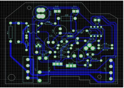
All the sub-circuits were combined together with the microcontroller to obtain the model of the design. The figure.5 shows the circuit connections of all the sub-sections making up the system that needed, all of them interfaced with the brain (555 timer). The implementation of this work came with quite a number of challenges. A lot of the integrated circuits (ICs) were get damaged in the Course of soldering them on the Vero board and I had to finally use PCB the figure.6 and figure.7 show the system PCB design used Proteus tool.
[image:6.612.117.514.442.724.2]Figure.7 the system PCB
VIII. SUMMARY AND CONCLUSION
Automatic water pump control system employs the use of different technologies in its design, development, and Implementation. The system used 555 time to automate the process of water pumping. in an over-head tank Storage system and has the ability to detect the level of water in a tank, to detect water in main source line and switch on/off the pump accordingly and display the status on an LED. This work has successfully provided an improvement on existing water pump controllers by its use of calibrated circuit to control and indicate the water level and without any voltage inside the water tank thus eliminating the risk of electrocution.
REFERENCES
[1] Ejiofor Virginia Ebere, "Microcontroller based Automatic Water level Control System," International Journal of Innovative Research in Computer and Communication Engineering, Issue 6, August 2013.
[2] Rojiha" Sensor Network Based Automatic Control System for Oil Pumping Unit Management" International Journal of Scientific and Research Publications, 2013.
[3] T. R. Brinner, J. D. Atkins, and M. O. Durham, "Electric submersible pump grounding", IEEE TRANS. IND. APPL., VOL. 40, NO. 5, PP. 1418–1426, SEP. /OCT. 2004.
[4] B. Eker, "SOLAR POWERED WATER PUMPING SYSTEMS" Trakia Journal of Sciences, Vol. 3, No. 7, pp 7-11, 2005
[5] Sanam Pudasaini, "Automatic Water Level Controller with Short Messaging Service (SMS) Notification" International Journal of Scientific and Research Publications, Volume 4, Issue 9, September 2014
[6] Mousumi Das, Anik Sau, Soumyadeep Patra"Android Based Smart Water Pump Controller With Water Level Detection Technique," International Journal of Advanced Research in Computer and Communication Engineering, ssue 12, December 2015.
[7] Jun DENG, Lie-jibe FENG, Jin-fang WANG, "Innovating design of submersible motor pump based on TRIZ," IEEE Transactions, Industrial Engineering and Engineering Management, Oct 2
[8] McGraw-Hill, "Practical Electronics for Inventors" 2000. ISBN0070580782. [9] 555 Timer data sheet. www.alldatasheet.com, Jun 2017.