Amidaddin SHAHRIARI, Hazlie MOKHLIS, Mazaher KARIMI, Ab Halim ABU BAKAR, Hazlee Azil ILLIAS,
Mohammad KAZEMINEJAD, Omid PALIZBAN
University of Malaya, Electrical DepartmentNumerical Estimation of Inter Line Power Flow Controller Based
on Injection Model of Synchronous Voltage Sources
Abstract. This paper presents the estimation model of Inter-Line Power Flow Controller (IPFC) based on injection model of synchronization voltage source. The linear model of voltage source inverter is used to estimate steady-state operation of Inter-Line Power Flow Controller. The proposed model can keep the capability of IPFC with the acceptable accuracy. The active and reactive power flow at receiving end line could be controlled separately in this proposed model. Furthermore, the proposed model has these abilities to decrease the reactive power flow and control of the sending bus voltage at the same time. The validation of the proposed method is shown by using two machine systems to estimate suitable approximation of power flow at receiving end line.
Streszczenie. W artykule opisano model estymacji międzyliniowego regulatora przepływu mocy (ang. IPFC), bazujący na synchronizacji napięć źródłowych. Proponowany model utrzymuje odpowiednią dokładność IPFC. Daje możliwość niezależnej kontroli mocy czynnej i biernej. Model został
zweryfikowany z wykorzystaniem dwóch systemów w celu estymacji aproksymacji mocy na końcu linii odbiorczej. (Numeryczna estymacja międzyliniowego regulatora przepływu mocy – modelowanie synchronicznych źródeł napięcia).
Keywords: Injected active and reactive power, Static Synchronous Series Compensator, Inter-line Power Flow Controller, Voltage source inverter, Numerical estimation.
Słowa kluczowe: dostarczona moc czynna i bierna, szeregowy synchroniczny kompensator statyczny, IPFC, falownik napięcia, estymacja numeryczna.
Introduction
Series compensators are implemented in power system to increase the active power flow at the receiving end line. However, the difficulties of series compensators based on thyristors controller are [1, 2]:
1- Increasing the reactive losses.
2- Sub-Synchronous Resonance (SSR) phenomenon with system inductance.
3- Operation of series compensators depends on line current.
4- Slow operation of series compensators by using the thyristor switch.
Static Synchronous SeriesCompensator (SSSC) can be utilized to solve the aforesaid problems. For instance, the implementation of SSSC in the power system network avoids the SSR phenomenon[3]. However, SSSC could not control the injected active and reactive power of Voltage Source Invertor (VSI) separately. On the other hands, SSSC has not enough capacity to decrease reactive power losses of a system. Two power compensators were introduced to overcome SSSC defects, the Unified Power Flow Controller (UPFC) and Inter-Line Power Flow Controller (IPFC). However, it is known that the capacity of IPFC in injecting active power to a line is more noticeable than UPFC. The Synchronous Voltage Sources (SVS) including the VSI and Voltage Source Converter (VSC) supplier of IPFC is covered by the active power surplus of other parallel line [4, 5]. For this case, IPFC is used to control the line sending active and reactive power separately. Also, IPFC can control the sending bus voltage simultaneously[6].
IPFC in three modes resistive, capacitive and inductive was used to improve problems of SSSC[7, 8]. IPFC in resistive mode adjusts the sending reactive and active power of main system to 0 and 1 respectively. The maximum injected active power from auxiliary system to the main system occurs in order to increase the sending active power in the main system to the maximum value. Furthermore, the sending reactive and active power flows of the main system in inductive mode are decreased [7-10].
Contribution of the proposed method is apparent in the use of linear model IPFC based on injection mode of VSI to estimate operation of IPFC in resistive, capacitive and inductive modes. The proposed model can support the
capability of IPFC with acceptable accuracy in these three modes. The proposed model could separate the control of active and reactive power flow at receiving end line for capacitive, resistive and inductive modes. Another ability of this model is decreasing the reactive power flow with the control of the sending bus voltage together. Thus, the formulation of IPFC of the mentioned modes is robust and simpler than previous approaches. In this context, the comparison of these equations of IPFC with values of simulation indicates the accuracy of the proposed method. The comparison is based on two machine systems. Furthermore, this proposed model of IPFC can also be implemented for power system reliability such as voltage stability and state estimation [3, 5, 11-13]
Basic operation of SSSC in Steady-State condition
Fig.1 shows the steady- state model of SSSC as Vq in
single line diagram. The phasor diagram of Vq effects on Vr
(sending voltage source) and Vr (receiving end voltage
source) system and I (line current) are shown in Fig 2. In capacitive mode of SSSC, the sending active and reactive power to end line increases due to the decrease of line reactance. The operation of SSSC in inductive mode is opposite of capacitive mode. Thus, the active and reactive power flow equations of system using SSSC are given as follows
(
line resistance is neglected):Fig.1. Single line diagram of SSSC
(1)
)
2
cos(
)
sin(
X
VrVq
X
VrVs
P
r
(2)
)
2 sin( )
cos(
2
X VrVq X Vr X
VrVs
Qr
where
1
2
s
V
I
r
V
X
V
q
V
xeff
V
j90q
q
X
I
e
Fig.2. Phasor diagram of SSSC
In Fig.2, Vxeffshows the compensation of Vq on voltage
drop of the line reactance. 15° is the maximum phase angle between sending end voltage source and receiving-end voltage sourcein real system. Therefore, the injected active power of VSI compared to the injected reactive power VSI in SSSCis very significant because [1, 2]:
(3)
X
VrVq
X
VrVq
P
SSSC)
0
.
99
2
15
cos(
(4)
X VrVq X
VrVq
QSSSC ) 0.13
2 15 sin(
Therefore, SSSC is unable to control reactive power and decreases losses reactive power in the studied system. The reactive power is unbalance between the reactive power load and injected reactive power[6, 8, 14, 15].
Equations (3) and (4) as the injected active and reactive equations of SSSC can be rewritten based on the effect of SSSC reactance compensation
X
q (both inductive andcapacitive modes) on line inductive reactance
X
L as follows,(5)
) 1 ( sin ) 1 ( sin
2 2
L q L
q L eff
q
X X P
X X X
V X
V P
(6)
) 1 ( ) cos 1 ( ) 1 ( ) cos 1 (
2 2
L q L L
q L eff
q
X X X
Q
X X X
V X
V Q
Dividing (5) by (6) then manipulating,
(7)
cos 1
sin 1
1
L q q
q
X X Q P Q
P
Supposed equation (5) is a function with respect to Xq /XL.
Fig.5 shows the illustration of (5) with respect to Xq /XL.
Fig.3. Effect of Compensating Reactance on Power Flow and Effective Reactance
This can be seen from Fig.3 that the increase of sending active power flow at the receiving end line is due to the increase in the sending reactive power to end line in capacitive and inductive area. Furthermore, SSSC cannot separate the control of injecting active and reactive power of VSI[3, 15, 16] . This problem becomes clear in those cases where the transmission line ratio, X/R is relatively low.SSSCreduces only the effective reactive impedance X,
thus decreases the effective X/R ratio significantly. However, SSSC could reduce the reactive power flow losses in the system [17-19].
Proposed Injection Model of IPFC operation in Steady-State Condition
Synchronous Voltage Sources (SVS) model of IPFC consists of two back-to-back, series connected with lines as convertor and inverters as shown in Fig. 4. System 1 is the main system and system 2 is the auxiliary system, is supposed to balance the needed active and reactive power of VSI1 in system 1[7, 19-21].
Fig.4. Single line diagram of IPFC
Therefore, the sending active and reactive power equations of the main system that are associated with the injected active and reactive power of VSI1 are as follows:
(8) 1 1
1 21 11
1
sin
cr
P
X
V
V
P
(9)
1 1 2 21 1 1
21 11
1 cos c
r Q
X V X
V V
Q
where
21 1
1 1 21
1 sin c
c c
X V V
P
21 1
11 21
1 cos c
c c
X V V
Q
The significant effect of this model is emerged in equations (8) and (9). These equations can be used for exact linear model of IPFC operation which consists of three modes, resistive, capacitive and inductive in power system where
11 11 11
V
V
,
V21V21
21
,
Vc1Vc1
c1Vcp1jVcq1 and
1
V
11,V
21a. Resistive mode of IPFC
The purpose of a resistive mode of IPFC is to decrease the sending reactive power flow to 0 p.u. and to increase the real power flow at receiving end line to 1p.u. This means
(10)
Q
r1
0
(11)I
1
I
1p whereq p
jI
I
I
1
1
1 .Therefore, using equations (8), (9) and phasor diagram of IPFC for system1 Fig. 5 gives
21 1 1 1
21 11 1
1
(
sin
)
V
X
X
V
V
P
V
cq
r
1
1
Lq
X
X
0
2
cos 1
sin
1 1
L q q
q
X X Q P Q
P
L q L eff
X X
X X
1
)
(area
capacitive
)
(area
inductive
1
2
X
V
1I
1X
V
11V
V
c1V
211
SYSTEM
22
V
12V
2
c
V
2
I
2
SYSTEM
1 2
r
V
s
V
q X
Xeff
V
V
V
r
s
V
) cos ( ) cos ( 1 11 21 21 1 1 21 1 1 1 21 11 1 2 21 1 1
V V V X Q V X X V V X V Q V r r cp 1 21 1 1 1 11 1 11 1 21 1 11 1 1 1 sin cos jX V jV V jV V jX V V V jI I I cq cp c q p 21 1 1 1 1 11 1sin
V
P
X
V
V
I
cq rp
0 cos 1 21 1 1 21 1 1 1 11 21 1 X AB oA V X V oA V X V V VIq cp cp
[image:3.595.93.549.47.536.2] 0 cos cos cos 1 1 11 21 21 1 1 1 11 21 1 1 1 11 21 X V V V X Q V V X V V V r cp (12) 0 1 1 1 r p Q I I
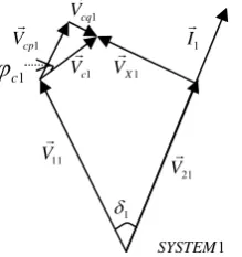
[image:3.595.94.258.52.458.2]Fig.5. Phasor diagram of IPFC for system1
Fig.6 shows the simplified Fig.5 based on equation (12). In Fig 6 it can be seen that phasor of line current in system1 (
I
1)has a real part only (vector).
Fig.6. Phasor diagram of IPFC for system 1 after change
Line current I1 with only real part in Equation (12) shows values of
Q
r1 reactive power flow at receiving end and IPFC injected reactive power is zero. Under this condition, the injected complex power by IPFC in system 1 is a function with respect to the real vector of the injected IPFC voltage and real vector of line current. Thus,p cq p cp q cp p cq q cq p cp q p cq cp c c c c
I
jV
I
V
I
V
I
V
j
I
V
I
V
jI
I
jV
V
I
V
jQ
P
S
1 1 1 1 1 1 1 1 1 1 1 1 1 1 1 1 1 1 1 1 1)
(
)
)(
(
From equations (12),
(13) Qr
V
cpI
p1 1 0 1
21 1 1 11 211
(
cos
)
V
P
V
V
P
r c
(14) ( cos )
1 11 21
1
1 V
V P
P r
r (15)
V
11cos
1
V
21
V
cp1
From equations (8), (13), (14) and (15),
(16)
21 ) 1 ( 1 1 1 1 1 11 1
1
sin
sin
c
c cp cp cX
V
V
X
V
V
P
[image:3.595.308.488.56.214.2]In this context, phasor diagram of system 1 in Fig. 6 is simplified as shown in Fig. 7.
[image:3.595.354.449.246.356.2]Fig .7. Phasor diagram of system1
Fig.7 shows that line current phasor of system1 (
I
1) has only real vector and I1 is in the same phase with V21 as receiving end voltage in system 1. In Fig.8, it is apparent that for system 2 phase angle, phase angle between I2 & Vcp2 is 180°
because system 2 balances the needed active power for system 1.Fig.8. Phasor diagram of system 2
The active and reactive power flow equations at receiving end line 2 are
(17) 1
1 11 21 21 1 2
)
cos
(
c c rP
V
V
V
P
P
(18)
22 2
2 2 22 2 2 22 2 2 12 22
2 cos cos c
c r X V V X V X V V Q where 22 22 22V
V ,
V
12
V
12
12
,
V
c2
V
c2
c2
12 22
2
V
,
V
For this case, the characteristics of IPFC for system 2 can also be considered as SSSC. For (18) it is shown that
(19) )
2 cos( cos 2 2 2 22 2 2 22 2 2 12 22 2
c c
[image:3.595.308.463.456.562.2] [image:3.595.123.233.512.629.2]b. Capacitive mode of IPFC
Principal privilege of IPFC in this mode emerged to improve the aforesaid problems of SSSC. In this way, it provides simultaneous and independent compensation of needed reactive and active power in system 1 by system 2. It can lead system 1 to the maximum active power transfer ability and control the reactive power flow in system1. Thus, the maximum injected active power IPFC in system1 is cal-culated by the derivative of equation (8) with respect to
φc1
,
1 21 1 1 21
1 cos
sin
c cos
c sin
cr c
X V V P
0
)
sin
sin
cos
(cos
0
21 1 21 11
1
c c
c c
d
dp
(20) 1 21
2
cSince the maximum sending active power to end line for system can be calculated by substituting
φc1
= (π/2) –φ21
in (8),(21)
1 1 21 1 1
21 11
1
sin
X
V
V
X
V
V
P
cr
Q
r1 is found from equation (9).Therefore, the capacitive mode can be used to solve the problem of increasing and decreasing reactive and active power in transmission line with high X/R ratio respectively. This is because capacitive mode region of system 1 is between 0 to π/2 and system 2 supplies the needed active power of system1. The capacitive mode region of system 2 is between π/2 to π. Thus, system 2 is formulated as
(22)
2 22
2 2 22 2 2
12 22
2
sin
cos
c
cr
X
V
V
X
V
V
P
(23)
22 2
2 2 22 2 2 22 2 2
12 22
2 cos sin c
c r
X V V
X V
X V V
Q
c. Inductive mode of IPFC
In some conditions, an inductive mode of IPFC is used to approach to the minimum value of the injected active power and decreases the injected reactive in system 1 simultaneously. This indicates that
r1 c1T
P
P
P
(
)
)
(
P
TMIN
P
r1P
c1MIN
(24) 0
2 ) (
)
(PT Pr1Pc1 c1
MIN
where
P
T is sending active power to end line.Therefore equations (8), (9) and (24) can be used to find the sending active and reactive power to end line in system1. The operation region of IPFC in system 1 is between -π/2 and to 0. Due to the system 2 that supplies system1 active power demanding, the capacitive region of system 2 tends to between -π/2 to - π. For system 2,
(25)
)
2 sin(
sin 2 22
2 2 22 2 2
12 22 2
c
c r
X V V X
V V
P
Thus, reactive power flow is similar to capacitive mode.
Case study
The proposed method has been tested on two machine system as same as IPFC in Fig.3[10]. The simulation is based on resistive, capacitive and inductive modes. The buses of two systems have been assumed ideal (infinitive bus). The voltage of two system generators are 1 P.U. with a 30° and line reactance of 0.5 P.U.
a. Resistive mode
In this case, the voltage phasor, Vc1with a magnitude of
0.134 P.U is injected at –30°. [Pr1 , Qr1]ischanged from [1.0,
- 0.2681] P.U to [1.0, 0] P.U. [Pr2 , Qr2] leads to [0.866, -0.53]
[image:4.595.300.552.123.198.2]P.U from [1.0, -0.2681] P.U. Therefore, equations (8), (9), (17), (18) and (19) are used for numeral estimation. Results of resistive mode are shown in Table1.
Table.1. Reactive and reactive power flow estimation of system 1, 2 (p.u) in resistive mode
Resistive
Mode Simulation Proposed method %Error
Pr1 1.000191 0.02
Qr1 0 0 0
Pr2
0.866 0.86619 0.021
Qr2
-0.53 -0.5356 1.45
b. Capacitive mode
For capacitive mode, a voltage phasor Vc1with a magni-tude of 0.26 P.U is injected at +45°. The values of [Pr1 ,
Qr1], with an ideal lossless system is changed to [1.5,
-0.1341] P.U. The values of [Pr2,Qr2]is keptat [0.866, -0.53]
P.U. For estimation of this mode, equations (8), (9) ,(21), (22), (23) are applied. The results are shown in Table 2. Table.2. Active and reactive power flow estimation of systems 1 and 2 (p.u) in capacitive mode
Capacitive
Mode Simulation
Proposed
method %Error Pr1
1.5 1.52 1.35
Qr1
-0.134 -0.1336 0.3
Pr2
0.866 0.8654 0.069
Qr2
-0.53 -0.527 0.569
c. Inductive mode
A voltage phasor Vc1 with a magnitude of 0.26 P.U is
injected at -75. The values of [P
r1 , Qr1] is changed to
[0.634, 0.0981] P.U as the same as the capacitive mode. [Pr2 , Qr2] remains at[0.866, -0.53] P.U. (8), (9) (23) and
[image:4.595.300.549.438.673.2](25) are used for this case and the results are shown in Table 3.
Table.3. Active and reactive power flow estimation of systems 1and 2 (p.u) in inductive mode
Inductive
Mode Simulation
Proposed
method %Error Pr1
0.6320.634 0.315
Qr1
0.0990.098 1.01
Pr2
0.866 0.8654 0.069
Qr2
-0.53 -0.5276 0.569
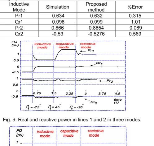
Fig. 9. Real and reactive power in lines 1 and 2 in three modes.
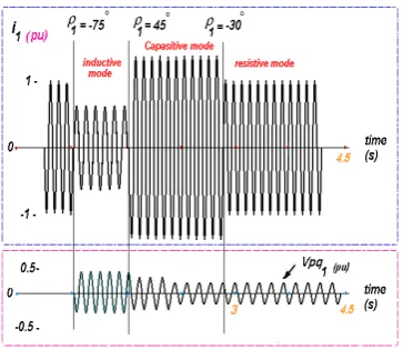
Fig .11. Waveforms of line current and injective voltage of IPFC in three modes.
[image:5.595.76.263.336.442.2]The simulation of these modes was carried out by power system analysis tools package in MATLAB software and is depicted in Fig.9. Fig.10 shows the VSI injecting complex power of IPFC in three modes for system 1. Also, system1 line current and series injecting voltage of VSI in system 1 have been simulated as shown in Figs. 10 and 11. The operating points of IPFC for two systems can be illustrated in Fig 12.
Fig .12. Operating points of IPFC for two systems.
Conclusions
In this paper, the characteristics of SSSC and IPFC based on new injection model were considered. Firstly, a linear model of voltage source inverter (VSI) of IPFC was improved. Therefore, robust equations of the active and reactive power of IPFC based on new injection model were used. The estimation of the initial injected voltage and its phase angle of IPFC and SSSC for their modelling was done in practical manner. This model was tested in inductive, capacitive and resistive modes of IEEE two machine systems. The comparison of the results with MATLAB simulation shows that the proposed method in different operating point of IPFC is acceptable. In addition, this method can be extended to acquire the approximation of active and reactive power flow of receiving end line equations with transmission line resistance.
Acknowledgment
This work was supported by the Malaysian Government and University of Malaya, under postgraduate research grant PPP (Grant NO:PS009-2012A)
REFERENCES
[1] L. Gyugyi, "Dynamic compensation of AC transmission lines by solid-state synchronous voltage sources," Power Delivery, IEEE Transactions on, vol. 9, pp. 904-911, 1994.
[2] L. Gyugyi, et al., "Static synchronous series compensator: a solid-state approach to the series compensation of
transmission lines," Power Delivery, IEEE Transactions on, vol. 12, pp. 406-417, 1997.
[3] K. K. Sen, "SSSC-static synchronous series compensator: theory, modeling, and application," Power Delivery, IEEE Transactions on, vol. 13, pp. 241-246, 1998.
[4] L. Gyugyi, et al., "The interline power flow controller concept: a new approach to power flow management in transmission systems," Power Delivery, IEEE Transactions on, vol. 14, pp. 1115-1123, 1999.
[5] L. Gyugyi, et al., "The unified power flow controller: a new approach to power transmission control," Power Delivery, IEEE Transactions on, vol. 10, pp. 1085-1097, 1995.
[6] K. K. Sen and E. J. Stacey, "UPFC-unified power flow controller: theory, modeling, and applications," Power Delivery, IEEE Transactions on, vol. 13, pp. 1453-1460, 1998.
[7] S. Jiang, et al., "Damping performance analysis of IPFC and UPFC controllers using validated small-signal models," Power Delivery, IEEE Transactions on, vol. 26, pp. 446-454, 2011. [8] X. Jiang, et al., "Transfer path stability enhancement by
voltage-sourced converter-based FACTS controllers," Power Delivery, IEEE Transactions on, vol. 25, pp. 1019-1025, 2010. [9] V. Diez-Valencia, et al., "Interline power flow controller (IPFC)
steady state operation," in Electrical and Computer Engineering, 2002. IEEE CCECE 2002. Canadian Conference on, 2002, pp. 280-284.
[10] N. G. Hingorani, et al., Understanding FACTS: concepts and technology of flexible AC transmission systems vol. 1: IEEE press New York, 2000.
[11] R. Strzelecki, et al., "Interline power flow controller-probabilistic approach," in Power Electronics Specialists Conference, 2002. pesc 02. 2002 IEEE 33rd Annual, 2002, pp. 1037-1042. [12] R. Strzelecki, et al., "Interline power flow controller-properties
and control strategy in dynamic states," in Compatibility in Power Electronics, 2005. IEEE, 2005, pp. 11-17.
[13] M. KARIMI, et al., "Distribution State Estimation Incorporating Load Modelling," PRZEGLAD ELEKTROTECHNICZNY, vol. 88, pp. 166-169.
[14] P. Kundur, et al., "Overview on definition and classification of power system stability," in Quality and Security of Electric Power Delivery Systems, 2003. CIGRE/PES 2003. CIGRE/IEEE PES International Symposium, 2003, pp. 1-4. [15] A. de la Villa Jaén, et al., "Voltage source converter modeling
for power system state estimation: STATCOM and VSC-HVDC," Power Systems, IEEE Transactions on, vol. 23, pp. 1552-1559, 2008.
[16] B. Renz, et al., "AEP unified power flow controller performance," Power Delivery, IEEE Transactions on, vol. 14, pp. 1374-1381, 1999.
[17] R. L. Vasquez-Arnez and L. C. Zanetta, "A novel approach for modeling the steady-state VSC-based multiline FACTS controllers and their operational constraints," Power Delivery, IEEE Transactions on, vol. 23, pp. 457-464, 2008.
[18] J. Chen, et al., "Basic control of interline power flow controller," in Power Engineering Society Winter Meeting, 2002. IEEE, 2002, pp. 521-525.
[19] B. K. Johnson, "How series and combined multiterminal controllers FACTS controllers function in an AC transmission system," in Power Engineering Society General Meeting, 2004. IEEE, 2004, pp. 1265-1267.
[20] S. Bhowmick, et al., "An advanced IPFC model to reuse Newton power flow codes," Power Systems, IEEE Transactions on, vol. 24, pp. 525-532, 2009.
[21] J. Hu, et al., "Direct active and reactive power regulation of grid-connected DC/AC converters using sliding mode control approach," Power Electronics, IEEE Transactions on, vol. 26, pp. 210-222, 2011.
Authors: Amidaddin Shahriari,University of Malaya, Kuala Lumpur, E-mail: [email protected]. Dr. Hazlie Mokhlis, University of Malaya, Kuala Lumpur, E-mail: [email protected]. Dr. Ab Halim Abu Bakar, University of Malaya, Kuala Lumpur, E-mail: [email protected]. Mazaher Karimi, University of Malaya, Kuala Lumpur, 59200, E-mail: [email protected]. Dr. Hazlee A. Illias, University of Malaya, Kuala Lumpur, 59200, E-mail: [email protected].