5
IX
September 2017
Improvement Of Power Quality Using Photovoltaic
Dynamic Voltage Restorer
Saliha Aarif1, Er. Ravinder Kaur Randhawa2
1
P.G. Student, Department of Electrical engineering, Guru Nanak Dev Engineering College, Punjab, India
2
Assistant Professor, Department of Electrical engineering, Guru Nanak Dev Engineering College, Punjab, India
Abstract: In today’s scenario the power quality has become one of the major requirements in the power system where electricity is concern. The power quality problems are generally produced by power electronics equipment’s. These equipment’s may produce nonlinear loads. These can produce interruption in power system hence produce power quality problems. Some of the power quality problems are voltage sag, voltage swell, transients, harmonics, voltage spikes etc. Among this voltage sag is one of the major power quality problems. It has detrimental effect on the system operation. In this way, there is a need to compensate it in order to avoid perturbation in the system. For this a Custom Power Device is used namely ‘Photovoltaic Dynamic Voltage Restore’. Photovoltaic system used with dynamic voltage restorer can help for energy storage for battery system for further operation. It is non-conventional source of energy. So, it is cheaper. A three-phase source is connected with dynamic voltage restorer and photovoltaic system to have better results in the mitigation of voltage sag. The results under three-phase fault condition and the output waveform of Photovoltaic systems under MPPT control can be obtained using MATLAB/Simulink. Keywords: Photovoltaic Dynamic Voltaic Restorer; Voltage Sag; Maximum Power Point Tracking; Three-phase source
I.INTRODUCTION
The power system consists of generation, transmission and distribution systems. In generation system, enormous power is generated with the system that is used to generate power. In transmission system, the power that is generated through generating unit is transmitted by wires to long distances while transferring the power, perturbation occurs due to abnormal conditions of circuit. Thus, this power is distributed by distribution system. Distribution system is essential where power quality interruptions concern. [1] This is because there is a direct connection between customer or distribution system in regards of power. So, the distribution system is the major area of concern. As it is concerned already that power quality is the essential part for the electricity consumption customers and it is also important for the utility that is providing us electricity. so it is require concentrating on the improvement of the quality of power so that reliability can be improved. In order to enhancement of power quality there is a need of some power quality improvement alternative that provides us better solution. One of the major solutions to power quality problems are use of compensating type devices which comes under Custom Power Devices. All compensating type devices have their own benefits and drawbacks. But DVR (Dynamic Voltage Restorer) is chosen because of its advantages over other devices. [11]DVR has merit over UPS (Uninterrupted Power Supply) like low cost, high efficiency, low losses and less maintenance. That’s why DVR is utilized instead of UPS. DVR is preferred in place of DSTATCOM (Distribution Static Compensator) because of its (DVR) small size in comparison to DSTATCOM. Otherwise DSTATCOM can also use. Basically, DSTATCOM is similar to STATCOM as both follow the same principle. SVC (Static Var Compensator) antedates the DVR but still DVR prefers more due its capability is more as compared to DVR and also DVR has ability to control active power flow. This is the reason we utilize DVR (Dynamic Voltage Restorer) over other compensating devices. Therefore, the scope of thesis is on the application of Dynamic Voltage Restorer and evaluation of DVR with its components, controlling and detecting techniques. [11]. That’s the reason for choosing DVR over other custom power devices as it has more benefits over other compensating type devices.
II. PHOTOVOLTAIC BASED DYNAMIC VOLTAGE RESTORER
for exploration. As there are variety of generation sources i.e. DC. Three-phase etc. there is a need to combine these types of power generators in a common transmission line, hence PV and three phase generation units has been considered to combine by DVR to get the load power.
III.BASICDYNAMICVOLTAGERESTORER
[image:3.612.199.419.212.366.2]Dynamic voltage restorer (DVR) is a series compensating device. It is used to inject voltage in series in order to balance the voltage in the system. DVR is used not only for compensating the voltage but also used to detect the faults in the system and to control it to enter into the system. DVR consists of injection transformer, filter, voltage source converter, energy storage devices and control system are shown in Fig. 1
Fig 1. Basic DVR with its Component
There are different methodologies for compensating the voltage magnitude and also there are some techniques used for detection the fault in the system. Controlling techniques are also used to control the imperfections i.e. power quality problems in the system
A. DVR Modelling
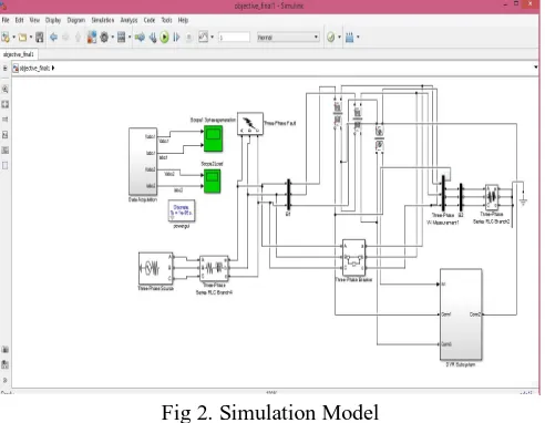
The hybrid model is made using phase source, PV & DVR system. DVR is located in between source and load. For that three-phase source is taken and static load is considered in the system between these DVR is located. Fig. 2 shows the block diagram of three-phase generation system, PV & DVR system.
Fig 2. Simulation Model
[image:3.612.184.430.501.692.2]branch. Here only RL branch is considered as only DS or short wire is considered. RLC branch is considered only when transmission or long-distance wire is considered. A source branch B1 is taken over which three-phase fault is connected. Due to this a voltage distraction occurred in the system because of that system voltage goes decreases from its nominal value. This voltage disturbance is known as voltage sag. This is shown in slope 1 and is compensated by DVR the results.
Table 1. shows the parameters which are considered during modelling of whole system that consists of three-phase source of 50 Hz frequency and resistance is of 0.1Ὡ. Source impedance that include resistance of 0.001 Ὡ and inductance of 0.005 H. here capacitance i.e. C is neglected as DVR dealing with DS only. Static load is taken with constant R & L. the value of voltage and current has been measured at source, load side and DVR side.
TABLEI
SYSTEMPARAMETERSFORANALYSIS
Two winding injection transformers is connected in the system which is used for coupling the balanced and unbalanced system. Primary winding is connected with unbalanced system and secondary winding is connected with DVR which is used for the compensation process. Same side static load is connected which is also being affected by three-phase fault. The simulation model of DVR is shown in Fig. 2 is made using MATLAB R2016a/SIMULINK.
IV.PHOTOVOLTAICSYSTEM
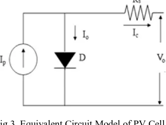
Photovoltaic systems include PV array system which consists of two or more solar panel that converts sun light into electricity. Photovoltaic system is a non-conventional source of energy like wind turbine etc. It is used with DVR system for energy storage. This system will provide energy to dc source which is used by inverter system to convert dc energy into ac energy for further applications of DVR system. The Equivalent circuit model of photovoltaic cell is shown in Figure 3.
Fig 3. Equivalent Circuit Model of PV Cell
The Photo Voltaic model is created using basic equations of photovoltaic cells including the effects of temperature changes and irradiation. The photovoltaic equation is shown in equation No.1
VC=AKTC/e*ln(IPh+IO-IC/IO)-RSIC (1) Where,
Vc is cell output voltage in volts. A: fitting factor.
Sr No. System quantities Standards
1 Source Three-phase, 50 Hz, 0.1Ὡ
2 Source Resistance and Inductance 0.001Ὡ, 0.005 H
3 Fault Resistance and Switching time 0.01Ὡ ,0.2 to 0.4
4 Load Resistance and Inductance 1Ὡ ,1H
E: electron charge. Iph : Photo current (10 A).
Io is reverse saturation current of diode (0.0002 A). k is Boltzmann constant (1.38 *10 - 22 J/0k). Ic :cell output current in A.
Rs is solar cell internal resistance (0.001 Ω).
Tc: operating temperature of the reference cell (400c).
A. Photovoltaic Modelling
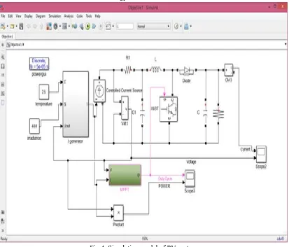
[image:5.612.101.514.245.598.2]Photovoltaic system is considered and is modelled by using Simulink. As shown in Figure 4. The photovoltaic system or cell is used as a nonconventional source of energy. The photovoltaic system or cell is used as a nonconventional source of energy. This cell is connected with Dynamic Voltage Restorer. Photovoltaic system is considered and is modelled by using Simulink. The photovoltaic system or cell is used as a nonconventional source of energy.
Fig 4. Simulation model of PV system
TABLEII
PARAMETERSOFPVSYSTEM
Table 2 shows that the parameters of PV cell. Which are considered in thesis work. It is observed that temperature and irradiance are taken 250c and 800 W/m2 respectively. In source impedance, i.e. RLC branch Resistance and Inductance are 1 Ὡ and 0.01 H respectively. Insulator Gate Bipolar Transistor is taken as a universal bridge. Whose resistance and voltage are taken as 0.001Ὡ and 1V. Similarly, diode resistance and inductance are taken as 0.001 Ὡ and 0.8V respectively.
V. RESULTS AND DISCUSSIONS
In this thesis work, to prove the effectiveness of PV based DVR for power quality problems like voltage sag, voltage swell, harmonics etc. on distribution system. The DVR is modelled using MATLAB/SIMULINK to compensate faults on the system. Three phase faults are compensated at source side. The purpose of DVR is to improve power quality on distribution system having load. The voltage sag, voltage swell occurs due to fault on the system.
A. Voltage Sag Compensation Using Dvr
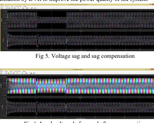
The three phase fault conditions are considered in the test system. The faults can cause power quality interruptions in the system mainly voltage sag. As voltage sag is predominant found in the system and have severe impact so it needs to compensate this and this work is done by DVR. Fig 5. shows that the voltage is balanced between time 0 to 0.2 sec. but due the 3-phase fault voltage is decreased from 0.2 sec to 0.4 sec. This decreased voltage is known as voltage sag is shown in the Fig 5.
[image:6.612.115.497.108.231.2]Fig5.also shows the voltage compensation by DVR to improve the power quality of the system.
Fig 5. Voltage sag and sag compensation
Fig 6. Load voltage before and after compensation
Fig 6. Shows the load voltage also affected by the occurrence of 3-phase fault in the system from the same switching time. The switching time of fault is 0.2 sec to 0.4 sec. It means that voltage sag occurs between these times as shown in the Fig 6 and this voltage sag is compensated by using DVR. Similarly load voltage is also compensated by DVR.
Sr No. System quantities Standards
1 Temperature 250c
2 Irradiance 800 W/m2
3 Source Impedance R=1Ὡ, L= 0.01 H
4 IGBT Resistance and Voltgae 0.001Ὡ ,1V
[image:6.612.177.432.468.672.2]B. Results Under Photovoltaic System
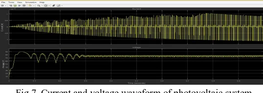
[image:7.612.169.438.159.254.2]Fig 7 shows that the current and voltage waveform of Photovoltaic system. Here it is shown that after the Maximum Power Point Tracking control the value of current is increasing from zero to its maximum point for providing energy to dc source. The supply voltage waveform initially is being interrupted from 0 to 0.3 sec and after maximum power point tacking it is becoming smooth slowly from 0.3 sec to 0.9 sec. Fig 7. shows that the supply voltage waveform initially is being interrupted from 0 to 0.3sec and after maximum power point tacking it is becoming smooth slowly from 0.3sec to 0.9 sec.
Fig 7. Current and voltage waveform of photovoltaic system
[image:7.612.185.429.303.391.2]After maximum power point tracking gate pulses output and power by MPPT control for Insulated Gate Bipolar Transistor control is shown in fig 8.
Fig.8 Gate pulses output and Power by MPPT control
These waveforms show the results of Photovoltaic system. Duty cycle is the fraction of period in which a system is being active. Duty cycle is expressed in percentage or ratio.
VI. CONCLUSION
A compensating type device is used to compensate voltage sag. This device name is Dynamic Voltage Restorer. This device is used with Photovoltaic system. PV cell acts as an energy storage device just like capacitor. It gives its energy to dc source i.e. battery. From this inverter system is run with its components mainly universal bridge. A hybrid model of three phase generation system, photovoltaic system and dynamic voltage restorer is made using MATLAB/SIMULINK. The results are taken from this power tool system under three phase fault conditions. Most probably voltage sag has much chance to occur in the system. So, in this research work voltage sag and also load side voltage is being compensated by using Dynamic Voltage Restorer (DVR).
REFERENCES
[1] Abijeet G, S. and Kumar S, P.(2014)” Enhancement of Power Quality Problem by Using Dynamic Voltage Restorer” 2014 International Journal of Innovative Research in Advanced Engineering (IJIRAE) ISSN: 2349-2163 Volume 1 Issue 6
[2] AlMathnani,A.O., Mohamed,A.and Ali,M.A.M.(2007)“Photovoltaic Based Dynamic Voltage Restorer For Voltage Sag Mitigation” 2007 5th Student Conference on Research and Development, IEEE Conference Publications 2007, pp: 1 – 6
[3] AppalaNaidu,T.(2016)“ The Role Of Dynamic Voltage Restorer (DVR)in improving power quality” 2016 2nd International Conference on Advances in Electrical, Electronics, Information, Communication and Bio-Informatics (AEEICB) ,pp: 136 – 141
[4] Babu,.PS.and Kamaraj,K(2013)“Performance investigation of dynamic voltage restorer using PI and fuzzy controller” 2013 International Conference on Power, Energy and Control (ICPEC), pp: 467 – 472
[5] Deepika,S.,Saranya,M.andPoorani,V(2015)“PI controller based dynamic SAG compensator with PV PANEL: PIcontroller based DVR”2015 International Conference on Advanced Computing and Communication Systems, pp:1 – 6