2018 International Conference on Modeling, Simulation and Analysis (ICMSA 2018) ISBN: 978-1-60595-544-5
Study on the Liquid Metal Flow Field in Narrow-Side-Patter-Mold
of Slab Continuous Casting
Zhen-qiang ZHANG
*, Jian-bo YU, Jiang WANG and Zhong-ming REN
State Key Laboratory of Advanced Special Steel, Shanghai, China
Shanghai Key Laboratory of Advanced Ferrometallurgy, Shanghai, China
School of Materials Science and Engineering, Shanghai University, Shanghai, China
*Corresponding author
Keywords: Narrow-side-patter-Mold, Electromagnetic brake, Velocity measurement, Continuous casting.
Abstract. The flow pattern and velocity distribution of liquid metal in the Narrow-Side-Patter-Mold (NSP-Mold) have been investigated with a mercury model as analogue to molten steel in the continuous casting. The Ultrasonic Doppler Velocimeter (UDV) has measured the velocity under various magnetic distribution and flux density. The impingement intensity of liquid metal to mold narrow wall have been calculated based on the measured data, and the influence of magnetic flux density on the liquid metal flow in the mold has been analyzed. The results show that with narrow-side-patter magnet and increase of the magnetic field, the surface of the melt gets weak and the free surface fluctuation is suppressed, the impingement intensity of liquid metal to mold narrow wall gets weak, impacting depth becomes shallow and a plug flow can be rapidly formed.
Introduction
Molten steel flow in the continuous casting mold plays an important role in the eliminating of inclusions, entrapment of mold power, uniform growth of initial solidification shell, and the surface and internal quality of slab. With casting speed increasing, the flow rate and kinetic energy of molten steel poured from the SEN greatly increases, resulting in a more complex flow pattern in the mold, and some solidification defects, such as gas bubble and inclusion entrapment and corner crack, etc. will increase. Consequently, the flow control at the mold region has become a research focus and one of key technology 1.
In order to control the flow and improve the quality of continuous casting, electromechanical brake (EMBr), Flow Control Mold (FC-Mold) and FC-Mold II technology has been applied widely now 2-12. By above-mentioned the way of electromagnetic brake, the impingement intensity become more strong, impacting depth becomes deeper. If using upper magnetic field, impacting depth will becomes deeper. In order to suppress the impacting depth, a new way of electromagnetic brake is considered to get better result. The magnets in NSP-Mold consist of two parts, the left electromagnet is installed at left of the mold, and the right one is installed right of the mold.
When the liquid metal flows passes the static magnetic field region, a braking force is generated. The magnet field can suppress the surface fluctuation and brake the flow below the SEN, then the flow pattern and velocity distribution in the mold are optimized, promoting the formation of a plug flow in the mold. Therefore, the solidification defects will be eliminated, and high quality production is realized 13-17.
Experiment
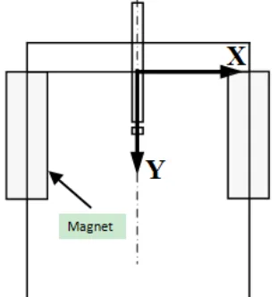
[image:2.595.221.376.179.345.2]The Narrow-Side-Patter of continuous caster mold of a steel mill is built, as shown in Fig.1. The experimental system, as shown Study on the Liquid Metal Flow Field in FC-Mold of Slab Continuous Casting3 in Fig. 1. The cross point of centerline of SEN and the free surface of molten steel is set as coordinate origin and direction of coordinate axis is shown in Fig. 1. The parameters of experimental apparatus and magnetic fields are listed in Table 1. The magnetic flux density in the mold is shown in Fig.2.
[image:2.595.153.445.393.624.2]Figure 1. Schematic of physical simulation experimental apparatus of flow in mold.
Table 1. Magnetic field intensities.
Case Bmax (T)
1 0
2 0.2
3 0.3
x (mm)
y
(mm)
0.1 977
5 0.1 73 25 0.14 875 0.12 425 0.0 99 75 0.0
752 5
0.0507
5
0.03 85
0.0 262
5 0.1 97 75 0.1 855 0.16 1 0.1 365 0.11 2 0.08 75 0.06 3 0.0 38 5 0 .0 2 6 2 5
0 20 40 60 80 100 0 20 40 60 80 100 120 140 150 x (mm) y (mm) 0.28 175 0.2 63 5 0 .2 2 7 0.1 90 5 0.15 4 0.0 99 25 0.0 6 27 5 0.04 45 0.02 625 0 .28 17 5 0 .24 52 5 0 .2 0 8 75 0 .17 2 25 0 .1 3 57 5 0 .08 1 0 .0 44 5 0 .0 2 6 2 5
0 20 40 60 80 100
0 20 40 60 80 100 120 140 150
(a) Bmax=0.2T (b) Bmax=0.3T
Figure 2. Magnetic flux density.
Results and Discussion
Flow Pattern and Velocity Distribution in NSP-Mold
recirculation zone is weakened. It is also shown that increasing the magnetic field leads to decrease the quantity and vertical velocity of flow of liquid metal, the impacting depth becomes shallower. So it is easy to form a plug flow in the mold.
x/mm
y/
m
m
20 40 60 80 100 20 40 60 80 100 120 140 160 180 200 220 -0.1 0 0.1 0.2 0.3 0.4 0.5 0.6 B=0T,H=50mm x/mm y/ m m
20 40 60 80 100 20 40 60 80 100 120 140 160 180 200 220 -0.1 0 0.1 0.2 0.3 0.4 0.5 0.6 B=0.2T,H=50mm x/mm y/ m m
20 40 60 80 100 20 40 60 80 100 120 140 160 180 200 220 -0.1 0 0.1 0.2 0.3 0.4 0.5 0.6 B=0.3T,H=50mm
[image:3.595.130.469.125.311.2](a) B =0T (b) B =0.2T (c) B =0.3T
Figure 3. Velocity distribution in NSP-Mold with various magnetic fields.
Flow Pattern and Velocity Distribution near Free Surface in the NSP-Mold
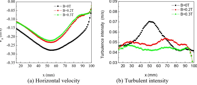
Fig.4 shows the horizontal velocity and turbulent intensity at 30 mm below the free surface. As shown in Fig.4 (a), in the case of B=0T, the maximum horizontal velocity is -0.28 m/s (direction of flow is shown in Fig.1). With the magnetic flux density of magnet at 0.3T, compared with the one at B=0T, the horizontal velocities in most part are smaller, -0.22 m/s. From Fig.4 (b), one can learn that with the magnetic field, the turbulence intensities of the flow near the surface are weaker than that without magnetic field, indicating surface being more stable.
It is indicated that the horizontal velocity near the free surface decreased with B≠0T, which is beneficial to reduce the slag entrainment by vortex near the SEN. In Fig.4 (b), the maximum turbulence intensity generated by the horizontal velocity component at meniscus without magnetic field is 0.08 m/s; as the magnetic flux density increases from 0T to 0.2T and 0.3T, the maximum turbulence intensity at meniscus decrease from 0.08m/s through 0.053 m/s to 0.048 m/s. Therefore, the magnetic field can decrease the maximum turbulence intensity at meniscus, and improve the stability of the surface stream.
20 30 40 50 60 70 80 90 100
-0.35 -0.30 -0.25 -0.20 -0.15 -0.10 -0.05 0.00 B=0T B=0.2T B=0.3T VX (m /s) x (mm)
[image:3.595.128.469.549.697.2]20 30 40 50 60 70 80 90 100 0.03 0.04 0.05 0.06 0.07 0.08 0.09 B=0T B=0.2T B=0.3T Tu rbu le nc e i nte ns ity (m /s ) x (mm) (a) Horizontal velocity (b) Turbulent intensity
Figure 4. Influence of magnetic flux density on the flow at 30 mm below free surface.
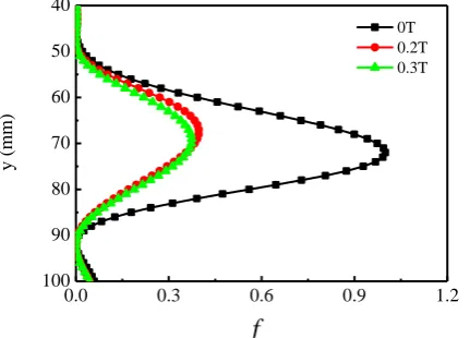
Impacting Intensity on the Mold Narrow Wall in NSP-Mold
intensity is 1, 0.34 and 0.30, respectively. From above calculated data, it is shown that the condition of magnetic field presents that increasing the magnetic flux density leads to decrease of the peak value of impacting intensity. This is beneficial to the generating of initial solidification shell.
100 90 80 70 60 50 40
0.0 0.3 0.6 0.9 1.2
y (m
m
)
f
[image:4.595.193.409.122.277.2]0T 0.2T 0.3T
Figure 5. Influence of magnetic flux density on mold narrow wall.
Conclusions
With the narrow side patter magnets and increasing the magnetic flux density, the flow velocity near free surface is decreased, the fluctuation at meniscus zone is suppressed and the stability of the surface stream is improved. At the same time, scouring intensity in lower recirculation zones is decreased, and the impacting depth becomes shallower. So it leads to be easy to form a plug flow in the mold.
Acknowledgement
This research was financially supported by the National Science Foundation of China (No.51604171, No.51690162, No.U1560202) and Shanghai Science and Technology Commission Grant (No.17JC1400602).
References
[1] A. Idogawa, M. Sugizawa, S. Takeuchi, K. Sorimachi, T. Fujii, Control of molten steel flow in continuous casting mold by two static magnetic fields imposed on whole width, Mat. Sci. & Eng., A173 (1993), 293-297.
[2] Kariya K, Kitano Y, et al,. Development of Flow Control Mold for High Speed Casting Using Static Magnetic fields, Steel-Making Conference Proceedings, 1994, 53-58.
[3] Zhen-Qiang Zhang, Jian-Bo Yu, Zhong-Ming Ren, Kang Deng, Study on the liquid metal flow field in FC-mold of slab continuous casting, Advances in Manufacturing, 2015. Vol.3(3), 212-220.
[4] Zhan Yu, Zhen-Qiang Zhang, Zhong-Ming Ren, Zuosheng Lei, Kang Deng, Study on the Fluid Flow in Slab Continuous Casting Mold with Electromagnetic Brake, Acta Metallurgica Sinica, 2010, Vol.46 (10), 1275-1280.
[5] Hao Jia, Zhen-qiang Zhang, Tong-xu Chang, Kang Deng, Zhong-ming Ren, Influence of EMBr on Flow Field of Molten Steel in a Continuous Casting Slab Mold, Chinese Journal of Process Engineering, 2012, Vol.12(04), 550-557.
[7] Hao Jia, Zhen-qiang Zhang, Ji-wen Wu, Tong-xu Chang, Kang Deng, Zhong-Ming Ren, Study on Flow Field of Molten Steel in Slab Continuous Casting Mold with EMBr, Chinese Journal of Process Engineering, 2012, Vol.12(05), 721-726.
[8] Hao Jia, Min Wang, Zhang Zhenqiang, Kang Deng, Zuosheng Lei, Zhong-Ming Ren, Effects of Nozzle Submerged Depth and Casting Velocity on Liquid Metal Flow with EMBr in Continuous Casting of Slab, Shanghai Metals, 2012, Vol.34(1), 53-62.
[9] Tong-xu Chang, Hao Jia, Zhen-qiang Zhang, Kang Deng, Zhong-Ming Ren, Numerical and Physical Simulation on Flow in Mold with EMBr in Continuous Casting of Slab, Journal of Shanghai University, 2013, Vol.19(6), 556-561.
[10] Zhan Yu, Yueming Zhou, Cunyou Wu, Zhen-qiang Zhang, Zhongming Ren, Effect of Electromagnetic Brake on Flow Field in A Continuous Casting Mold and Surface Quality of Slab, Shanghai Metals, 2017, Issue 02, 39-44.
[11] Zhan Yu, Zhen-qiang Zhang, Zhong-Ming Ren. Modeling Study on Electromagnetic Brake for Mold of Slab CCM. Southern Metals. 2017(4), 1-24.
[12] Min Wang, Hao Jia, Zhenqiang Zhang, Kang Deng, Physical Simulation To Liquid Metal Flow with EMBr in Continuous Casting of Slab, Shanghai Metals, 2011, Vol.33(6), 41-60.
[13] Yun-Seong Hwang, Pil-Ryung Cha, Ho-Se Oknam, et al, Numerical Analysis of the Influence of Operational Parameters on the Fluid Flow and Meniscus Shape in Slab Caster with EMBr, ISIJ International, 37(1997), 659-667.
[14] Lehman A F, Tallback G R and Rollberg S G, Fluid Flow Control in Continuous Casting using various configurations of static Magnetic Fields, The 1st International Symposium on Electromagnetic Processing of Materials, Nagoya, ISIJ, 1994, 372-397.
[15] Nagai J., Suzuki K. I., Kojima S, Steel Flow Control in a High-speed Continuous Slab Using an Electromagnetic Brake, Iron and Steel Engineer, 61 (1984), 41-47.
[16] Hanada H. et al., Effect of Density Difference of Molten Steels on the Mixing in Strand Pool in the Sequential Casting of Different Steel Grades with a Level DC Magnetic Field, CAMP-ISIJ, 12 (1999), 830-842.
[17] M. Zeze, H. Tanaka, E. Takeuchi, S. Mizoguchi, Continuous casting of clad steel slab with level magnetic field brake, Steel-Making Conference Proceedings, 1996, 225-230.