Systems Reference Library
FARGO
for
IBM 1401
FARGO (Fourteen-a-One Automatic Report Generating Operation) is a report generator that requires no expert knowledge of programming techniques. This manual explains the writing of report specifications and the preparation of FARGO control cards to produce the desired results. Reports can be prepared on blank paper or preprinted report forms. The method requires a minimum of 4,000 positions of core storage and is applicable to card input files only.
For a list of associated publications and abstracts, see the
IBM 1401 and 1460 Bibliography, A24-1495.
Fourth Edition
This is a reprint of C24-1464-2 incorporating changes released in the following Technical Newsletter:
Form Number Pages Affected
N24-0231 10, 11, 14 July 24, 1964
Significant changes or additions to the specifications contained in this publication will be reported in subsequent revisions or Technical Newsletters.
Contents
Introduction ... 5
General Description 6 Report Specifications ... ... 6
Coding Sheets ... ... 8
Phase 4 (F:orm No. X24-6SS6) ... "... 8
Report-Heading Control Cards ... ... ... ... ... ... 8
Field-Headings Control Cards ... "... 8
Phase 1 (Form No. X24-6SS6) ... 10
~1aster-Report Control Card ... 10
Control-Break Control Cards ... 10
Phase 1 (form No. X24-6SS7) ... ... ... ... 11
Constants Control Cards .... ... 11
Phase 3 (Form No. X24-6SS9) ... 11
Detail Control Cards ... 11
Phase 2 (Form No. X24-6SS8) ... 13
Total Control Cards ... ... ... ... ... ... ... ... 13
Automatic-Carriage-Control Operation ... 15
Operating Instructions ... 16
Program Halts ... 16
Patching ... 17
Multiply-Divide Optional Feature ... 20
I\1ultiplication ... 20
Division ... 22
Half-Adjustments of Products and Quotients ... 26
FARGO General Program Operation and 1401 Core-Storage Organization ... 30
FARGO Report Examples ... ... 31
Register of Earnings and Deductions ... 31
Remittance Statement and Voucher Check ... 31
FARGO, Fourteen-O-One Automatic Report Generat-ing Operation, is a report generator that requires no expert knowledge of programming techniques. It is easy to learn and apply. Developed for the IBM 1401
Data Processing System, F ARGO may be quickly adapted to many types of listed reports or group-printed reports now prepared with unit-record equip-ment on blank paper or on preprinted forms.
In addition to providing the program for processing the input detail-data cards, FARGO provides for printing one title line, including page number, on each page of the report. It also provides for printing two lines of field headings used to designate the various columns of the report. The printing of this information, normally required when preparing reports on blank paper, is controlled by the carriage tape. One advan-tage of FARGO is that any number of different reports may be prepared in a continuous mode, provided the reports are prepared on blank paper and that the carriage-tape specifications are standardized for all the reports.
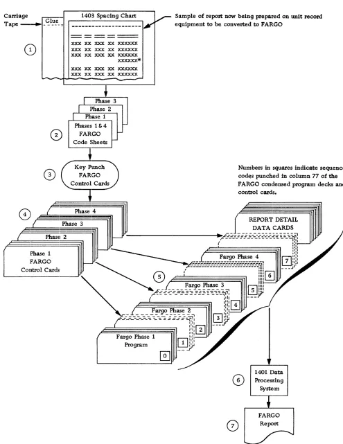
Requirements of the report, such as title and field headings, detail and/or total printing, carriage spacing, skipping, ejecting, etc., are first laid out on an IBM
1403 Printer Spacing Chart. The report specifications are then recorded on specially-designed FARGO
con-Fargo
trol card coding-sheets (Phases 1, 2, 3 and 4). Control cards for each of the four phases are then punched on standard 50B1-type cards. These are inserted behind their respective F ARGO condensed-program decks, and all precede the detail data cards to be processed. The file is then loaded into the 1402 file feed. The operation is started by pressing the load key. The 1401 loads each phase of the FARGO program, and generates the program steps from the control cards that follow each phase.
In approximately 20 seconds, report printing is started. It continues without interruption until the report is finished. This procedure is graphically illus-trated in Figure 1. If several reports are to be run consecutively, a separator card containing a lozenge
(0 , 12-4-B) punch in card column one is placed be-hind the last detail data card for each report. This branches the generated program into the last card routine, ejects to the first printing line of the next form, and immediately begins reading-in the next pro-gram deck.
FARGO is designed primarily for IBM 1401 card
General Description
Following is a list of operations that can be performed under FARGO control.
Print one full line ( 132 positions) of Report II eading on the first line of each page of the report (carriage-tape channel-I, including page numbers.
Skip to carriage-tape channel-2 and print a maxi-mum of two full lines of columnar- or field-headings on each page of the report.
Skip to the body line of the report (carriage-tape channel-3).
List or group-print the body of the report.
Control on a maximum of four fields anywhere in the detailed data cards regardless of length.
Group-indicate a maximum of four fields on the first line of each minor control group.
Distinguish a maximum of 10 different types of de-tail cards and print results in the appropriate columns of the report. Each code used to identify a given type of card may be punched in the same column of the detail card, or a separate column may be used to identify each type up to a maximum of 10. If more than one card-column must be tested to identify a given type of card (multiple column type), a patching rou-tine is generally required. Special provisions have been made within the FARGO program for accomplishing this type of patching. (See Patching.) However, two columns may be tested without patching if, as is fre-quently the case, a type of card is identified by a digit (1-9) in one column and a zone (usually an X) in an-other column. Example: 3 in column 6, X in column 80. (See Figure 25.)
Add, subtract, multiply, and divide detail data or totals.
Accumulate and print totals (with or without sum-mary punching) for each control level, plus final totals at the end of the report. Minor totals are rolled into intermediate totals, intermediate totals into major, etc.
Space before or after printing, or skip to predeter-mined total-lines (carriage-tape channels 4 to 9).
Crossfoot detail data or totals, print the results on desired total levels, and print progressive totals where-ever desired.
Print totals horizontally or vertically for each total level on as many lines as desired.
Print multiple lines from one card (MLP).
Print reports on preprinted forms, including inverted forms with MLP printing. In such cases, specifications for report and field headings are not required.
Card count by types of cards and print card count totals on desired total levels.
Overflow or eject from form to form.
Print any number of different types of reports consecutively, provided that reports are prepared on continuous blank paper and that the carriage-tape specifications are standardized for all the reports.
Report Specifications
Carriage r--:::-:---Glue Tape - ____ - -'--_.';"
1403 Spacing Chart
V-
Sample of report now being prepared on unit record---I..r'
equipment to be, converted to FARGO0)
----eD
(2)
---xxx xx ---xxx xx ---xxx---xxx xxx xx xxx xx xxxxxx xxx xx xxx xx xxxxxx xxxxxx* xxx xx xxx xx xxxxxx xxx xx xxx xx xxxxxx
-
-
.-+
I
Phase 3I
Phase 2I
Phase 1 Phases 1 &4r-FARGO I
-Code Sheets
f-~.
Key~
FARGO Control Cards+
G)
L
Phase 4( Phase 3
( Phase 2
Phase 1
J-FARGO Control Cards
I
[image:7.612.69.564.65.706.2]-/
Figure 1. F ARGO--Basic Steps
@]
Numbers in squares indicate sequence
cod~s punched in column 77 of the FARGO condensed program decks and control cards.
REPORT DETAIL DATA CARDS
1401 Data
I
CD
ProcessingSystem
FARGO
Coding Sheets
Coding sheets (Figure 2) are designed to facilitate the recording of specifications in the FARGO language, following a few simple rules. The statements used to supply the information are based on the logic of the -107. Thus, any person with sufficient knowledge to develop IBM 407 specifications for a given report can
learn and apply the FARGO language with very little training.
The areas on the coding sheets labeled Report,
Pro-grammed By, Page Nos., and Date are for the con-venience of the programmer, but are not punched in the FARGO control cards. If the programmer assigns a number to the program for identification purposes, the number is entered in the area labeled Program
Identification, 73-76. This number is later punched in each FARGO control card.
Each line of the coding sheets is identified by a pre-printed sequence number in columns 77-80. These se-quence numbers should be punched in the control cards. When the control cards for the four phases are properly inserted behind their respective FARGO condensed-program decks, the sequence numbers must be in ascending order as shown here.
No. of Sequence
Phase Cards Cards Numbers
1 Condensed Program Deck 50 0001-0050
1 Control Cards variable 1000-lxxx
2 Condensed Program Deck 32 2000-2031
2 Control Cards variable 301O-3xxx
3 Condensed Program Deck 33 4000-4032
3 Control Cards variable 501O-5xxx
4 Condensed Program Deck 12 6000-6011
4 Control Cards variable 7001-70xx
The coding sheets for the four phases are described in the order in which they are normally filled out.
FORM NO. x24-6556
Phase 4 - Report-Heading Control Cards (two cards maximum).
Field-Headings Control Cards (four cards maximum).
Phase 1 - Master-Report Control Card (one card maxi-mum).
Control-Break Control Cards (four cards maximum).
FORM NO. x24-6557
Phase 1- Constants Control Cards (50 cards maxi-mum).
FORM NO. x24-6559
Phase 3 - Detail Control Cards (variable)
FORM NO. x24-6558
Phase 2 - Total Control Cards (variable)
Phase 4 (Form No. X24-6556)
Report-Heading Control Cards
Two report-heading control cards (sequence numbers 7001 and 7002) provide a maximum of 132 positions of report-heading information that may be printed at the top of each page of the report (carriage-tape chan-nel-I). Report-heading specifications are entered in col-umns 1-68 as follows:
Card Columns
1 2
3-68
Control Data
H - Report-Heading Control Carel. 1 - First card.
2 - Second card.
Enter report-heading information (66 char-acters maximum for each card). Card 1 prints in positions 1-66, Card 2 prints in positions 67-132.
RULE: If a report heading is required, two cards always must be punched, and HI control card must precede H2 con-trol card. Depending on the length of the report heading and the print positions selected, either HI or H2 control card may be blank in columns 3-68. The report heading may include the word PAGE' anywhere on the line if page numbering is specified.
. If a report heading is not required (preprinted forms), these two control cards are omitted.
Field-Headings Control Cards
Four field-headings control cards (sequence numbers 7011-7014) provide two full 132 positions for field-heading information that may be printed on each page of the report following the report heading (carriage-tape channel-2). Field-headings specifications are en-tered in columns 1-68 as follows:
Card Columns
1 2
3-68
Control Data
F - Field-Heading Control Card. 1 - First Card.
2 - Second Card. 3 - Third Card. 4 - Fourth Card.
Enter field-heading information (66 charac-ters maximum for each card). Cards 1 and 2 print first line of field headings:
Card 1 - print positions 1-66. Card 2 - print positions 67-132.
Cards 3 and 4 print second line of field headings:
Card 3 - print positions 1-66. Card 4 - print positions 67-132.
RULE: If field headings are required, these four cards must enter the machine in ascending sequence. If not required (pre-printed forms), they are omitted.
RULE: Whethcr or not report and/or field headings are speci-fied, a blank card punched with the # (3-8) symbol in column 1 must be the last card in the combined program
deck. In other words, it always precedes the first detail
r--.---______________________ .
______________________
~IBI4 INTfiNAllOHAl IUStNESS MACHINES CORPORATION
FORM X24-6!1i59
Printed In U.S,A. 1731741"IJ REPORT __________________ IBM 1401 DATA PROCESSING SYSTEM PROGRAM IDENTIFICATION PRCIGRAMMEO BY IFARGO REPORT SPECIFICATIONS • Phase 3 DATE
Pave of DETAIL CONTROL CARDS - PHASE 3
A-Add; 5 Subtract @ ;;;: Multlplyl % ;;;: Dly . .
? ;;;: Z.ro Addj I = Z.ro Subt,oct D ;;;: Move Dlg"; Y ;;;: Mtn. ZOMI
M=Mov.
Z=MoveaftdSupp''''z...OI
...
_ConI
I N ...
C""'-
.-,,_1
T. ,IT
..
71 11111 I I I I I I ~lol, 0 ' ULI ' 7 1111 '11' "ISII"II 1125
11 :..1. II 7 11"('1 ... IIII~~II II
ttT~l~li~~~~~~~~~~t~~~~~.~~~~~~~-U~~~~~~~~~~~~~ ______ _____
D -.l..1.
D -.l..1.
D I I
D -.l...l
..1.~
j I
~..1.
LI
~..1.
J.J.. ~_I D I D -.l...l
J...1.. j I
11
J_..L
L l
_U
INTERNATIONAL BUSINESS MACHINES CORPORATION
FORM )12-4·6.558
'rl"~itd in U.S ...
~T ___________________ __
IBM 1401 DATA PROCESSING SYSTEM FARGO REPORT SPECIFICATIONS • Phase 2
PROGRAM IDENTIFICATION
~17i7'17.i
I'I!OGIIAMMED BY DATE Page ~of
t-J
.I 1
T .L
TOTAL CONTROL CARDS·- PHASE 2 l=load edif'Control Word E:...::Edit
ctlKlr
M ::::: MOve (fln,tanl Dolo M = Move S::::Subt,ad
@=:Muhiply
" "'Divide ~;;;: Move and Suppress Zeros I = Move and Suppren Ierot
Summ~Jry Punch Column Split
IB"1 INTERNATI()NAl BUSINESS MACHINES CORPORATION
FORMX2"6!i!i7 Printed in U.S.A.. REPORT ___________________ __ IBM 1401 DATA PROCESSING SYSTEM
FARGO REPORT SPECIFICATIONS • Phase 1
PROGRAM IIlENTIFICATION
PROGRAMMED BY DATE _ Poge_of_
CONSTANTS CONTROL CARDS - PHASE 1
Column 1 C Conltant with a word matk; S Corlltant without a word m.grk Colt.,tnnI2·3 = Size of Con,tant Word
Columnl .. -6 = label to IdentlfyConltantWo,d
Column I 7·72 = field for punching Conltant Word (66 charaete,. mQlllmum)
; No. Label S POI.
Sequlnce 1 2 3 4 15 20 25 3D 3 , · . t O 50 5" 70 7217178 sa
I-++-+-+-I--t ~-L-l1 __ l...L.LbhbdJ....!J~I.~1-"L""U±~L..L1-.lbd~· ~I ±;I ::!:I :;!I;:;!I~I :0;1 ::!:Ll==J~~~~:;!I..:::...LLL~:!::;!:.l:..:!.I=.li~.-l=J...!I~±:1 ::::1 ::!I::!I~",-I c:L::!J..:c.J~L..=.1c:j...!.I_l!.-:..I..=.1 11 I I I 1 I. I I ,J oJ,JQ
IB"': INTERNATIONAL BUSINESS MACHINES CORPORATION IBM 1401 DATA PROCESSING SYSTEM
~--~----REPORT _ _ _ _ _ _ . __ . __ PROGRAM IDENTIFICATION FARGO REPORT SPECIFICATIONS • Phases 4 and 1
PROGRAMMED BY DATE _ _ _ .. _ _ _ _ Poge_ oL ..
I' ~ ·'1· ~:;~3~;;;:;;::;;;:::,;;:"··· ,.7.,32 I·S~'
~ w w U ~ ~ ~ ~ ~ A ~ ~
l! J...1..1.J..LJJ L~U I.LLJ_LLLll.LU . ..1J . .l.-Ll...LLLLL..LLL..LLUI I II I J I I I..lJ.J . ..1.~..1.111 II I I .
'7'
CiI';'t-+-t-I--H .. ~ 12 J..1..1.1 I LLl....l..Ll.l.-LLLLLLLL1..J_LJ..J.._LIJ..JJ lli_LLLlLLLl...LJJ.LLLU.lJ Ll LL I I I I I I I 17101'2 .... ++++-t-t. I I II I I I II I I IJ UJ.I ILJ.J.JLL..UL.LLl...JJ....l-.lL1L.LLl._LLl...J....l . .l_LLU_LLLU I III I I I II I '7Iol'~.
lil.i of.,~J-N~t .. Hu~ct,~i,~fol~MV ~u~T~o1.o~1 '~T 1 Ok~6~ili-t'!'jH'~,J J 1 JLL! ILl I LLJ_LLLLLLLI LLl L~L~l' .<
Control Field Card Coh.
I 1 I I I I Flullevel Control (minor) • 2..1~ .-l~ Second level Control (Intermediate)
.3f-.L.1-_U
.< II II
Third Level Conlrol (molor)
~ER_ REPORT :ONTROL CARD - PHASE 1
CONTROL BREAK CONTROL CARDS PHASE 1
6206 I 5MSP Sequence Number
~~
1 0 0 4
[image:9.621.75.564.88.686.2]Phase 1 (Form No. X24-6556)
Master-Report Control
CardThis card (sequence number 1000), always punched
"AI in column 1, specifies:
l. type of report (list or group-print). 2. page overflow, if desired.
3. page numbering, if desired.
4. positions selected to print the page number any-where on the report-heading line.
5. data to be group-indicated on the first line of each minor control group of a listed report only.
The control data is entered in the various columns of the coding sheet as shown here.
Card
Columns
1 2
3
4
5-7 (from)
8-10 (to)
11
12-14 (from) 15-17 (to)
18-20 (from) 21-23 (to)
24-36
37-49
50-62
C antral Data
M - Master-Report Control Card.
L - List; Blank - Group Print.
o (alpha) - Page overflow to carriage-tape channel-I.
Blank - No page overflow.
P - Page numbering if desired. Blank - No page numbering.
IBM 1403 print positions selected for printing
page number on report-heading line. (From
indicates the left-hand or high-order print position while to indicates the right-hand or units print position.)
First field to be group indicated. M - Move
Z - Move and suppress zeros.
Location of data in detail card to be group-indicated. (From indicates the left-hand or high-order card column, while to indicates the right-hand or units card column.)
IBM 1403 print positions selected for printing
first group-indicated field.
Second field to be group-indicated. Same for-mat as Field 1.
Third field to be group-indicated. Same for-mat as Field 1.
Fourth field to be group-indicated. Same format as Field 1.
RULE: The master-report control card is -always punched, even though it might be blank except for the M in column 1 and the sequence number (1000) in columns 77-80.
Control-Break Control
CardsThese cards (sequence numbers 1001-1004) always punched B in column 1, specify the four control levels
and define the card columns in which the control fields are punched in the detail cards. For a simple listed report with no controls, these cards are omitted. When controls are required, the specifications are recorded in columns 1-8 as follows.
Card
Columns
1
2
3-5 (from)
6-8 (to)
Code
B
1 2 3 4
Split-Control Fields
C antral Data
Control-break control card. First-level control (minor).
Second-level control (intermediate). Third-level control (major).
Fourth-level control. Location of control field.
Normally, information in a given level control, iden-tified by a single card-field heading, is punched in consecutive columns of the card. In some cases, the in-formation may be punched in more than one card field but still in consecutive columns of the card. The va-rious card fields involved may be treated as one-level control merely by specifying the level desired (1, 2, 3, or 4), and the high-order position of the left-most field
(from) and the low-order position of the right-most
field (to).
When a given level control (for example, minor) is
split, that is, represented by two card fields that are not adjacent, one field is specified as minor (code 1)
and the other field as intermediate (code 2). Because
an intermediate control-break forces a minor total-level, all the total operations are specified in Tl (minor level) control cards in Phase 2. A single T2 (intermedi-ate level) control card, coded SPS in columns 52-54, follows. However, no total operations are specified on the intermediate level. For each extra B-control card
Phase 1 (Form No.
X~24-6557)Constants Control Cardl;
These cards, punched C or S in column 1, define the length of each constant word, the label used in the program when referring to the constant, and the char-acters that compose the constant word, with or without a \vord mark. Constant areas of core storage used to accumulate totals must be given a label. A maximum of 50 constants control cards may be used. Any com-bination of characters except PGE may be used as a label. The reason PGE cannot be used is that a 4-position constant area is reserved by the program to permit addressing the page number counter. If page numbering is not required, the counter may be used for other purposes in the program, in which case the counter must be referred to by the PGE label.
Because the number of constants control cards may vary from report to report, complete sequence num-bers are not preprinted on the form. Only the hun-dreds position (column 78) need be entered, using 0 for the first 9 lines, then l'~, 2's, etc., as required to establish sequence. If more than one sheet is needed, skip the first line (sequence no. 1010) on all overflow sheets and continue numbering with the second line (lx20). The same numbering scheme applies to se-quence numbers for Total and Detail Control Cards
recorded on other forms.
Specifications for constants are recorded in columns 1-72 as follows.
Card Columns
1
2-3
4-6
7-72
Control Data
C - Constant with a word mark.
S - Special constant without a word mark. Number of positions in the constant word, including blanks.
Label assigned to identify the constant word when referring to it in the program. Composition of the constant word (66 char-acters maximum).
Blank positions are considered characters.
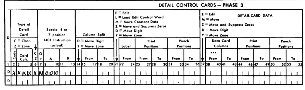
Phase 3 (Form No. X24-6559)
Detail Control Cards
These cards, always punched D in column 1, specify the various operations to be performed for each type of detail card as follows.
1. Recognize type of card upon which operations spe-cified in the same card are to be performed. 2. Move digits or zones from a single column of the
detail card.
3. Transfer constant words to print/punch areas. 4. Transfer data from detail card to print/punch areas. 5. Perform arithmetic operations on detail-card data. 6. Print multiple lines from a single card.
7. After printing a detail line, skip to a carriage-tape channel, or space 1, 2, or :3 lines.
Detail-control-card specifications are recorded in columns 1 to 72 as follows.
Card
Columns Control Data
D - Detail Control Card.
1
2-6 If only one type of detail card, leave columns 2-6 blank. If more than one type (maximum 10), enter infonnation in columns 2-6 as specified in the following rule.
RULE: For operations that are to be performed on all detail
cards regardless of type, leave column 2 blank and enter
ALL in columns 3-5. On the last ALL control card, also
enter an asterisk C') (11-4-8) in column 2. ALL control
cards must precede all other control cards punched D in column l.
For operations that are to be performed on specific types of detail cards, enter in column 2 the type code, in columns 3-5 the column in the detail card that contains the type code, and in column 6 C for a character tcst or Z for a zone test. The C and Z codes in column 6
con-trol the method to be used for determining the type of card indicated in column 2.
Applications of this rule are illustrated in the fol-lowing examples.
For detail cards where no operation is to be per-formed, columns 1-6 of the detail control card must always be punched.
Control Card Columns
1 2 345 6
D ALL )
D ALL )
D ALL )
D ALL )
D ° ALL )
Result
Operations specified in these control cards are performed on all cards regardless of type.
Last ALL control card.
D - 080 C Character test. Operations specified in this control card are performed on cards con-taining only an X (11-punch) in column 80.
D - 080 Z Zone test. Operations specified in this con-trol card are performed on cards containing an X in column 80. This includes characters in the 11-zone (] to R).
D & 080 C Character test. Operations specified in this control card are performed on cards con-taining only a 12-punch in column 80.
D & 080 Z Zone test. Operations specified in this control card are performed on cards containing a 12-punch in column 80. This includes char-acters in the 12-zone (A to 1).
D 6 080 C Character test. Operations specified in this control card are performed on cards con-taining a 6-punch in column 80.
D 6 080 Z No-Zone test. Operations specified in this control card are performed on cards con-taining no-zone punches (0, 11, 12) in col-umn 80. For this type of test, any digit from 1 through 9 can be used in column 2 of the control card.
D Z 080 C Character test. Operations specified in this control card are performed on cards con-taining the letter Z (0-9) in column 80.
D Z 080 Z Zero-Zone test. Operations specified in this control card are performed on cards con-taining a zero-zone punch. This includes special character (I) and letters S to Z. For this type of test, any of the characters men-tioned can be used in column 2 of the con-trol card.
D 080 C Blank-column test. Operations specified in
this control card are performed on cards that are blank in column 80.
D 080 Z No-Zone test. Operations specified in this control card are performed on cards con-taining no-zone punches (0, 11, 12) in col-umn 80. This test can be used to differentiate between an X80 or NX80 condition.
Card Control Data
Columns
7-13 Special 4- or 7-position instructions coded in actual IBM 1401 machine language, to be
executed for specific types of cards, can be inserted in these columns. Instructions can also be used to branch to patching subrou-tines written in actual machine language. The specific patch point in the program must
be determined by the programmer. Instruc-tions for inserting patching subroutines are given under Patching.
14 D - Move digit.
Y - Move zone.
Card Columns
15-17 (from)
18-20 (to)
21
22-24
25-27 (from) 28-30 (to)
31-33 (from) 34-36 (to)
37
38-40 (UOfrom) 41-43 (to)
44-46 ( from) 47-49 (to)
50-52 (from) 53-55 (to)
56
Control Data
Enter the detail card column that contains the digit or zone to be moved.
Enter the card column to which the digit or zone is to be moved.
Control-card columns 14 through 20 are used primarily to move credit X-punches from some position of the data card to the units position of an amount field that is to be ac-cumulated or edited. If the position from which the X was moved must be cleared, another control card may be used to move a blank zone into the position from which the X was moved.
E - Edit.
L - Load edit control word. M - Move constant data. Z - Move and suppress zeros.
D .. Move digit.
Y - Move zone.
Enter the label assigned to the constant to be transferred to the print or punch areas.
Print positions selected to print the constant data.
Summary-card columns selected to punch the constant data.
E - Edit detail data. M - Move detail data.
Z - Move and suppress zeros from detail data.
D - Move digit.
Y - Move zone.
Location of field to be transferred.
oooNOTE: To conserve on 1401 core storage, subsequent references to the same field in the same card types may be made by in-serting asterisks in columns 38-40. This also applies to columns 57-59.
Print positions selected to print detail data.
Summary-card columns selected to punch detail data.
A - Add. S - Subtract.
@ - Multiply (4-8 punch).
% - Divide (0-4-8 punch). ? - Zero and Add (12-0 punch).
I - Zero and Subtract (11-0 punch). D - Move digit.
Y - Move zone. M - Move.
Z - Move and suppress zeros.
57-59 (UOfrom) Location of field upon which operations 60-62 (to) coded in column 56 are to be performed.
63-65
66-68
Label assigned to constant upon which operations coded in column 56 are to be performed.
Card Columns 69 70-71 72 Control Data
P - Print. Primarily used for MLP printing.
A control card is required for each MLP line to be printed from the same type of card. Coding in column 69 is required for all MLP lines except the last. Printing the last line of an MLP card is automatic. All lines printed from an MLP card are single-spaced. SP - Space after printing a detail line. SK - Skip after printing a detail line. 1-3 - Single-, double-, or triple-space after printing.
4-9 - Skip to corresponding carriage tape channels.
In a listed report, skipping or spacing indi-cated in columns 70-72 takes place after printing of the detail line for' the particular type of card specified in column 2.
In a group-printed report, skipping or spacing indicated in columns 70-72 causes no car-riage operation. In such cases, skipping and spacing is controlled with T (Total) control cards entered in Phase 2.
RULE: When several control cards are entered for the same type of detail card, a skip or space instruction must be entered in the last control card of each type.
RULE: For printing and punching the same detail data, two separate control cards are required: one to move data to print positions, the other to move data to punch po-sitions. This rule must be observed when entering data in control card columns 22-36 and 38-55.
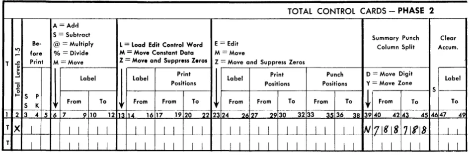
Phase 2 (Form No. X24-6558)
Total Control Cards
These cards, always punched T in column' 1, specify the various operations to be performed for each class
of total or each total within the same class. Operations
include:
1. Skip to a carriage tape channel, space before and/or after total printing, or eject from form to form.
2. Add one total-level accumulator to a higher-level accumulator. Subtract one total-level accumulator from a higher-level accumulator. Multiply or di-vide one total by another on the same level. 3. Crossfoot totals on any total level desired.
4. Load or move constant data to the printer output area.
5. Move, move and suppress zeros, or edit accumu-lated totals to the print or punch areas.
6. Move digits or zones from a single storage position. For example, remove or add a sign to the units position of a total.
7. Clear accumulators.
8. Print constants on totailleveis to identify totals. 9. Print totals on total lines.
10. Print multiple lines of information read from a single card in Phase 3.
11. Punch summary cards.
Several totals within the same class, designated by Held headings, may be printed horizontally on the same line, each under its appropriate column of the report. Or, they may be identified by constants and printed vertically on separate lines in the same col-umn of the report. Examples:
Gross Earnings
150.00
Horizontal Method
Withholding Tax 27.00 F.I.C.A. 5.44 Other Deductions 10.00
Vertical Method
Gross Earnings 150.00 Less WHTax 27.00 F.I.C.A. 5.44 Other 10.00 Net Pay 107.56*
Net Pay 107.56
Similarly, different classes of totals may be printed horizontally under designated report columns or ver-tically in the same report column.
Total-control-card specifications are recorded in columns 1 to 56 as follows.
Card Columns 1 2 3-4 5 6
7-9 (from) 10-12 (to) 13
14-16
17-19 (from) 20-22 (to) 23
Control Data
T - Total control card. 1 - Minor-totallevel. 2 - IntermedIate-total level. 3 - Major-total level. 4 - Fourth-total level.
5 - Fifth- (final) total level. (Occurs on last card ronout with Sense Switch A turned ON.)
SP - Space before total printing. SK - Skip before total printing.
Enter 1-3 to space number of times desig-nated.
Enter 4-9 to skip to corresponding carriage tape channels.
NOTE: Because normal single spacing is automatic, leave columns 3-5 blank
if normal spacing is desired. A - Add.
S - Subtract.
@ - Multiply (4-8 punch).
% - Divide (0-4-8 punch). M - Move.
Label of accumulator read out of. Label of accumulator read into. L - Load edit control word. M - Move constant data. Z - Move and suppress zeros.
Label assigned to constant being moved or loaded.
Print positions selected to print constant data.
E - Edit total or constant data. M - Move total or constant data.
Card Columns
24-26
27 -29 (from) 30-32 (to)
33-35 (from) 36-38 (to)
Control Data
Label assigned to accumulator or constant.
Print positions selected to print total or con-stant data addressed by the label coded in columns 24-26 of the same control card.
Summary-card columns selected to punch total or constant data addressed by the label coded in columns 24-26 of the same control card.
RULE: For printing and punching from the same accumulator, two separate control cards are required. One moves data to print positions, and the other moves data to punch positions.
39
40-42
4.3-4.5
46
47-49
D - Move digit (only) portion of a charac-ter from one card column to another in punch area.
Y - Move zone (only).
Summary-card column from which digit or zone is to be moved.
Summary-card column to which digit or zone is to be moved.
S - Clear accumulator by subtracting it from itself.
Label assigned to accumulator to be cleared.
NOTE: When both printing and punching from the same ac-cumulator, clear accumulator on the second control card, after information has becn transferred to the print and punch areas.
50
51
52-53
P - Print total line. All totals within the same level may be printed on one line or on separate lines.
P - Punch total summary card. All totals within the same level may be punched ill one card or in separate summary cards.
SP - Space after total printing. SK - Skip after total printing.
Card
Columns Control Data
54 Enter S to single space.
Enter 1-3 to obtain additional spaces beyond the normal &ingle space (1 for double space, 2 for triple space, 3 for quad-mple space).
Enter 1-9 to skip to corresponding carriage tape channels.
NOTE: When skipping to carriage-tape channel-1 after total printing, report and field headings do not print.
RULE: When several totals within the same level are printed on separate lines, the last T (Total) control card for each
total level must contain a Skip, Space, or Eject instmc-tion. If normal single spacing is desired, the last control card must be coded SPS in columns 52-54.
55
56
E - Eject form to carriage-tape channel-1 after total printing. Report and field headings will print on the next page following the eject.
(J The last T control card specified in
Phase 2 (Form No. X24-6558) must
contain an asterisk (<:I) punch in
col-umn56.
RULE: \Vhen four control levels are specified in the problem, final-total operations are specified on level 5. When less than four control levels are specified, final-total operations are specified on the next higher level. Examples:
No controls, final-total operations are specified on level 1.
Minor control only (level 1), final-total operations are specificd on level 2.
Minor and intermediate controls (levels 1 and 2, re-spectively), final-total operations are specified on level 3.
Minor, intermediate and major controls (levels 1, 2 and 3, respectively), final-total operations are speci-fied on level 4.
For all the conditions mentioned in these examples, the last final-total control card must contain an asterisk
(<:I) punch in column 56.
If Final Totals are not required, a last-card-runout
total-card for levell, 2, 3, 4 or 5 must contain an
asterisk in column 56.
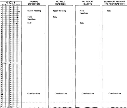
Automatic-Carriage-Control Operation Page overflow is controlled by the letter 0 in column 3 of the master-report control card - Phase l. Ejecting from form to form (carriage-tape channels 12 to 1), and skipping to carriage-tape channels 2 and 3, occur auto-matically as shown in Figure 3, depending on the presence or absence of report- and field-headings
COIl-trol cards - Phase 4.
G L:U E
C~~~~~N
~=. ··ir:r"'r",;:,;w:":;"':":;:--+--Re=-po-rt-frl~~ea-d-ing---'
... +.
'"
-+.
=
~
.
:=I:S:: • • • , ... .,UI .... W N _
I!!I
...
...
t:;
it
Field Headings
Body
Overflow line
...+~
I:: I-H--I-II+ .. .-+-, H, '+1++1
-...
·-hit
g -.~
NO FIELD HEADINGS
Report Heading
Body
Overflow line
Figure 3. Automatic-Carriage-Control Operation
-NO REPORT HEADING
Field Headings
Body
Overflow line
NO REPORT HEADING NO FIELD HEAD INGS
Body
[image:15.615.85.523.332.704.2]Operating Instructions
To prepare reports with FARGO, proceed as follows:
l. Ready the IBM 1403 Printer.
a. Insert into the carriage the paper or form on which the report is to be printed. Make the neces-sary vertical and horizontal adjustments to properly position the form.
b. Insert the carriage tape punched as follows.
Normal Condition
Channell- Report-heading line. Channel 2 - First field-heading line. Channel 3 - First body line.
Channels 4-9, if required. Skip-stops for pre-determined line printing.
Channel 12 - Overflow line.
NOTE: For conditions other than normal, channels
2 and/or 3 may not be required. (See Figure 3.) c. Set feed-clutch knob to neutral position.
d. Press carriage-restore key.
e. Turn feed-clutch knob back to drive position. f. Press check-reset key on the 1403 printer. 2. Ready the 1401 Console.
a. Set mode switch to run position.
b. Set I/O check-stop switch to the ON (up)
posi-tion.
c. Set sense switch A to the ON (up) position.
d. Press check-reset key on the 1401 console. e. Press the start-reset key on the 1401 console. 3. Ready the 1402 read-punch unit.
a. Set reader switch to ON.
b. Press the non-process runout read key to clear the read feed.
c. Place FARGO program and detail cards in the 1402 read unit in the sequence illustrated in Fig-ures lor 6.
d. If summary punching, set punch switch to the
ON position.
1. Press the non-process runout punch key to clear the punch feed.
2. Place cards to be summary punched in the punch hopper.
e. Press check-reset key on the 1402 read-punch unit.
f. Press load key on the 1402 read-punch unit.
If the control cards punched from the FARGO
cod-ing sheets contain no errors, the program is loaded in approximately 20 seconds. Processing of detail data cards is started immediately thereafter. When the last card has left the hopper and the machine stops, press the start key on the 1402. If specified in the program, final totals print automatically on the runout.
Program Halts
Program halts may occur not only during the loading of the FARGO program deck (Phases 1 to 4) but also during processing of the detail cards. Halts occurring during Phases 1 to 4 indicate that the control cards punched from the coding sheets are not in the proper sequence as shown in Figure l. Or, if they are in the proper sequence, invalid codes are punched in column 1 of the control cards. Valid codes are M, B, C, S, T,
D, H, F, or
#.
Codes other than these are invalid. Following is a list of program halts, reason for halt, and procedure for restarting. When the halt occurs, the last card in the read stacker (NR) has an invalid code in column 1.Storage Address
Displayed Phase Reason for Halt
2639 1 Card has other than M.
2947 1 Card has other than B, C, or S. 2363 2 Card has other than T.
2379 3 Card has other than D.
3090 4 Card has other than H, F, or #. To restart from any of these halts, proceed as follows. 1. Remove cards from read hopper.
2. Press non-process runout read key.
3. Remove the last three cards from the read stacker (NR). The first of these three cards is the control card in error.
4. Correct the error.
5. Replace the three cards in front of the cards taken from the read hopper.
6. Place the card file in the read hopper. 7. Press check reset key on the 1402.
CAUTION: Do not press the start reset key on the 1401
console.
8. Press start key on the 1402 read unit.
During processing of detail cards, if the machine stops with the red Stop Light ON (1401 Console) and
storage address 0157 displayed, a constants label has been referred to in one of the T or D control cards for which there is no corresponding constants control card. This may be due to misspelling the 3-character label abbreviation on the T or D control card. Or, it may be that constants control card was inadvertently omit-ted in the constants coding sheet. To restart, proceed as follows.
l. Remove all cards from read hopper and file feed. 2. Press non-process run out read key on the 1402. 3. Locate erroneous control card, make corrections,
and restart from the beginning.
If the machine stops with the red Stop Light ON and
During processing of detaH cards, the program may hang up at an unknown address with the following lights ON:
PROCESS
CHECK RESET
A- DEl I-ADDRESS REGISTER.
The A·Address Register Light means that an edit control word entered in the constants coding sheet is too small for the data being edited. The I-Address Register Light means that a 1401 operation code rep-resented by an invalid character is detected in storage.
To locate the edit control word that is too small for the data being edited, execute a STORAGE PRINT-OUT as
follows.
1. Set mode switch to STORAGE PRINT-OUT.
2. Press I-address register key and note address loca-tion displayed.
3. Turn hundreds and thousands manual-address switches to digits corresponding to the hundreds and thousands positions displayed.
4. Press start key on the 1401 console.
5. Examine the storage print-out and find the I-address displayed in Step 2.
6. Go back from there to the first load (L) instruction. The A·operand of this instruction contains the stor-age address of the edit control word that is too small.
7. Locate constants control card, make corrections, and restart from the beginning.
To locate and correct an invalid character used as an operation code execute a STORAGE SCAN as follows.
1. Set mode switch to STORAGE SCAN.
2. Set manual-address switches to 0000. 3. Hold down the start key.
4. Machine stops when an invalid character is detected in storage. The storage position in error is shown in the storage-address display unit. The B-register dis-plays the contents of the storage position in which the error is detected.
E - Edit
5. Locate the control card in which the invalid charac-ter is punched and remove it from the program deck.
6. Correct the error by punching a new control card and inserting it in the program deck.
7. To restart, a complete card run out and start reset is necessary.
Patching
The term patching as used in connection with FARGO, means linking a special subroutine or library program
to the main FARGO program. The linkage is accom-plished by branching from' a specific patch point in Phase 3 (detail control cards) or Phase 2 (total control cards) to the patch subroutine, then branching back to the main FARGO program, after the subroutine is executed.
With a 4k machine, at least 956 storage positions are available for storing patch subroutines. In some cases, depending upon the complexity of the report involved, more storage positions may be available. These subroutines must be entered into the machine in actual 1401 machine language. Therefore, a knowl-edge of 1401 programming or symbolic programming (SPS) is a prerequisite.
The specific patch pOint(s) for linking subroutines is determined by the programmer as he normally writes the FARGO instructions. These patch points are first recorded on Phase 3 and Phase 2 coding sheets as 4- or 7 -position no-op instructions. They are changed later to unconditional branch instructions after the· exact locations of the patch subroutines are deter-mined.
Phase
3 -
Detail No-Op ControlCards
At each point in Phase 3 where branching to sub-routines is required, make an entry on the coding sheet in columns 1, 2-6, and 7-10 as shown in Figure 4.
Del AIL CONTROL CARDS - PHASE 3
E = Edit
l = load Edit Control Word DETAil CARD DATA M = Mov.
M = Moye Constant Data Typ. of
Z = Moye and Suppress Z.ros Z = May. and Suppr ... Zeros D.tail Special" or o
=
Mov. Digit D = Mov. DigitCard 7 position Column Split Y
=
Moye Zone Y = Mov. Zan. 01-'01 Instruction
C
=
Chal'. o =: Moye Digit Print Punch Data Card Print Punch Z=
ZonE+- (adual) Y :: Moye Zone label Positions Positions Columns Positions Positions .,
C 0
11
...
"0
Card
a
U Cois. Z P A B From To From From To From To From To From To From To 1 2 3 5 6 7 8 10 1 13 1" 15 1718 202 122 2" 25 27128. 3~ 31 3 34 36 3738 40141 43 ... .u. '7 4950 §2 53 55
OX
XtXlx Ix N 01010 I I I I I I I I I I I I I I I I I I I I I I I I I I i I0 I I I i I I I I I I I I I I I I I I I I I I I I I I I I I I
Figure 4
[image:17.612.65.567.560.709.2]The D in column 1 is preprinted on the form. This indicates that branching to the patch subroutine is to occur during the detail portion of the program. The codes entered in columns 2-6 specify the type of detail card for which the patch subroutine is to be executed. The entry, NOOO in columns 7-10, is the no-op instruc-tion. This is changed later to an unconditional branch instruction (~xxx), with xxx indicating the actual ma-chine address of the patch subroutine.
Phase
2 -Total
No-OpControl
CardsAt each point in Phase 2 where branching to sub-routines is required, make an entry on the coding sheet in columns 1, 2, and 39-45 as shown in Figure 5.
The T in column 1 is preprinted on the form and indicates that branching to the patch subroutine is to occur during the total portion of the program. Any digit from 1 to 5 entered in column 2 specifies the program level during which the patch subroutine is to be executed. The entry N788788 in columns 39-45 is the no-op instruction. This must be changed later by an instruction in the patch subroutine to an uncon-ditional branch instruction (~xxxbbb), with xxx indicat-ing the actual machine address of the patch subroutine and bbb indicating blanks.
The FARGO program, including the no-op control cards that cause no machine operation, is completely tested with a representative deck of detail data cards and approved before the subroutines are inserted in-to the program deck. This is necessary because any change in the FARGO control cards after the sub-routines are inserted affects the storage locations of the
A =Adr.l S = Subtract
Be- @ = Multiply L = Load Edit Control Word E = Edit
'? fore % = Divide M = Move Constant Data M = Move
gencrated report program, requiring changes in the subroutine instructions.
After the FARGO-generated portion of the report is satisfactorily tested, execute a STORAGE PRINT-OUT
and examine it to determine:
1. the end of the FARGO-generated program.
2. storage location of patch points (no-op detail and total control cards).
The end of the generated program is determined by locating the report-heading information that is loaded into storage immediately after the last instruction from the detail control cards. If report-heading information is not specified in Phase 4, the end of the generated program is the last ~E66 instruction. This instruction appears follOWing the last generated instruction for each type of detail card specified in Phase 3. There-fore, the end of the generated program is either the last position of the report-heading information (includ-ing blanks), or the last BE66 instruction. The area available for storing the-patch subroutines extends from this point (storage location 2358 or lower, depend-ing upon the complexity of the report involved) to 3313. Thus, with a 4k machine, 956 storage positions or more are available for patch subroutines. Obviously, with machines of greater capacity, an additional amount of storage is available, starting with location 4000.
The storage location of each patch point is deter-mined by visually scanning the storage print-out and finding the no-op instructions. Detail no-op instructions are identified by NOOO. Total no-op instructions are identified by N888888. ~888888 was recorded on the coding sheet as N788788 but changed by the FARGO program to ~888888.
TOT AL CONTROL CARDS - PHASE 2
Summary Punch Clear Column Split Accum.
T "i Print M = Move Z
=
Move and Suppress Z.ros Z = Move and Suppress Zeros->
1
1
1
.! Label Label Print
Label Print Punch D = Move Digit Label
'] Positions Positions Positions Y = Move Zone
0
~
S-... S P
S K From To From From To From From To From To From To To
~ 6 7 9 10 113 114 22 23124 26 f---- 33 35 38 139 - -4l 45 49
1 2 3 4 5 12 16 17 1920 127 _29 30 32 36 40 42 4647
T X I I I I I I I I I I I I I I I I I I I I~ N
~lli~
Zlilt
J __ L
-T I I I I I I I I I
II I I I I I I I I I I I I I I I I
[image:18.613.46.519.549.705.2]Converting No-Op Instructions
The control card containing the detail no-op
instruc-tion (~OOO) may be removed from the FARGO deck
and replaced with a control card containing an un-conditional branch instruction ]xxx. Or, it may remain in the deck in which case the no-op instruction must be converted to an unconditional branch instruction
~xxx by an instruction in the patch subroutine. The control card containing the total no-op instruc-tion a~:7BB7BB) always remains in the FARGO deck. The nOl-op instruction, therefore, must be converted to an unconditional branch instruction Bxxxbbb by an instruction in the patch subroutine.
Codin!1 the Patch Subroutines
As previously stated, a patch subroutine must be en-tered in storage in actual 1401 machine language. It may be written in symbolic language and assembled with an assembly processor as described in IBM 1401 Symoblic Programming Systems, Form C24-1480.
To branch back to the main FARGO routine after the subroutine is executed, the last instruction in each patch subroutine must be an unconditional branch in-struction. For example, if a detail (Phase 3) no-op instruction (~OOO converted to ~xxx) is in locations
1445-144B as noted in the storage print-out, the last instruction in the subroutine used at this point must branch back to 1449. If a total (Phase 2) no-op instruc-tion (N~BBBBB converted to ~xxxbbb) is in locations 1201-1207 as noted in the storage print-out, the last instruction in the subroutine used at this point must branch back to location 120B.
If coded in SPS, the program is assembled after testing the FARGO portion of the job so that the origin address of the subroutine can be determined from the storage print-out. When the object program deck is created by the SPS assembly processor, the first two cards contain instructions to clear storage. These two cards must be removed from the deck. The rest of the
object program deck (one instruction per card) can then be loaded directly behind Phase-4 control cards. Or it can first be condensed into multiple instructions per card with a condensing program as described in
IBM 1401 Symbolic Programming Systems, Form C24-1480.
An example of a patch subroutine coded in actual machine language is shown in Figure 23-G. Another example of FARGO patching and linkage using SPS is shown in Figure 24.
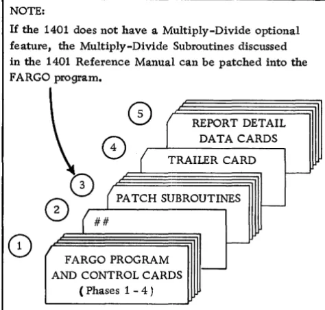
NOTE:
If the 1401 does not have a Multiply-Divide optional feature, the Multiply-Divide Subroutines discussed in the 1401 Reference Manual can be patched into the FARGO program.
1
fs\(
\V REPORT DETAIL
o
DATA CARDS4 ( TRAILER CARD
o
CD
(PATCH SUBROUTINES c-{ ##
0/~~~~~
FARGO PROGRAM AND CONTROL CARDS
(Phases 1 - 4 )
-1. Combined FARGO Program and FARGO Control Cards
2. Last card in Phase 4 punched # in columns 1 and 2
3. Patch subroutine(s)
4. Trailer card containing instructions to clear the read-in area, and branch to 3314(C14).
s.
Report Detail Data CardsFigure 6. FARGO with Patch Subroutine
Loading the Patch Subroutines
All patch subroutines are loaded immediately after the Phase-4 control cards. Normally, the last Phase-4 control card is punched
#
in column 1 of a blank card. To signal the FARGO program that patch-subroutine instruction cards are to be read into the system after Phase 4 is completed, this same card must also have a#
punched in column 2. This causes the program to clear the read-in area (locations I-BO), set a wordmark in location 001, read the next card, and then branch to location 001.
After the last patch subroutine is loaded, a clear-and-branch trailer card must follow to clear the read-in area, and branch to location C14 (3314), this beread-ing the starting location of the permanent FARGO pro-gram. The report detail cards immediately follow the trailer card.
The cards are run through the machine in the se-quence illustrated in Figure 6.
[image:19.615.339.576.67.293.2]Multiply-Divide Optional Feature
If the multiply-divide optional feature is installed in the 1401, direct multiplication and division can be specified with FARGO detail and/or total (Phases 3 and 2) control cards. Before the proper entries can be made in these coding sheets, however, several factors must be considered.
Multiplication
Whenever FARGO report specifications involve a mul-tiplying operation, the first thing that must be decided is the size of the product to be developed. As explained in the IBM 1401 Data Processing System Reference Manual, A24-1403, this is done by adding 1 to the
sum of the number of digits in the multiplier and the multiplicand. Assuming a 3-digit multiplier and a 4-digit multiplicand, the size of the product can then be readily determined by the following formula:
3 (multiplier) plus 4 (multiplicand) plus 1 = 8 (size of product). The multiplier may be fixed; that is, not punched in the detail cards but set up as a constant with an identifying label in Phase 1 for later reference in
Phases 3 or 2. Or, it may be variable; that is, punched in each detail card or some specific type of card within a control group.
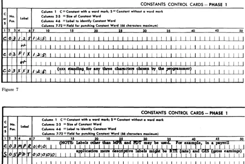
A fixed multiplier (example: 125) may be set up as a constant in one of several ways as shown in Figure 7. A variable multiplier may be punched in known columns of all or specific types of detail cards.
Multiplicands are always variable and may be punched in known columns of all or specific types of detail cards. Or, they may be developed as a total in an accumulator and identified with an appropriate label. Although any 1-, 2-, or 3-character label may be used to identify an accumulator, many users of F ARGO prefer to use labels corresponding to 407 counters; for example, 2A, 2B, etc., 4A, 4B, etc.
Experience has shown that this method of labeling accumulators often simplifies the conversion of report specifications from the 407 to the 1401.
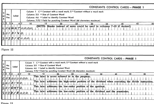
Having determined the size of the product, set up a work area in storage for developing and retrieving the product. This is done by making two successive entries on the constants control cards coding-sheet (Phase 1) as shown in Figure 8.
CONSTANTS CONTROL CARDS - PHASE
C No.
~ Pos. Label
Column 1 C = Conltant with a word mark; 5 = Constant without a word mark
Columnl 2·3
=
Size of Conltant WordColumnl 4-6
=
Label to identify Conltant WordColumnl 7·72
=
Field for punchinG Conltant Word (66 characters maximum)1 2 10 15 40 45 50
co
I I I I I I [image:20.617.39.531.376.705.2]co
Figure 7
CONSTANTS CONTROL CARDS - PHASE
Label
Column 1 C
=
Conltant with a word mark; 5=
Conltant without a word mark C No.or
S Pos.
The first entry, C (constant with a word mark), sets up the three high-order (left-hand) positions of the product work area into which the 3-digit fixed or variable multiplier will be moved later with a T or D control card.
The second entry, S (constant without a word mark), sets up the five low-order (right-hand) positions of the product work area, thus establishing an 8-position product work area somewhere in storage.
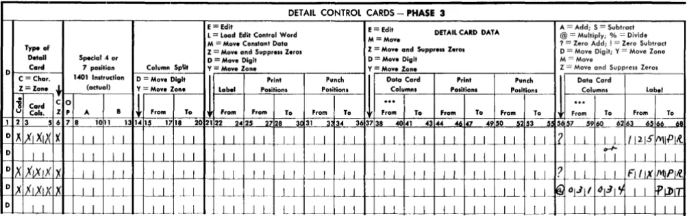
Multiplying in Phase 3 with a Fixed Multiplier Multiplying with a fixed multiplier (125) can be spe·· cified flOr all or any specific type of detail card by making the entries in columns 56-68 as shown in Figure 9.
The first or second entry? (whichever one is used) zeros (resets) and adds the constant 125 in the three high-order (left-hand) positions of the product area.
Entry @ multiplies the 4-digit multiplicand punched in columns 31-34 of the detail card by the fixed multi·· plier (125). When the multiplying operation is com-pleted, the product is in the seven low-order positions of the product area, thus destroying the multiplier. The
fixed multiplier, however, is still available for subse-quent operations from the area labeled 125 or FIX.
Following the multiply operation @, another entry moves the product either to print positions and/or to an accumulator identified by a constant label. If the product is to be punctuated, an edit control word is first loaded into the desired print positions. The prod-duct is then moved to the same print positions with an E (edit) instruction.
Multiplying in Phase 3 with a Variable Multiplier Multiplying with a variable multiplier can be specified for all or any specific type of detail card by making the entries in columns 56-68 as shown in Figure 10.
Entry? zeros (resets) and adds the variable 3-digit multiplier punched in columns 21-23 of the detail card into the three high-order (MPR) positions of the product area.
Entry @ multiplies the 4-digit multiplicand punched in columns 31-34 of the detail card by the variable 3-digit multiplier punched in columns 21-23 of the same card. The product is developed in the same manner as previously described.
DETAil CONTROL CARDS - PHASE 3
E= Edit E = Edit A = Add; S = Subtract
L = Load Edit Control Word DETAIL CARD DATA @ = Multiply; % = Divide M = Move Constant Data M = Move ? = Zero Add; ! = Zero Subtract Type al' Z = Move and Suppress Z.ros Z = Move and Suppr ... Zerol D = Move Digit; Y = Move Zone
Detail Special.' or o = Move Digit D = Mov. Digit M = Move
0 Card 7 pOlition Column Split Y=Move Zone Y = Move Zone Z = Move and Suppress Zeros
C = Char. 1401 Inltruclion o = Move Digit Print
''"~
1
Data Card Print Punch Data CardZ = Zane ~ (actual) Y = Mov. Zone
I
~~I
POlitionl Po"itl~~ Calumnl POlltionl Posltio~~ Columns Lobeli Card C 0
!
...
.
..
u Call. I P A B From To From From To From To From To From To From To From To From To 1 2 3 5 6 7 8 1011 131415 1718 202122 3~ 31 363738 46 47 5253 ~.~
-_.---c
63-65 iM~ 2425 2728 ~ 34 4041 4344 4950 5 57 59 60 62
o " XI XIX X I I I I I-.L I I LL -LL .~Ll ~ _LL _LI I I I I I.L __ Ll ~.LL LL
2
LLf-!;)-
l~lS 1\'Ul'l~0
I I I I I I I I I I I I I I 1 1 1 1 LI L J 1 1 l..l 1 1 1 I LL t--_LJ~_ r-L1 1 1 L_L
OX
,xIXIXIX I I I I I 1 I I U I I I I I I I I I I I I I I I L __ l-.-l_ ~LL2-
LL r---ll FI/IX IMjPI!i~X flXlxlX I I I I I I l L r~~ LL __ LL _LL -.l.L_ _L I I J I I I I I I J_L LJ_ ~Ol~( _~~I't I I fjl)IT 0 I I
I I ---LL '--_LL ~LL LL ~JL LL I I 11 I I LL LLLLLL ~LL __ LJ _ ~ I I I I I I I I
Figure 9
DETAil CONTROL CARDS - PHASE 3
E = Edil E = Edit A = Add; S = Subtract L = load Edit Control Word DETAIL CARD DATA @ = Multiply; % = Divide M = Move Constant Data M = Move ? = Zero Add; ! = Zero Subtract Type of
Z = Move and Suppress Zeros Z = Move and Suppress Zerol o = Move Digit; Y = Move Zone Detail Special 4 or o = Move Digit o = Move Digit M = Move
0 Card 7 pOliti on Column Spilt Y = Move Zone Y = Move Zone Z = Move and Suppress Zeros 1401 Instruction
1
-C - -Chaw. o = Move Digit Prinl Punch Data Card Print Punch Data Card
Z = Zon .. ~ (actuol) Y = Move Zone
I
~~I
Position. Position I Columnl Posi.tions Positi"_1!!- Columns labeli Card C 0
!
...
. ..
U Call. Z p A B From To From From To From To From To From To From To From To From To 1 2 3 5 6 7 8 1011 131415 1718 20 2122 2425 2728 30~3--: 34~ 363738 _4041 4344 4647 4950--s253 55 5 57 5960 6263 6566 611
OX
XIXU(lX.W-l--
_LL I~_ .~ .. l~--.l ~LL JJ_ --.ll ~Ll LJ~ _ I L_ .J._J I I I I Ll .Ll _ _LL L~8J! ~L2JJ I I '1IPl~ o .,x XIXlxlx I I I I I I I I I I ~L I I I I _J_L I I I I I I I I U ~ I I ~Oj.J11 1.>1) 11 I I ~~JI0
I I I I I I I I I I I I I I I I I I -11 I I I J 11
LLl-
~LL.LL _-LL I I I I JlFigure 10
[image:21.615.78.580.382.540.2] [image:21.615.82.576.575.715.2]Multiplying in Phase 2
Multiplying in Phase 2 (total control cards) always involves three labels. One label identifies a fixed- or group-multiplier. A second label identifies an accumu-lated multiplicand, while a third label identifies the product.
In establishing the size of the product, the same rule applies. However, because the multiplicand factor is an accumulated total, the maximum number of digits expected in the multiplicand must be
predeter-mined before setting up a product work area.
Having determined the size of the product, make the appropriate C and S entries on the constants con-trol cards coding-sheet (Phase 1) to set up the product work area.
During the Phase-3 (detail) portion of the program, a fixed multiplier set up with a constant control card, or a group multiplier punched in a specific detail card within the control group, is moved to the MPR portion of the product work area. The detail multiplicands are accumulated in a storage area labeled, for example, M CD. On any given total level in Phase 2,
multipli-cation is specified by making the entry in columns 6-12 as shown in Figure 11.
Entry @ multiplies the accumulated multiplicand
labeled MCD (or any other label chosen by the pro-grammer) by the fixed- or group-multiplier moved to the MPR portion of the product work area during Phase 3. The product is developed in the product work
A = Add S = Subtract
Be- @ = Multiply L
=
Load Edit Control Word E = Edit~ fore % = Divide M
=
Move Constant Data M = Movearea labeled PDT (or any other label chosen by the programmer). For example, in a payroll application, the multiplier might be labeled RTE (rate), the mul-tiplicand HRS (hours), and the product GES (gross earnings). In another application, the multiplier might be labeled UNP (unit price), the multiplicand QTY (quantity), and the product AMT (amount).
Division
Whenever FARGO report specifications involve a di-viding operation, a work area for accommodating the dividend and developing the quotient and dividendi remainder must be set up in storage with constants control cards in Phase 1. The size of this work area must be equal to the sum of the number of digits in the divisor and dividend, plus 1. Assuming a 3-digit di-visor and a 4-digit dividend, the size of the work area can be readily determined by the following formula:
3 (divisor) plus 4 (dividend) plus 1 = B-position work area. Having determi