2016 3rd International Conference on Information and Communication Technology for Education (ICTE 2016) ISBN: 978-1-60595-372-4
1. INTRODUCTION
In recent years, as the rapid development of the high-speed rail technology, this also effectively improved the shortage on the transport capacity of railway passenger. One of the main characteristics of high-speed trains has complex pantograph-catenary relation, therefore, higher requests about pantograph-catenary system vibration, noise, and current-collection quality have been made [1]. With the further increase of the train speed, the coupled vibration of pantograph-catenary system will be more intense, causing off-line, arcing and pantograph strip wear seriously affected by flow quality, which caused the potential safety troubles during the high-speed operation[2]. As a result, it is of great significance to study the dynamic characteristics of the contact pressure between the high-speed pantograph-catenary system and its suppression measures.
In order to overcome the volatility of catenary-pantograph contact pressure, domestic and foreign scholars put forward the idea of pantograph active control. The original idea is based on the current states of a pantograph-catenary system, pantograph applied external controllable, the flexible adjustment of the pantograph uplift, which can significantly reduce the pantograph-catenary contact pressure fluctuation [3].According to the above ideas, a variety
of pantograph active control strategies have been proposed, including the LQR optimal control [1-4], synovial variable structure control [2,5-8], and fuzzy control[2,9,10], etc. The LQR optimal control is using the minimum of the system performance index as the evaluation function to determine the pantograph optimal active control force, the synovial variable structure control through the rational design of switching function can achieve the optimal active control force of robust control, and fuzzy control is based on the nonlinear variation and time varying characteristics of the pantograph-catenary contact pressure, to establish a suitable fuzzy reasoning machine, achieving effective fuzzy control rule.
However, all realization procedure of the control strategy above require the experience design of the key parameters inevitably. For LQR optimal control, the state weight matrix and weight coefficients of the control force need experience selection; for synovial variable structure control, the prediction factor and target feature values of the key parameters need empirical calculation. Also, for the fuzzy control, the establishment of the fuzzy control rule and the reasonable choice of the input value are all required the accumulations of prior knowledge.
To sum up, the existing literature and documents about the control strategy design are not only need the experience design of key parameters, but also are unable to realize the accurate model control though
Globally Active Feedback-Linearization Control Strategy for
Pantograph-Catenary System
Zhe Zhuang, Ying Shi, Xieqi Chen
State key laboratory of Traction Power, Southwest Jiaotong University, Chengdu, China
ABSTRACT: The research of the dynamic characteristics of the contact force in high speed pantograph-catenary system and its restraint is essential for the reliable operation of the high-speed train. In order to overcome the shortcoming of the existing active control strategies, this article introduces a globally linear active control strategy for the pantograph-catenary system of feedback-linearization, basing on the ternary pantograph-catenary dynamic modeling. The parameter cluster could be optimized through the zero-poles configuration in classic control theory, also, its effectiveness was validated compared with the LQR optimum control. The simulation result shows, during widely operation speed range, there exists more than 30% derating on the standard deviation under the contact force of pantograph-catenary system compared with that in present global linear active control strategy. Meanwhile, a better tracking result for expectation mean value of the contact force can be realized, therefore, the advantage of this strategy is verified.
the strict theoretical analysis, and thereby also inevitably weakens the target contact pressure. For example, as the LQR optimal design, the optimal dynamic contact pressure is regulated by the state weighting matrix and control weight coefficient dynamically. Therefore, based on the pantograph-catenary coupling model, the design method of the control strategy is constructed through the model analysis, which can restrain the contact pressure of pantograph-catenary under the fixed target control force.
1.1 Pantograph-catenary system vibration coupling model
Vibration of the pantograph-catenary system is a complex dynamic system, for the convenience of study. Usually, a common way in the dynamic behavior is simplifying the pantograph and contact line network, and obtained the mathematical model, then through the coupling conditions establish the dynamics model of the pantograph-catenary system. During the simplified analysis, the contact network and pantograph are usually simplified as follows.
Due to the periodical variation of the stiffness of the contact net in the span and inter - span, the contact network is equivalent to the variable stiffness spring system in the course of the high-speed train operation;
For pantograph. In the research of the pantograph and catenary system, mainly have imputation quality block model, multi rigid body model, the rigid flexible hybrid model and fully compliant model form, this paper chooses much higher dynamic characteristics under the three degree of freedom imputation quality pantograph model.
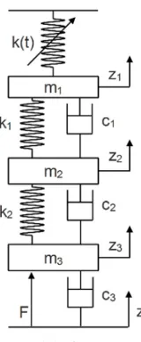
To sum up, the pantograph-catenary coupling vibration system is established as shown in Figure 1. The k (t) simplified equivalent of the catenary of the variable stiffness spring system; zi,mi,ci and ki respectively by the pantograph head, frame, a lower frame displacement, equivalent mass, equivalent damping coefficient and equivalent stiffness; F integrated static lift force for active control of force, considering from the practical part[11],it is necessary to set the imposed active control force and static lift force in the same position under the framework of the application.
(a)Overall system structure
(b) Vibration coupling model of pantograph catenary system Figure 1 Pantograph-catenary system of high-speed railway with schematic of the equivalent model.
For the catenary equivalent variable stiffness spring system k (t), the usual modeling method [12] is to obtain the contact finite element model of network, and take the generalized least squares corresponding to the stiffness curve. The results such as formula (1) shown:
( )
(
2 2 2)
0 1 1 1 2 2 3 1 4 3 5 4
k t =k +α f +α f +α f +α f +α f
(1) Among,
(
)
(
)
(
)
(
)
1 2 1
3 4 1
cos 2 , cos 2
cos , cos
f vt L f vt L
f vt L f vt L
π π
π π
= =
= =
(2)
Where, k0 is the average stiffness coefficient, N/m;αi is stiffness coefficient of variation; and v
represents the speed of the train, m/s; L is the span of the catenary, m;L1is the length between catenary adjacent hanger, M.
[image:2.612.393.473.27.220.2]In this paper, we use the typical simple chain suspension catenary parameters [1] for simulation, and the simulation parameters are shown in table 1.
Table 1. Typical parameters for overhead contact system in single catenary system.
k0 α1 α2 α3 α4 α5
3684.5 0.4665 0.0832 0.2603 -0.2801 -0.3364 According to the formula (1) ~ (2) contact net equivalent variable stiffness spring system k(t), the pantograph-catenary system in Figure 1 is analyzed, and the pantograph-catenary coupling dynamic equation can work out as below:
(
)
(
)
( )
(
)
(
)
(
)
(
)
(
)
(
)
(
)
1 1 1 1 2 1 1 2 1
2 2 1 2 1 2 2 3
1 2 1 2 2 3
3 3 2 3 2 2 3 2 3 3 r
m z k z z c z z k t z
m z k z z k z z
c z z c z z
m z F k z z c z z c z z
= − − − − −
= − − − −
− − − −
= − − − − − −
(3)
[image:2.612.63.283.611.702.2][
]
[
]
1 2 3 4 5 6
1 1 2 2 3 3
, , , , ,
, , , , ,
T
T x x x x x x
z z z z z z = = X (4) Input vector:
( )
u t =F
(5) The state equation of the pantograph-catenary coupled nonlinear control system is followed as below:
X AX Bu Dw Y CX = + + = (6)
Among them, the origin of the simulation for the vehicle on the pantograph excitation which used for the white noise is shown below:
[
]
( )
1 2 3 4 5 6
3
3
3
1
0 0 0 0 0
0 0 0 0 0
0 0 0 0 0
T
T
T
A A A A A A A
B
m
C k t
c D m = = = = (7)
In formula (7), the matrix elements of the state space equation in the coefficient matrix A of the pantograph-catenary system are expressed as,
[
]
( )
[
]
[
]
1
1 1 1 1
2
1 1 1 1
3
1 1 1 2 1 2 2 2
4
2 2 2 2 2 2
5
2 3
2 2 2
6
3 3 3 3
0 1 0 0 0 0
0 0
0 0 0 1 0 0
0 0 0 0 0 1
0 0
A
k k t c k c
A
m m m m
A
k c k k c c k c
A
m m m m m m
A
c c
k c k
A
m m m m
= + = − − = + + = − − = + = − − (8)
2. STATE FEEDBACK LINEARIZATION OF PANTOGRAPH-CATENARY VIBRATION COUPLED SYSTEM
For the type (6) of the pantograph-catenary coupling nonlinear control system, whose output variable is:
( )
( )
1y=h x =k t x
(9) After deformation which can be applied to the differential geometric method of single input, single output of pantograph-catenary contact force have affinity with the nonlinear control system state equation as shown in the formula (10).
( )
( )
( )
( )
( )
11
w
f g u g w
y h k t x
= + + = =
x x x x
x
(10)
Among them, the vector function f(x), g(x) and
gw(x) is expressed as,
[
]
( )
( )
1 2 3 4 5 6
1
3
3 3
1
0 0 0 0 0
0 0 0 0 0
T
T
T
w
f f f f f f f
g x m c g x m = = = (11)
( )
1 21 1 1 1
2 1 2 3 4
1 1 1 1
3 4
1 1 1 2
4 1 2 3
2 2 2
1 2 2 2
4 5 6
2 2 2
5 6
2 3
2 2 2
6 3 4 5 6
3 3 3 3
f x
k k t c k c
f x x x x
m m m m
f x
k c k k
f x x x
m m m
c c k c
x x x
m m m
f x
c c
k c k
f x x x x
m m m m
= + = − − + + = + = + − + − + + = + = + − − (12)
By (10) is known, the input - output characteristics for affine nonlinear control system in the pantograph-catenary contact force performs as the nonlinear coupling characteristics, in order to achieve the control objectives, it is necessary to determine the relative order of system, validate the decoupling matrix nonsingular characteristics. On the basis of the differential homeomorphism mapping, which makes possible to realize the nonlinear feedback control law of regional input output linearization.
For formula (10) ~ (12) a given system for the Lie derivative, there are
( )
(
( )
)
( )
( )
3 3
1 2 1 2 3
0
f g f
L h x
L L h x g x
c c k t
m m m
∂ = ∂ = ≠ x (13)
( )
(
( )
)
( )
( )
(
( )
)
( )
3 4 3 6 1 f f f i i iL h x
L h x f x
L h x
k t f x
x = ∂ = ∂ ∂ = ∂
∑
x (14)
( )
(
)
(
( )
)
( )
(
)
( )
( )
(
)
(
)
( )
(
)
(
)
( )
(
)
( )
(
)
31 1 1 1
2
1 1 1 2
3 2 2
1 1 1
2
2 1 1 1 2
3
1 1 2
1 1 2
3 1 1 2
3 2
1 1 2
1 1
2
4 1 1 1 2
3
1 2
5 1 2
3
1 2
6 1 2
f f f f f f
L h x c k k t c k
x m m m
L h x k k t c c
x m m m m
L h x c k c k k
x m m m
L h x c k c c c
x m m m m
L h x c k
x m m
L h x c c
x m m
∂ + = + ∂ ∂ + = − + + ∂ ∂ + = − − ∂ ∂ + = − + − ∂ ∂ = ∂ ∂ = ∂ (15)
By formula (13) ~ (15) Lie’s derivative solution is known, the affine nonlinear control system of the relative order is r=4, the decoupling matrix is defined as
( )
3( )
( )
1 21 2 3
g f
c c
A x L L h x k t
m m m
= =
(16)
By formula (16), it can be known that for all the state values of X, the decoupling matrix is not 0. Therefore, it can be through differential homeomorphism mapping, and the nonlinear feedback control law of pantograph-catenary coupling vibration system global input-output linearization.
3. GLOBAL LINEAR ACTIVE CONTROL STRATEGIES
Globally Linearizing Control (GLC) is a kind of input output linearization control technology which is used in nonlinear process control in recent years. Compared with the basic model control (generic model control, GMC), it is only applicable to such as fuel cells for hydrogen - oxygen pressure in the cooperative control of relative order for 1 control system[15, 16], and global linear control (GLC) are not limited to relative order 1, which can be used much more widely to extend the algorithm and simplify the conventional complex input - output linear.
According to the above analysis, the global input-output linearization problem is constructed based on nonlinear transformation of global diffeomorphism.
( )
x φ Ψ =(17) The possible existence of nonlinear state space feedback control law is solved.
( )
( )
u=α x +β x v (18) For all state values x, the new input variable is V and the output y is linearly mapped.
For the nonlinear system with the relative order of R, the output of the derivative order can be expressed as
( )
( )
0,1, , 1k k
f
y =L h x k = … r− (19)
( )r r
( )
r 1( )
f g f
y =L h x +L L h x u− (20)
The global diffeomorphism mapping operator is to do the following [14]:
( )
1( )
1, 2, ,
k
k k x Lf h x k r
ψ =φ = − = …
(21) The diffeomorphism nonlinear transform, (10) shown in affine nonlinear system can be of type (28) shown in standard form, i.e.
( )
( )
1 2 1 2 1 r r r u ψ ψ ψ ψψ ε ψ ε ψ
− = = = + (22) Among,
( )
( )
( )
( )
1 1 1 1 2 r g f r fL L h L h
ε ψ φ ψ
ε ψ φ ψ
− − − (23)
Due to ε ψ1( ) and ε ψ2( ) structure of the GLC
control law
( )
( )
( )
2 1 1 1u ε ψ v
ε ψ ε ψ
= − +
(24)
Only the following linear mapping relation is satisfied, namely,
( )r
v= y (25)
Type (25) linear mapping of the linear system of the previous stage error tracking controller (such as PI controller, etc.) is to bring difficulties to the design of the linear time invariant system of the law of causality.
Therefore, considering the relative order of the system and the causality of the linear time invariant system, the GLC control law is constructed on the basis of the formula (24), as shown in the formula (26).
( )
( )
( )
0 1 1 1 r k k f k r rr g f r g f
L h x
u v
L L h x L L h x
µ µ µ = − − = − +
∑
(26)Among, µkis the setting parameter of the controller, combing the equation (19) with (20), and then simplifying: ( )
( )
( )
( )( )
( )
1 1r r r r
f r r f
r r
g f r g f
y L h x y L h x
u
L L h x L L h x
Contrast type (26) and formula (27) can be known, the GLC control law corresponding to the type (28) can be shown in linear input-output mapping:
( )
0
r k k k
v µ y
=
=
∑
(28)Therefore, the influence of the higher order terms can be ignored by the PI controller as shown in the formula (29) to approximate the input output linearization system,
(
)
0t(
)
p sp i sp
v=K y −y +K
∫
y −y dτ(29) Thus the following closed loop transfer function is obtained:
( )
( )
1(
)
1 0
p i
r r
sp r r p i
K s K y s
y s µ s+ µ s µ K s K
−
+ =
+ +…+ + +
(30)
The controller parameters in the formula (30) and the desired closed-loop pole assignment are obtained.
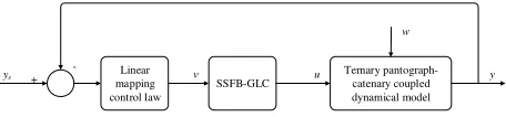
Summary, according to the ternary pantograph-catenary, which also coupling with the dynamics model of the state feedback linearization of the pantograph-catenary system global linear optimal active control strategy as shown in Figure 2.
Linear mapping control law
SSFB-GLC
Ternary pantograph-catenary coupled dynamical model
-+ v u
w
y ys
Figure 2. Globally linear control strategy for feedback- linearization based pantograph-catenary system based on ternary pantograph-catenary coupled dynamical model
According to the formula (30), and the relative order of the system is r=4, the closed loop transfer function of the system is:
( )
( )
(
)
4
0
5 3 4 2 3 1 2
4 4 4 4 4
1
p i
p i
sp
K s K y s
K K y s
s s s s s
µ
µ
µ µ µ
µ µ µ µ µ
+ =
+
+ + + + +
(31) The characteristic equation of the system is composed of the formula (31).
0
5 3 4 2 3 1 2
4 4 4 4 4
0
p i
K K
s µ s µ s µ s µ s
µ µ µ µ µ
+
+ + + + + = (32)
For high order systems, usually set a pair of complex conjugate poles s12, determined by the components of complex conjugate poles, which plays a leading role in the system unit step function. As the dominant pole (because the decay rate is the
slowest), the vibration of the pantograph-catenary coupling system can be thought to other away from the imaginary axis poles3, s4, s5 corresponds to the unit step response decay faster, and they only have certain influence during a very short period of time. Therefore, the approximate analysis of the system transition process is carried out. We can ignore the influence of these components on the system transition process, and it can be used as an approximated two order system to solve the unknown parameters based on the performance index.
4. SIMULATION VERIFICATION ANALYSES
In this paper, the state feedback linearization characteristic equation (32) of the pantograph-catenary vibration coupling system is designed to control the system parameters by the analysis of the approximated two order system parameters,
2 1
5% 4
0.1
s n e
t s
ζπ ζ ξ
ζω
− −
= ≤
≈ ≤
(33)
Among them, the ξ and ts refer to the system overshoot and adjusting time; ζand ωn are known as the system damping ratio and undamped natural oscillations in the angular frequency. According to the performance requirements of the system, damping ratio equals to 1. ωn equals to 50. Therefore, the dominant pole placement for conjugate poles lies on the real axis,
2
1,2 n n 1 50
s = −
ζω
±ω
−ζ
= −In addition, the pole s3 should be maintained that the distance from the imaginary axis can not be less than five times that of the conjugate complex poles
s1, s2on the imaginary axis. That is:
3,4,5 1
Res ≥5 Res =5ζωn (34)
Therefore, Chosen s3=s4=s5=-400. And then work out the desired closed-loop characteristic equation of the system
(
) (
2)
3 5 3 45 3 8 2
9 11
50 400 1.3 10
6.025 10 1.15 10
7.6 10 1.6 10
s s s s
s s
s
+ + = + ×
+ × + ×
+ × + ×
Let the µ4=1×10⁻⁵, then µ3=0.13,µ2=6.025,
1
[image:5.612.63.291.391.444.2]position shows ten times larger than that as the dominant pole distance. Also, Kp =0.32×10⁴, µ0 =7.28×10⁴.
[image:6.612.334.538.41.133.2]In this paper, we choose the active establishment of global linear controller compared with the better , comprehensive performance LQR optimal controller in literature [2, 8]. Also, the method we used is analysis and simulation by MATLAB/Simulink, under the setting of the locomotive running speed equals to 250km / h, the pantograph parameters such as table 2 can be shown below.
Table 2. Typical parameters for pantograph.
Equivalent mess mi
Equivalent damping ci
Equivalent stiffness ki
Heads 6.4 100 2650
Upper
frame 7 100 10000
Lower
frame 12 70 0
[image:6.612.66.285.200.275.2]For the LQR optimal control, the optimal state weighting matrix and the control force weight coefficients are obtained by the empirical method as shown in table 3.
Table 3. Parameters for LQR optimum control.
Parameter Value
State weighted
matrix Q [500,100,500,100,500,100]
Control force weight coefficient
R
0.01
Considering the influence of pantograph and contact wire wear which caused by that the pantograph-catenary contact pressure is too high. Due to, the state feedback linearization of the global first active control (SFL-GLC) strategy, it is obvious to set target contact pressure values as the desired static contact pressure 70N, according to those above, we can gain the waveform graphs combining with the simulation of LQR optimal control strategy proposed in this paper, the state feedback linearization global linear active control strategy of the pantograph-catenary contact force and control strategy of superposition control. This can respectively be shown in Figure 3 and Figure 4.
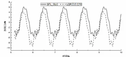
Figure 3. Curves of contact force under different controllers.
Figure 4. Curves of superposed control force under different controllers.
[image:6.612.72.283.362.427.2]Figure 3 shows that compared with the uncontrollable situation, the active control strategy of LQR optimal control strategy and the proposed state feedback linearization based on global linear (SFL-GLC) the fluctuation range of contact force has been reduced. At the same time the mean value of static contact force maintains 70N. However the dynamic fluctuation ratio for SFL-GLC control strategy under the contact pressure is much smaller than that in LQR the optimal control strategy. Besides, from the perspective of statistics, according to the above parameters, in order to get further information, the two control strategies have been simulated in the 300km/h, 250km/h and 200 km/htrain. The results of simulation study on contact pressure have been already shown in Table 4 which lists the pantograph under different control strategies, different speed, maximum and minimum value the average value and standard deviation.
Table 4. Statistical comparison of controlled contact force.
Control strategy
Train speed 300km/h Max.
value
Min. value
Averag e value
Standard deviation Optimum
control 97.04 42.57 68.04 13.55
SFL-GLC 91.66 51.28 70.10 9.325
Control strategy
Train speed 250km/h Max.
value
Min. value
Averag e value
Standard deviation Optimum
control 95.03 44.02 68.17 12.34
SFL-GLC 85.78 54.39 70.06 7.417
Control strategy
Train speed 200km/h Max.
value
Min. value
Averag e value
Standard deviation Optimum
control 92.68 46.01 67.86 11.33
[image:6.612.324.544.429.620.2] [image:6.612.72.284.628.723.2]reach the expectations of requirements as well. In further, this result can validate the purpose of the control strategy in this paper has much more superiority of the LQR optimal control.
5. CONCLUSIONS
In this paper, we firstly establish the ternary pantograph-catenary coupling dynamics model, and then come out the introduction of vibration of the pantograph-catenary coupling system state feedback linearization method, on the basis of this, also, design the effective pantograph-catenary system global linear active control strategy. Compared to the existing active control strategies (such as LQR optimal control, synovial variable structure control, and fuzzy control), this new strategy which based on the state feedback linearization of the pantograph-catenary system global linear active control strategy mainly has the following advantages:
(1) Control strategy is proposed in this paper which binding state feedback linearization design and including linear tracking controller of the closed-loop system transfer function, can vary and design the parameters through the classical zero pole placement control theory. The designed parameters effectively overcome the active control strategy of key parameters, and the dependence of the design experience and knowledge accumulation;
(2) Through performance comparison with better comprehensive performance of LQR optimal controller, the control strategy which proposed in this paper, the standard difference have been reduced by 31.18% and 39.89% and 32.92% under the pantograph-catenary contact force, also, it is possible to achieve a more effective expectations for tracking mean values of the pantograph-catenary contact pressure, and this shows that it has good prospect of Engineering application.
During the control design strategy, the author ignores the equivalent white noise processing of EMU on the excitation effect of pantograph, however, in order to pantograph active control the further development of the foundation of more good foundation. It is necessary to consider the excitation effect of decoupling control in the subsequent global linear control strategy during the process of optimization.
REFERENCES
[1]Yang Gang. Active and Semi-active Control for
Pantograph-Catenary System [D]. Chengdu: Southwest Jiaotong University, 2013.
[2] Lu Xiaobing, Liu Zhigang. Applicability of Active Control Algorithms for Pantographs of High-Speed Railway
[J].Journal of Southwest Jiaotong University, 2015, 50(2):233-240.
[3] Tieri R. Innovative Active Control Strategies for
pantograph-catenary interaction [D]. Stockholm: Royal Institute of Technology, 2012.
[4] Wu Y., Zheng J. H, Zheng T.Q. Optimizing active control scheme of high-speed pantograph[C].IEEE 6thInternational Power Electronics and Motion Control Conference, Wuhan, 2009:2622-2626.
[5] Yang Gang, LI Fu. Sliding mode semi-active control for
high-speed pantograph [J].Journal of Southwest Jiaotong
University, 2013, 48 (1):10-16.
[6] Huang Y.J. Discrete fuzzy variable structure control for pantograph position control [J]. Electrical Engineering, 2004, 86(3): 171-177.
[7] Pisano A, Usai E. Contact force regulation in wire-actuated pantographs via variable structure control and
frequency-domain techniques [J].International Journal of Control,
2008, 81(11):1747-1762.
[8] Lu Xiaobing, Liu Zhigang, Song Yang. Analysis and Verification of Pantograph Active Control based on MR
Damper [J].Chinese Journal of Scientific Instrument, 2015,
36(1):103-109.
[9] Kar Akose E, Gencoglu M T. Adaptive fuzzy control
approach for dynamic pantograph-catenary interaction[C].
Proceedings of 15th International Conference on
Mechatronics, Prague, 2012:1-5.
[10] Wu Yang. Research on Dynamic Performance and Active
Control Strategy of High-Speed Pantograph-Catenary System [D].Beijing: Beijing Jiaotong University, 2011. [11] Allota B. Pugi L, Bartolini F. An active suspension system
for railway pantographs: the T2006 prototype [J].
Proceedings of the Institution of Mechanical Engineers, Part F: Journal of Rail and Rapid Transit, 2009,2 23(1):15-29.
[12] Pisano A. Usaie..Contact Force Estimation and
Regulation in Active Pantographs: An Algebraic Observability Approach[C].46th IEEE Conference on Decision and Control. New Orleans: IEEE, 2007:4341-4346.
[13]Cheng Wei. Research on the Current-collecting Traits of
Electrified Railway’s Pantograph-Catenary System [D]. Chengdu: South west Jiaotong University, 2007.
[14] Michael A, Henson, Dale E. Seborg. Critique of Exact Linearization Strategies for Process Control[J] .Journal of Process Control, 1991, 1(3):122-139.
[15] W.K. Na, B. Gao. Feedback- Linearization-Based
Nonlinear Control for PEM Fuel Cells [J]. IEEE Transactions on Energy Conversion, 2008, 23(1):179-190.
[16] Shuai Dingxin, Xie Yunxiang, Wang Xiaogang. Optimal