1 INTRODUCTION
Global Positioning System (GPS) by satellite has been widely used in outdoor localization due to signal attenuation by the building fabric [1], but it does not work well at all in an indoor environment. Wi-Fi, Bluetooth and radio-frequency location system can be used in indoor low precise localization. The application of Impulse Radio-Ultra Wideband (IR-UWB) has some advantages to achieve the indoor high precise localization by sensors [2]. HDR-UWB (High Data Rate UWB) uses MB-OFDM (Multi Band - Orthogonal Frequency Division Multiplexing) to transmit signals, which can reach a data rate of 200 Mbit/s.
Time-of-arrival (TOA) and angle-of-arrival (AOA) measurements play an important role in positioning systems that employ impulse radio IR-UWB signals. TOA or TDOA of ranging frame are widely used because TOA and TDOA provide high accuracy due to the high time resolution with high bandwidth of IR-UWB signal. TOA and TDOA methods localization is through sending and receiving the signals to measure distance. But AOA is different from that which localizes through measuring the angle information of sending and receiving signals. While even relatively simple receivers can measure TOA with high accuracy, it is much more complex to have precise AOA measurements [3].
In daily communication, UWB with its special advantages can realize high quality and high transmission data, but the power of UWB seriously affects the transmission distance. Therefore, the use of UWB for signal transmission is more suitable for
personal area network. Although the existing positioning algorithm is comparatively mature, but in many field environment, it is not good to use UWB technology to achieve precise positioning and it’s hard to carry out. For example: TOA [4] (Time of Arrival) algorithm for positioning should keep the anchor and the mobile tag absolute clock synchronization. TOF (Time of Flight) [5] location method has a key constraints the sender and the receiver require high precision timer. TDOA (Time Difference of Arrival) requires locations between anchors to keep strict clock synchronized and positioning will be affected if two regions of the clock are out of synchronization. So, how to resolve these problems becomes the target of this research. We will choose TOA cooperate with AOA algorithm to achieve multipoint accuracy positioning.
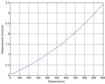
In this paper, we are concerned with IR-UWB localization in relatively large LOS environments making use of simultaneous TOA and AOA measurements. TOA using the IR-UWB signal not only offers high precision location information, but also the low calculated amount. It is suitable for sensors to localize. But in multiple targets case, because TOA based on distance, the direction information is not provided. That may cause miss localization in some special situations. Using TOA association with AOA, there are less miss localization and more precision localization. For complicated environment, details of the theory on TOA algorithm is given, followed by an error analysis mainly on propagation and clock drifts. A 500 MHz experimental UWB localization system was built. The smallest TOA measurement error is
2016 6th International Conference on Information Technology for Manufacturing Systems (ITMS 2016)
ISBN: 978-1-60595-353-3
Research on Multipoint Positioning Based on TOA Cooperate with
AOA Location Algorithm
Dong
Fang, Shen Chong*, Gao Qian
Hainan University, Haikou, China
around 14 cm and the worst error is around 28cm, as was shown by the test results.
2 SIGNAL MODEL
FCC (Federal Communications Commission) had defined the UWB. IR-UWB signal has the properties which are Strong anti-jamming performance, high transmission rate and large capacity of system. The advantages are shown by Fig. 1 while using in indoor localization.
Figure 1. Advantages of IR-UWB.
High accuracy indoor localization requires the system with a high temporal resolution. That can be realized by using pulse signal. The duration of the pulse signal in time domain is extremely short. Supposing the bandwidth of UWB signal is 0.1ns, then localization accuracy can achieve 3cm in theory. Besides UWB signal belongs high-frequency signal, it is less influence of multipath effect. Smaller distortion rate can ensure the high localization accuracy of measurement. Different from common carrier signal, UWB signal does not have carrier wave. With the addition of the characteristics of low power, it is amazing to found there is small interference between UEB and other signals.
IEEE 802.15.4a has given the power, frequency and channel about UWB. In [6], [7], it has described the IR-UWB signal in Mathematical model. The signal that tag transmits can be expressed as follow:
( ) i ( s)
i
s t a w t iT
∞
= −∞
=
∑
− (1)Where ω(t) is an ultra-short monocycle of duration TS, 1/TS is the pulse rate, {ai}are the data
symbols taking values ±1.
We use the channel with the standard IEEE 802.15.4a, the received signal at the nth element can be represented as follows:
1
, , 0 0
( ) s ( ) ( )
M Ln
n i n l s n l n
i l
r t a b p t iT τ n t
−
= =
=
∑ ∑
− − +(2) Where p(t) is single UWB impulse signal; ai is
the i th transmitted symbol taking values ±1;Ln is
the number of multipath at element n; bn,l and τn,l is
the amplitude and delay of the lth multipath signal at element n respectively; TS is the pulse period; nn(t) is additive white Gaussian noise(AWGN) at
element n with zero-mean and N0/2 double sided
power spectral density. τn,l represented the direct
path signal delay which is the TOA for element n, we set it τn for short.
3 LOCALIZATION ALGORITHM
TOA localization algorithm is based on TOA circumference equation, through the different combination of intersecting lines between circle and circle, construct different positioning equation [8]. Shown by Fig. 2.
Anchor AnchorAnchor Anchor1111 Anchor Anchor Anchor Anchor2222 Anchor AnchorAnchor Anchor3333 Tag Tag Tag Tag
Figure 2. TOA location principle diagram.
From the geometry model, assumed the signal transmit from tag to anchors in LOS. The measured distance is di:
2 2
( ) (y ) , 1, 2,3
i i t i t
d = x −x + −y i=
(3)
(Xi,yi)is the NO.i anchor’s coordinate, (xt,yt) is
coordinate of tag.
Then the tag must be located on the circumference of a circle with radius di centered on the anchor. When there are three anchors’ coordinates, TOA measurement equation can be expressed as follow:
2 2 2 2 2 2 2 1 2 1 2 2 1 1 1 2
1
( ) ( ) [(x y ) (x y ) ( )]
2
t t
x −x x+ y −y y= + − + +d −d
(4)
2 2 2 2 2 2 3 2 3 2 3 3 2 2 2 3
1
( ) ( ) [(x y ) (x y ) ( )]
2
t t
x −x x+ y−y y = + − + +d −d
(5) Simultaneous equations, we can calculate the coordinates of the tags:
2 1 3 3 2 1
3 2 2 1 2 1 3 2
( ) ( )
[(x x )(y y ) (x x )(y y )]
t
y y D y y D
x = − − −
− − − − −
(6)
2 1 3 3 2 1
3 2 2 1 2 1 3 2
(x ) (x )
[(y )(x ) (y )(x )]
t
x D x D
y
y x y x
− − −
=
− − − − −
Where:
2 2 2 2 2 2 1 2 2 1 1 1 2
1
[(x y ) (x y ) ( )]
2
D = + − + + d −d
(8) 2 2 2 2 2 2
3 3 3 2 2 2 3
1
[(x y ) (x y ) ( )]
2
D = + − + + d −d
(9) TOA does well in terms of location and distance measurement, but failure in the direction of information. AOA use the angle of the received signal to locate. Anchor can calculate receiving labels angle by the received signal. Extension cord at the receiving point of view, two such extensions of the coordinates of the intersection is the tag.
From Fig. 3, receiving labels angle can be expressed as following:
Tag TagTag Tag
Anchor Anchor Anchor
[image:3.612.348.532.201.329.2] [image:3.612.59.258.243.380.2]Anchor1111 AnchorAnchorAnchorAnchor2222
Figure 3. AOA location principle diagram.
0 0
tan( ) i , 1, 2
i
i
x x
i
y y
θ = − =
−
(10) There is a simulation of AOA location. Setting the angle between the tag and the anchor are respectively 37°, 108°, 167°. The result is this:
Figure 4. AOA simulation results.
The calculated angles are 37.0071°, 107.9969° and 166. 9823°.
4 MULTIPOINT POSITIONING BASED ON UWB INDOOR LOCATION SYSTEM 4.1 The Principle of multipoint positioning
Using only one anchor to locate one tag by TOA cooperates with AOA can be achieved in our experiment. But the key research content of Multipoint Positioning is to realize large capacity multi-label real-time accurate positioning. The positioning range of a base station is limited. TOA
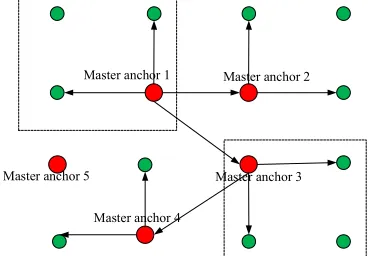
algorithm for positioning should keep the anchor and the mobile tag absolute clock synchronization. So, the premise of multipoint positioning is to ensure clock synchronization between the various regional networks. However, the difference between LAN (Local Area Network) environments is difficult to achieve clock synchronization. This paper studies the relative clock synchronization of master anchors and tags in different regions based on TOA/AOA algorithm. Namely, all the anchors and tags in the area have been relative clock synchronization. The principle diagram was shown in Figure 5.
Master anchor 1 Master anchor 2
Master anchor 3
Master anchor 4 Master anchor 5
Figure 5. LAN of master-slave clock synchronization.
We set multi-master anchors at first and they are responsible for sending the clock synchronization information to the corresponding slave anchors. The tag will send the data information and clock synchronization information to the anchors. The clock signal sent by the master anchor 1, clock synchronization information from the master anchor 1 will be received by the slave anchors and the slave anchors adjust its clock signal to ensure network clock synchronization. Show in Figure 5, the master anchor 2 in the intersection of the two areas of the network will send the clock synchronization information which receives from master anchor 1 separately to the adjacent area network like master anchor 3. Each anchor and tag has its own ID. It will have a delay, but this does not affect the real-time precise positioning of tags in the respective area network. From the above principle: relative clock synchronization of multiple LAN ensures multipoint positioning to achieve.
4.2 Selection of anchor location
In our experiment, the anchor location is fixed. Due to the receiver noise in each anchor and errors associated with multipath and signal shadowing effects, delay of clock, there will be errors in the measurement of localization. GDOP provide guidance to the design of short to medium-range outdoor and indoor locating systems [9]. At the same time, [10] put forward the analysis of GDOP is an essential feature in determining the performance of a positioning system. At the same time, [11] put forward that the accuracy of a position estimate can be expressed as the product of the GDOP at a point and the root-mean-square error (RMSE) of the ranging errors from anchors to the moving tag. When the time error is definite, the GDOP value is higher resulting in poorer positioning performance while the GDOP value is lower resulting in higher positioning performance. For a system, the GDOP effect can become the dominant factor in limiting the positioning performance if the location and number of anchors in the monitoring area are not carefully planned.
So, when we set up the anchor and the selection of the master anchor, we will take this factor into account. And the algorithm priority selects the master anchor with high coordinate. Because the higher the coordinates, the higher the probability of the obstruction, the higher the accuracy of the positioning. The location of the anchors will followed the next rules:
1) One anchor will be located at the end of each straight of the track, for a total of four anchors.
2) The location of the anchor will be different in Z label.
3) The master anchor will be in center. This location is appropriate for a master anchor to control all the other slave anchors.
5 THE TEST DATA
Essentially, the followed tests have been done by HN-EVK1000 in a rectangular laboratory which is 6.8m*12.6m. We can visually observed results of the tests on our system client.
[image:4.612.344.522.88.231.2]First, using only one anchor to locate one tag by TOA cooperates with AOA. The test data are show by Fig.6.
Figure 6. Display of one anchor and one tag.
In Fig.6, the blue point stands for anchor, the red one is tag. Compared the located results with the true location, error is 0.0867m.
Figure 7. Data of one anchor and one tag.
[image:4.612.360.511.332.434.2]For multipoint positioning, we need test in NLOS. Figure 8 is the locating trajectory which displayed on a panel computer. The blue dots represent four anchors and the red dot represents mobile tag. The yellow dot is the moving track of the tag.
Figure 8. Client display.
Consider a localization system defined by the geometry of a mobile tag and anchors. The true position of the mobile tag is at the origin of the coordinate system. And in our experiment, we used localization error to measure the performance of the positioning system which is shown in Figure 10 and Figure 11. In this study, we used only one mobile label. Localization error is defined as follows:
2 2 2
eL= (x−x) +(y−y) +(z−z)
(11) Where eLis the localization error, ( , , )x y z is the Tag’s measurement coordinate location and
[image:4.612.343.531.615.726.2]( , , )x y z is Tag’s actual coordinate location.
Figure 9. Experimental environment.
[image:4.612.79.260.635.732.2]20 m 10.5m 3m× × show in figure 9. Anchor1 and
Anchor5 are the master anchors. We used 6 anchors in our experiment and TOA cooperate with AOA algorithm is used. Two coordinate axes are established in the experiment, and the anchor coordinates are fixed. We tested 20 positions and each position test 60 times per second. Figure 10 is the histogram of statistical 60 times. We set two master anchors at first and they are responsible for sending the clock synchronization information to the corresponding slave anchors.
15 16 17 18 19 20 21 22 23 24 25 26 27 28
0 5 10 15
N
u
m
b
e
r
o
f
lo
c
a
liz
a
ti
o
n
e
rr
o
r
Localization error/cm
Figure 10. Histogram of number of localization errors of per one testing.
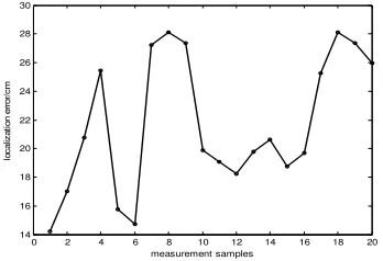
Figure 11 is a simulation diagram about multipoint positioning. From the figure, we can see that the positioning accuracy keeps in 15-28cm.
0 2 4 6 8 10 12 14 16 18 20
14 16 18 20 22 24 26 28 30
lo
c
a
liz
a
ti
o
n
e
rr
o
r/
c
m
measurement samples
Figure 11. Location error for multipoint positioning.
6 CONCLUSIONS
In this paper, we researched on multipoint positioning based on TOA and AOA location algorithm. In our experiment, we used a single anchor to locate a tag, this method is suitable for small range of localization. And in order to maintain the higher localization accuracy, it is necessary to set more anchors in other places to expanding the scope of the positioning. TOA algorithm for positioning should keep the anchor and the mobile tag absolute clock synchronization, so we used the way of relative clock synchronization to achieve multipoint positioning in large area. From the test result, we can clearly see the localization performance achievable in different scenarios. The accuracy for using a single anchor to locate a tag showed excellent agreement because multipoint
positioning exist the problem of clock synchronization.
In our future study, we will study how to reduce the power consumption of tags and multi-label positioning and more absolute clock synchronization problems will be researched in our experiment.
7 ACKNOWLEDGMENT
This work was tested by HN-EVK1000 in the Hainan University. This work was supported by National Natural Science Foundation of
China under Grant No. 61461017.
[image:5.612.88.256.175.289.2]This is an anchor of HN-EVK1000 as Fig.12 and working state as Fig.13.
[image:5.612.337.534.237.580.2]Figure 12. Anchor of HN-EVK1000.
Figure 13. Working state of snchor.
This is a tag of HN-EVK1000.
Figure 14. Tag of HN-EVK1000.
REFERENCES
[1]Wang, E., Zhao, W., & Cai, M. “Research on improving accuracy of GPS positioning based on particle filter.” In Industrial Electronics and Applications (ICIEA), 2013 8th IEEE Conference on, pp. 1167-1171.
[image:5.612.87.261.366.485.2]feasibility study.” Sensors Journal, IEEE, vol.12, pp.1649-1659, Jun 2012.
[3]Taponecco, L.; D'Amico, A.A.; Mengali, U., “Joint TOA and AOA Estimation for UWB Localization Applications,” IEEE Transactions, on Wireless Communications, vol.10, pp.2207-2217, July 2011.
[4]He J, Li S, Pahlavan K, and Wang, Q, “A realtime testbed for performance evaluation of indoor TOA location
system,” IEEE International Conference on
Communications, 2012, pp. 482 – 486.
[5]Dong Z, Wu Y, Sun D, “Data Fusion of the Real Time Positioning System Based on RSSI and TOF,” IEEE International Conference on Intelligent Human-machine Systems & Cybernetics, 2013, pp. 503 – 506.
[6]Kietlinski-Zaleski, J., Yamazato, T., & Katayama, M. “TOA UWB position estimation with two receivers and a set of known reflectors.” In Ultra-Wideband, 2009. ICUWB 2009. IEEE International Conference, pp. 376-380 [7]Zhu, S., Sun, F., & Chen, X. “Joint UWB TOA and AOA estimation under 1-bit quantization resolution.” In
Communications in China (ICCC), 2013 IEEE/CIC International Conference, pp. 321-326.
[8]D'Amico, A., Mengali, U., & Taponecco, L. (2010). “TOA estimation with the IEEE 802.15. 4a standard.” IEEE Transactions. on Wireless Communications, vol.9, pp. 2238-2247, July 2010.
[9]Sharp, I., Yu, K., & Guo, Y. J. (2009). GDOP analysis for positioning system design. Vehicular Technology, IEEE Transactions on, 58(7), pp. 3371-3382.
[10] Shen, Y., & Win, M. Z. (2010). Fundamental limits of Wideband Localization—Part I: A general framework. Information Theory, IEEE Transactions on, 56(10), pp. 4956-4980.
[11] Abbasi A, Kahaei, M H, “Improving source
localization in LOS and NLOS multipath environments for UWB signals”. In Computer Conference, 2009. CSICC 2009. 14th International CSI. IEEE, 2009, pp. 310 -316.