2016 International Conference on Manufacturing Science and Information Engineering (ICMSIE 2016) ISBN: 978-1-60595-325-0
Comparative Analysis of Meshing Performance
of Spiral Bevel Gears Generated by Duplex
Helical and SGM Method
GUOBING HUANG, HONGZHI YAN, ZHIAN HU, MENG XIAO
and TENGFEI ZHOU
ABSTRACT
In order to get a deeper understanding of duplex helical method, the mathematical model of spiral bevel gear pair by duplex helical method was established and two models of gear pairs generated by duplex helical method and SGM method respectively were built for meshing performance analysis. The duplex helical method for pinion generating was introduced in detail through the process of the pinion modeling. The meshing performance of the gear pairs modeled was analyzed by finite element analysis software. The results show that the meshing performance of the gear pair by SGM method is superior to that by duplex helical method. The contact pressure, contact force and transmission error of the gear pair by SGM method are preferable while severe edge contact happens to that by duplex helical method and its contact path is discontinuous. For duplex helical method, tooth modification should be done to get better meshing performance.1
INTRODUCTION
Spiral bevel gear drive is an important transmission type that is widely used in cars, ships, aircrafts and other mechanical equipment for its high transmission performance. The contact area and transmission error of the gear drive play an
1Guobing Huang, Hongzhi Yan, Zhian Hu, Meng Xiao, Tengfei Zhou, State Key Laboratory
important role on the working performance and life of the equipment. Thus, studying on the meshing performance of spiral bevel gear and to improve it are important.
Five-cut process and duplex helical method are two widely used cutting methods brought forward by Gleason. For five-cut process, the gear, cut by a roughing cutter after a finishing cutter, can be generated by generated method or formate method and the pinion, cut by an alternate blade roughing cutter after a finishing outer blade cutter and a finishing inner blade cutter, can be generated by tilting method or modified roll method. The concave side and the convex side are cut individually in five-cut process.
In 1987, Shtipelman [1] introduced the cutting principle of the five-cut process in detail for the first time. Litvin [2, 3] developed an approach to calculate the machine-tool setting of the pinion based on local synthesis theory. Xutang Wu [4], Cheng Chanqi [5], Xuezhu Dong [6] et al. did a serious of researches on the five-cut process including cutting principle, calculation of machine-tool settings of different kinds of machines and tooth contact analysis (TCA).
As for duplex helical method, the surfaces of the pinion or the gear are finished by an alternate blade cutter (with outside blade followed by inside blade and next outside blade and so on) at the same time [7].The gear can be cut by generated or formate method and the pinion must be finished by duplex helical method. Wang Zhe, Liu Qingmin et al.[8-12] introduced the exact duplex helical method about the blank design, the determination of machine settings and calculating point. TSAY and LIN et al.[13, 14] established the mathematical model of the spiral bevel and hypoid gears using duplex helical method. ZHANG Yu, YAN Hongzhi et al. [15] established the mathematical model of spiral bevel and hypoid gears by half-formate duplex helical method and proposed a new method of TCA.
SPIRAL BEVEL GEAR MODELING
Coordinate systems and equations of pinion tooth surfaces
For duplex helical method, the gear can be produced by generating method or formate method. SGM and formate method are clearly described in [16] and is not presented in this paper.
In duplex helical method, the generating gear spins about its axis and moves along the axis at the same time. Figure 1 shows the generating coordinate systems of the pinion. The coordinate system σ1(x01, y01, z01) is fixed on the cutting machine
with O01 located in the machine center and plane x01O01y01 lying on the machine
plane. O1 is the cross point of the pinion. Ot1 is the center of the cutter. E1,j1,i1, δM1,q1,S1,X1and XB1 are the machine-tool settings and their meaning can be found in
the succeeding TABLE II. Unit vector p⃑⃑⃑ 1represents the axis of the pinion. The coordinate system σ2(xt1, yt1, zt1) is a stationary system with zt1 axis coincident with
a) Cutter installment b) Pinion installment
Figure 1. Pinion generation coordinate systems.
As shown in Figure 1 a), the cross section of the cutter is a line segment. In σ2,
when the cutter rotates with an angle θ1, the point M on it can be expressed as:
1 1 1
1 1 1 1 1 1
1 1
( sin ) cos
( , ) ( sin ) sin
cos
g
t g
r u
r u r u
u (1)
Whererg r0 Wb1 2(r0 is the nominal radius and Wb1 is the point width of the
cutter) is the radius of the tool nose; u1 is the distance between point M and the tool nose; α1=α01 (for outside blade) or α1=αin1 (for inside blade) is the blade angle.
The unit normal at M is represented by the equation:
1 1
1 1 1 1
1 1 1 ( , ) t t t t t r r u n u r r u (2)
1( ,1 1)
t
r u and n ut1( ,1 1) can be expressed in σ1 as:
1( ,1 1) 1( ,1 1)
o ot t
r u M r u (3)
1( ,1 1) 1( ,1 1)
o ot t
n u M n u (4)
Where matrix Mot is the coordinate transformation matrix from σ2 to σ1. When generating the pinion, the cradle rotates with respect to the axis z01. The
moving surface of the spinning cutter profile is the generating surface. Assume that the cradle rotates ∆q1 from the initial position, it translates along its axis
simultaneously because of the screw mechanism. The displacement is H1∆q1 (H1 is
normal vector are:
1( , ,1 1 1) 1( , )1 1 0 0 1 1
T s o
r u q M r u H q (5)
1( , ,1 1 1) 1( , )1 1 0 0 1 1
T s o
n u q M n u H q (6)
Where
1 1
1 1
cos sin 0
sin cos 0
0 0 1
s
q q
M q q
.
The angle that the pinion goes through from the initial position is 1 i01 q1 and
i01 is the ratio of roll. Assume that the generating gear rotates about its axis z01 uniformly with unit angular velocity which means ∆q1=t, the angular velocity of the work piece is:
1 01 d i dt (7)
The angular velocity and velocity of the generating gear relative to the work piece are:
12 k i p01 1
(8)
12 12 1 01 1 1
v r i pm (9)
Where k is the unit vector of z01 axis, p1 cosM1isinM1k and m1O O1 01
(see Figure 1).
From the meshing equation v12 n1 0 and Eq. 5, the meshing equation can be
written by the form as:
1 1 1
( , , ) 0
f u q (10)
The points on tooth surface must satisfy Eq. 10. Analytical solution of Eq. 10 cannot be found since there are three variables. However, it is possible to obtain the numerical solution in a certain range by using iteration algorithm.
Establishment of 3-Dimensional Model of the Gear Pair
Every set of numerical solution of Eq. 10 can help find a point by substituting them for the variables in Eq. 5. However, without knowing the ranges of u1, θ1 and
∆q1 beforehand, the point may be out of the tooth surface. Therefore, a changing
coordinate system σ3{O,L,R} is established as Figure 2 shows to be the transitional
1 | 1 1|
R r p (11)
1
1 1
L r p
(12) Values of L1 and R1 are known from the blank parameters. Combining Eq. 10 to
Eq. 12 and varying L1 and R1, the corresponding points on tooth surface can be
calculated by programming
Figure 2. Transitional coordinate system for pinion. Figure 3. Gear pair by duplex helical method.
[image:5.612.107.490.468.599.2]Using the discrete points, a series of spline curves that are fitting the tooth surface can be got in the CAD software. Figure 3 shows the assembly model of the gear pair by duplex helical method. The major parameters of the gear pairs and the machine-tool settings are listed in TABLE I and TABLE II.
TABLE I. MAJOR PARAMETERS OF THE GEAR PAIR.
Notation Pinion Gear Pinion Gear
Cutting method Duplex Formate Modified roll Generated
Number of teeth z1,z2 15 47 15 47
Module (mm) m1,m2 8 8 8 8
Shaft angle(deg) ∑ 90 90
Face width(mm) b1,b2 50 50 50 50
Pitch angle(deg) γ1,γ2 17.7 72.3 17.7 72.3
Addendum(mm) ha1,ha2 10.13 3.31 10.13 3.31
Dedendum(mm) hf1,hf2 5.03 11.85 5.03 11.85
Hand of spiral LH RH LH RH
Spiral angle(deg) β1,β2 35 35 35 35
1
r
R
L
L1
R1
O p1
TABLE II. MACHINE-TOOL SETTINGS AND INSTALLMENT SETTINGS.
Notation Pinion Gear Pinion Gear
Convex Concave
Cutting method Duplex helical SGM
Cutter diameter(mm) Dt1,Dt2 306.47 304.8 304.8 304.72
Point width(mm) Wb1,Wb2 2.96 4.5 4.32 3.175
Radial distance(mm) S1,S2 151.79 152.04 154.97 147.37 150.99
Tilt angle(deg) i1,i2 16.04 0 0 0 0
Swivel angle(deg) j1,j2 326.95 0 0 0 0
Work offset(mm) E1,E2 1.959 0 -2.54 2.54 0
Machine root angle(deg) δM1,δM2 357.96 67.08 16.24 16.24 68.86
Machine center to cross
point(mm) X1,X2 2.46 5.24 4.20 -4.34 0
Sliding base(mm) XB1,XB2 29.98 0 -1.18 1.21 0
Ratio of roll i01,i02 3.196 0 3.33 3.25 1.05
Helical motion-1st order H1,H2 11.08 0 0 0 0
MESHING PERFORMANCE ANALYSIS
Finite Element Modeling
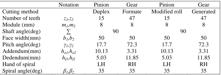
Spiral bevel gear has so complex geometrical structure that it is hard to directly build its finite element model in finite element analysis (FEA) software. Therefore, an import of the solid model into the FEA software and meshing it afterwards is adopted. The FEA of spiral bevel gear is non-linear, which often takes much more time of calculation than that of a linear one. In order to improve the calculating efficiency, a simplified FEA model of seven teeth, which ensures the efficiency and enough data at the same time, is used for the analysis as Figure 7 shows.
Figure 7. Seven-teeth FEA model of spiral bevel gear.
The pinion is set to be the driving gear and the gear to be the driven one as they are in most cases. For the pinion, the drive side is concave and the coast side is convex. The magnitude of the moment applied to the gear as the load is 300Nm. The gear and the pinion are only allowed rotating around their own axis.
[image:6.612.258.349.474.550.2]TABLE III. GEAR MATERIAL’S PROPERTIES.
Material Type Young’s Modulus
(GPa) Poisson Ratio
Density (g/cm3)
16Cr3NiWMoVNbE 185 0.3 7.85
The two models share the same structure and settings in FEA.
Finite Element Analysis Results
The simulation processes show that the gear pairs have very different meshing performances. The duplex helical one has one to three pairs of teeth are meshing at the same time while the SGM one has one to two pairs. The gear pair by duplex helical method has unfavorable meshing behaviors.
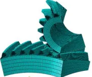
a) Duplex helical
b) SGM
a) Duplex helical b) SGM Figure 9. Mises stress of the pinions.
Figure 8 a) and b) show the contact pressure contour plots of the fourth tooth surfaces of the pinions and Figure 9 a) and b) show the Mises stress. The maximum Mises stress of the pinion by duplex helical method is 694MP and it is 2 times bigger than that of SGM. The contact pressure contour plots in temporal-order moments are drawn from bottom to top. In each figure, the first plot represents the moment that the tooth just begins meshing in and the last plot happens at the time the tooth is meshing out. Apparently, the contact area of the gear pair by duplex helical method is not a continuous one and the contact happens mostly at the root or the top of the gears which behave as severe edge contact. The maximum contact pressure is about 1500MPa. As for the gear pair by SGM method, the contact area is acceptable. The maximum contact pressure during meshing is about 314MPa, happening at the moment meshing-in which indicates a slight stress concentration on the tooth crest of the gear.
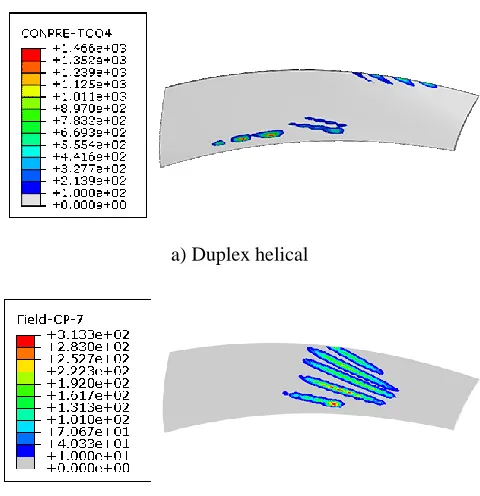
[image:8.612.120.477.464.615.2]a) Duplex helical b)SGM
Figure 10. Contact force of teeth surface.
periodicity. The dash lines in a) and b) are the composite forces of contact which show that the composite forces of the two models are similar and the maximum is about 2450N. From figure 10 a), each curve is made up of two parts: a major part and a minor part. The major one is ahead of the minor one and the maximum of the major one is approximately twice as big as that of the minor one. Between these two parts, the contact force is zero which means the tooth is not contacting and this mostly happens when the next contact teeth pair are meshing alone. Figure 10 b) shows that single tooth meshing and double teeth meshing are conducted alternatively.
[image:9.612.114.470.302.436.2]From reference [18], contact ratio can be written as ε= T T⁄ 1 as Figure 10 a) shows. Although the meshing performance is not favorable, the gear pair by duplex helical method has a higher contact ratio (2.47) than that of the gear pair by SGM method (1.35).
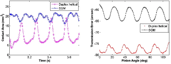
Figure 11. Contact Area. Figure 12. Transmission Error.
Figure 11 shows the contact area curves with respect to time. The figure indicates that the contact area of the gear pair by SGM method is larger than that by duplex helical method on the whole. The average contact area is 19.7 mm2 and 9.6 mm2 respectively. With smaller contact area, the contact pressure is much bigger as mentioned above.
CONCLUSIONS
This paper presents the modeling of the spiral bevel gears generated by duplex helical method and gives the comparative analysis of the gear pairs by duplex helical method and SGM method. With two examples of the spiral bevel gear pairs with number of teeth 15×47 generated by duplex helical method and SGM method respectively, the following conclusions can be drawn:
1) The duplex helical method is feasible for spiral bevel gear modeling. The modeling steps are suitable for other spiral bevel gears generated by two-cut method.
2) For the duplex helical method, the maximum contact pressure is about 1500MPa and the maximum contact force of the contact teeth pair is 2450N. For the SGM method, the contact force is similar to duplex helical method because of the same load and similar dimensions but the maximum contact pressure (314MPa) is only about 20% of that of the duplex helical method.
3) Compared to SGM method, the contact performance of the duplex helical method is not favorable though it has higher contact ratio. Severe edge contact and undesirable contact area happened to duplex helical method. In order to get good meshing performance, tooth surface modification must be applied.
4) For both duplex helical method and SGM method, the maximum transmission error (peak-to-peak value) is less than 7 arcsec.
To sum up, the meshing performance of the gear pair by SGM method is better than that by the duplex helical method. Therefore, tooth surface modification is necessary for duplex helical method.
ACKNOWLEDGEMENT
This research was financially supported by the National Science Foundation (51575533) and the National Science Foundation (51375159).
REFERENCES
1. Shtipelman B A. 1978. Design and Manufacture of Hypoid Gears. John Wiley & Sons, Inc. 2. Litvin F L, Fuentes A. 2004.Gear Geometry and Applied Theory. Cambridge University
Press.
3. Litvin F L, Zhang Y, Lundy M, et al. 1988. “Determination of Settings of a Tilted Head Cutter for Generation of Hypoid and Spiral Bevel Gears,” ASME Journal of mechanisms, transmissions, and automation in design. 110(4): 495-500.
4. Xutang Wu. 1981. “Machine-tool Settings of Spiral Bevel and Hypoid Gears Cut by Half-spread-out Tilting,” Machine Tool. (11): 6-17.
5. Cheng Chanchi. 1979. “The Local Conjugate Principle and its Application in the Calculation
for Cutting the Spiral Bevel and Hypoid Gear Tooth,” Journal of Mechanical
6. Xuezhu Dong. 1987. “New Methodology for Machine-tool Settings Calculation of Hypoid Gears Cut by Half-spread-out Modified Roll,” Gear. 11(4): 1-7.
7. Hermann J. Stadtfeld, the Gleason Works. 2014. Gleason Bevel Gear Technology: Basics of Gear Engineering and Modern Manufacturing Methods for Angular Transmissions. Gleason Works.
8. Wang Zhe, Liu Qingmin, Zhang Dejun et al. 1995. “The Exact Duplex Helical Method in Generation of Spiral Bevel Gears (I)──The blank design of the spiral bevel gears,” Journal of Jilin Forestry University. 11(2):75-79.
9. Wang Zhe, Liu Qingmin, Li Qingsheng et al. 1995. “The Exact Duplex Helical Method in Generation of Spiral Bevel Gears (II)──The machine setting of generating the gear of the spiral bevel gears,” Journal of Jilin Forestry University. 11(2):80-82.
10. Wang Zhe, Liu Qingmin, Zhang Dejun. 1995.“The Exact Duplex Helical Method in Generation of Spiral Bevel Gears (III)──The determination of the calculating point and its curvature of the gear surface of the spiral bevel gears,” Journal of Jilin Forestry University. 11(3):138-141.
11. Wang Zhe, Liu Qingmin, Li Qingsheng. 1995. “The Exact Duplex Helical Method in Generation of Spiral Bevel Gears (IV)──The determination of the calculating point and its curvature of the pinion surface of the spiral bevel gears,” Journal of Jilin Forestry University. 11(3):142-145.
12. Wang Zhe, Liu Qingmin, Sun Wancai. 1995. “The Exact Duplex Helical Method in Generation of Spiral Bevel Gears (V)──The machine setting generating the pinion of the spiral bevel gears,” Journal of Jilin Forestry University. 11(4):210-216.
13. Tsay C B, Lin J Y. 1993. “A mathematical model for the tooth geometry of hypoid gears,” Mathematical & Computer Modelling. 18(2):23-34.
14. Lin C Y, Tsay C B, Fong Z H. 2011. “Computer-aided manufacturing of spiral bevel and hypoid gears by applying optimization techniques,” Journal of Materials Processing Technology. 114(1):22-35.
15. Zhang Yu, Yan Hongzhi, Zeng Tao. 2015. “Cutting Principle and Tooth Contact Analysis of Spiral Bevel and Hypoid Gears Generated by Duplex Helical Method,” Journal of Mechanical Engineering. 51(21):15-23.
16. ZENG Tao. 1989. Design and Manufacture of Spiral Bevel Gear. Harbin Institute of Technology Press.
17. Teng Baiqiu, Chang Chunjiang. 2003.“New Material for Aeroengine —
16Cr3NiWMoVNbEGear Steel,” AEROENGINE. 29(2):34-37.