2017 3rd International Conference on Computer Science and Mechanical Automation (CSMA 2017) ISBN: 978-1-60595-506-3
Numerical Calculation of Misaligned Optical
System under Interference Vibration
Jun SHAO
1,2, Jing-Feng YE
2, Zhi-Yun HU
2,Zhen-Rong ZHANG
2and Jing-Yin LI
11School of Energy and Power Engineering, Xi’an Jiao Tong University, Xi’an 710049, China
2
The State Key Laboratory of Laser Interaction with Matter, Northwest Institute of Nuclear Technology, Xi’an 710024, China
Key words: ANSYS, Numerical calculation, Optical misalignment, Transient analysis, Vibration.
Abstract. For the purpose of providing a method to estimate the effect of vibration on ultrasonic combustion engine in laser diagnosis, numerical simulation and experimental technology in this report for misalignment of basic optical system under interference vibration are studied. To provide a method to estimate the effect of vibration on the optical performance of a combustion diagnostic optical system, a numerical calculation method for the misaligned optical system under interference vibration was proposed. With the ANSYS finite element analysis software, the physical model of misaligned optical system under interference vibration was developed and the transient dynamic analysis was inspired by vibration displacement got by sensors .Then dynamic response of the mirror was obtained by transient dynamic analysis. On the basis of the matrix optics, geometrical optics theory and the mechanic vibration theory, the vibration misalignment matrix of mirror was analyzed, and the vibration misalignment model was also built. Meanwhile, the method of simulating calculation of misaligned optical system under interference vibration was inferred. Furthermore, an experiment was carried out to validate the method. The results show that the high precision of the simulation and the relative error of simulation calculation and experimental data can reach at 4.1% and 0.8% in the horizontal and vertical direction. The calculation proves to be highly precise. This research can be used in improving the stability and capability for avoiding vibration of laser diagnostics integrated system in intricacy environment. The numerical method can be used in laser diagnostics application.
Introduction
With the constant development of the optical system in application area, some complicated optical systems move gradually towards real use from the laboratory. However, various dynamical interferers rising in the application environment, such as the mechanical vibration caused by various kinds of reasons, change of environment temperature, turbulent atmosphere and dust fog, affect more or less the performance of the optical system, thus seriously counteract the practicability of the optical system. Unfortunately, it is avoidless that mechanical vibration can influence the imaging quality, measure precision, and the pointing accuracy of target tracking. And it has become the major factor influencing the stability of the optical system in application environment. Therefore, the anti- vibration evaluation of the optical system in application environment proves to be an important research area.
this paper carries out a series of relative research on numerical calculation of luminous transmission in misaligned optical system under interference vibration, and offers certain technological reserve for the application of optical system in combustion diagnostics.
Dynamics Calculation of Physical Model of Misaligned Optical System under Interference Vibration
Modeling of Misaligned Optical System under Interference Vibration
Finite Element Model
In this section, we take the common mirror reflector with mount as our research object and obtain the displacement response under excitation vibration by transient dynamics analysis. Because the main factor of influencing the results of transient dynamics analysis is rigidity and mass distribution, therefore some partial weeny characters (e.g., angle, screw thread etc) can be ignored in real modeling, making sure that the mass distribution of the component and the whole constructive characteristic are not influenced. These partial structures have a very small influence on the results of dynamics analysis [5-9], but have calculation enhancing, thus this kind of simplification is reasonable and economical.
The reflector solid model is chosen as our research object which is set up by Pro/E (product of PTC Co.) according to the blueprint shown in Fig. 1. Fig. 2 illustrates that the finite element model of the reflector is built by ANSYS. We set the element type SOLID92, and material attribute parameters are shown in Tab.1.
Figure 1. Reflector entity model. Figure 2. Finite element analysis model reflector.
Table 1. The list of material attribute parameters.
Components Material Density(g/cm3) Poisson
ratio
Elastic modulus(GPa)
Mirror Quartz glass 2.2 0.15 72
Mirror frame Aluminum alloy 2.82 0.3 74.8
Hander Stainless steel 7.88 0.3 200
Supporting Iron 7.85 0.3 206
Dynamics Analysis of Reflector under Excitation Vibration Power
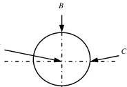
Figure 3. The image of reference points on the mirror plane.
[image:3.612.93.519.166.268.2]
(a) The acceleration in X direction (b) The acceleration in Y direction (c) The acceleration in Z direction
Figure 4. The vibration excitation signals loaded on the model.
(a) The image of point A (b) The image of point B (c) The image of point C
Figure 5. The vibration model changes of the reference point in Z direction.
Calculation the Misalignment Displacement of the Model under Interference Vibration
In this section, we will illustrate the calculation of misalignment model system under interference vibration. Obviously, the deflection angle and offset of the reflector are important parameters to relate the output of vibration misalignment model to the input of luminous transmission model. And under the effect of vibration power, the distortion of the reflector is very small. Fig. 6 shows that the deflection angle of the reflector can be obtained by computing the relative offset of reference points A and B on the reflector. The detailed processes are discussed briefly in the following. First, It is
shown the initial state of reflector γ without any interferer in Fig. 6, which is in coordinates XOY.
Then, at certain time under interference vibration, the projection angle θof reflector γ ′is got in
coordinates YOZ. The angle θ is the deflection angle of the reflector. As observed in Fig. 7, it is
got the geometric image of two points on the perpendicular of reflector surface after vibration
interfering. zA and zBare the initial position of A and B on the Z axis. zA′ and zB′ are the position
of A and B on the Z axis at certain time under interference vibration. Finally, It can be obviously
obtained the deflection angleθ of the reflector at that moment from the following formulas (1) and
(2).
A
B
[image:3.612.89.529.342.467.2]Figure 6. The coordinates of rotational reflector.
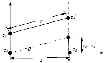
Figure 7. The geometric image of two points on the perpendicular reflector surface after vibration interfering.
As observed in Fig.7, the geometric relation that we can obtain is
tg (zB zA)
r
θ = ′ − ′ (1)
Because the deflection angleθ is very small, it can be simplified that
θ =tgθ (2)
So the deflection angle at certain time and certain coordinates can be computed in dividing the position subtraction of A and B after vibrating by the radius of the reflector. Now the data at 3 s is
taken for instance, z′A =0.4409 µm, zB′=0.5568 µm, , r =25 mm, according to (1) and (2), the
deflection angle θ= 4.6375e-5 rad in coordinates XOY can be obtained.
According to optical theory analysis, the main reasons of causing the angle misalignment of the misaligned light are the deflection angle in left or right and up or down directions, while the reflector is influenced by a weeny motion under vibrating. As it’s known that the projection
deflection angle θ in coordinates YOZ is the deflection angle in left or right direction, and the
projection deflection angle η in coordinates XOZ is the angle in up or down direction, the
projection angle in coordinates XOY can be ignored. Now the data at 3s is also taken for instance,
η
from the vibration response of reference points A and C can be got, which is η=5.4488e-6 rad.
As shown in Fig.5, the offset of reference point A is the offset of output light of the reflector. And
then it is found that ∆zA=5.5688 µm, while input the data at 3 s. Next the modeling and calculation
of ray-tracking model are discussed briefly in the following section 3.
The Modeling and Calculation of the Ray-Tracking Model
Modeling of Ray-Tracking Model
In succession, based on geometrical optics and matrix optics [13-16], we analyze the vibration misalignment transform matrix of optical system in theory, meanwhile, contrapose the transform matrix of three-dimensional misaligned displacement in paraxial optics systems under mechanical vibration. Then, the three-dimensional vibration misalignment model of optical system is established.
[image:4.612.216.396.201.310.2]Now it is supposed the incidence surface of reflector XiOYi and incidence direction of light Zi
are vertical, the output surface Xi*OYi* and output direction Zi* are vertical too, where 2α is the
angle of the incidence surface and output surface, as shown in Fig.8. As observed in Fig.9, the
surface in solid line denotes the reflector surface, the normal-to-line displacement is δn, the
component of rotation angular displacement in reflector surface is εn, and the input angle and
output angle is Φi and
*
i Φ
respectively, p point is the receiving light point on the reflector
surface, whilst the radius vector of input point ri, the normal vector of reflector rn,and the radius
vector of output point ri*, which is supposed to be approximate in the same transmission surface in
paraxial optics systems. And it’s assumed that exi and
*
i
e are the unit vectors in X direction, while
the unit vectors in Y direction are eyi and
*
yi e
. The component of angular displacement in the
surface of reflection is ετi. Upon that, the transform matrix of three-dimensional misaligned
[image:5.612.231.379.420.534.2]displacement expression (3) is proposed.
[image:5.612.139.448.567.618.2]Figure 8. The ray-tracking image of plane mirror.
Figure 9. The image of positional relation between entrance and exit planes.
* *
*
* *
1 0 0 2 cos 0 0
0 1 0 0 2 0
0 0 1 0 0 2 sin
xi i xi i n
yi i yi i yi
xi i xi i i
e r e r
e e
e e τ
α δ ε α ε
⋅ ⋅ −
⋅ Φ = ⋅ Φ + −
⋅ Φ ⋅ Φ −
(3)
In order to calculate the misalignment after S distance transmission in interferer condition, first of
all the input parameters should be fix on, such as the angle of reflector and normal α , the
information of input beam p and output beam q (includes the normal displacement of reflector δn,
y ε
is the component of rotation angular displacement in lens plane, and ετ is the component of
tangential angular displacement in the surface of reflection ). Then, these parameters are input into (3).
According to the inferred transmission matrix formulation, the calculation of ray-tracking is realized by the software of Matlab.
The Calculation of Misaligned Optical System under Interference Vibration
In this section, based on the physical model of misaligned optical system under interference vibration established in ANSYS, and combined with the misaligned ray-tracking model programmed in Matlab, the optical misalignment is calculated. And the deflection angle and offset
of the reflector are input in Section 2.1 into above model. Then we obtain the output 186.45 µm,
which is the distance between the initial light spot and the light spot under interference vibration on the receiving screen.
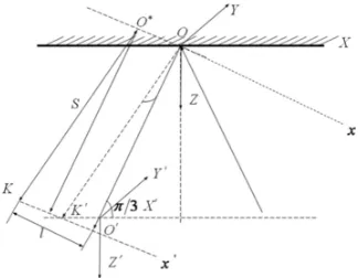
For confirming the misalignment of light spot in horizontal and vertical directions on receiving screen 2 m away, the output should be transformed further, as shown in Fig.10. Where X, Y, and Z are the coordinates of reflector in horizontal and vertical directions operated in ANSYS, coordinates X´OY´ is the coordinates of receiving screen in horizontal and vertical directions, the input coordinates used in calculating the misalignment are x, y, and z, and the input coordinates used in calculating the misalignment are x´, y´, and z´, while z´is the output direction, x´is the vertical output direction, OO´is the output beam without interference and O*K is the output ray under interference. Also our assumption is that l is the projection of output beam on x´axes after transmitting S under interference vibration, h is the offset of light spot on the receiving screen in vertical direction Y´ ,namely, the projection of output beam on y axes after transmitting S under vibration interferer. For instance, it’s assumed that S =2m, then we can obtain that the misalignment
[image:6.612.246.408.395.521.2]in horizontal direction is 18.875 µm, and the misalignment in vertical direction is 185.49 µm.
Figure 10. The geometric relation of misaligned light.
Data and Experimentation Results
In order to prove our design, an experimental optical platform is built. First, a He-Ne laser emitter is got to make a beam, then the beam goes through an attenuation lens and a reflector to 2 m far, at the end, it hits on a CCD(type of the CCD is SONY ICX419ALL)photosensitive plane. Then the reflector is settled on the optical platform with a machine pump, which offers a vibration source, meanwhile, three directions of the reflector base are chosen to dispose the test nodes of vibration sensor.
In the second set of experiments the acceleration of reflector in three coordinates directions are measured by vibration sensor under the vibration power of machine pump, as Fig.4 shows. This vibration power is the outer power signal loaded in transient analysis. Then the light signal is received by CCD, and position of the received light spot can be got by image processing. So the offset of light spot center can be obtained.
At last the misaligned quantity of light spot center in experimentation is obtained, which is
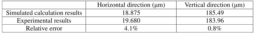
although the vibration provided by the vibration source is mainly in vertical direction, but due to the different material properties of components and the inconsistent vibration state of every parts, the pitching and deflection of the reflector is caused. Thus, the misaligned light reflected by reflector is not just in horizontal direction but also in vertical direction, and the misaligned quantity in vertical direction is much smaller than that in horizontal direction. As shown in Tab.2 the simulated calculation results and experimental results are matched better, and the relative error is 4.1% and 0.8% respectively.
Table 2. The contrast between simulated calculation and experimental results.
Horizontal direction (µm) Vertical direction (µm)
Simulated calculation results 18.875 185.49
Experimental results 19.680 183.96
Relative error 4.1% 0.8%
Conclusions
This paper presents the theory model of luminous transmission in misaligned optical system, completes the dynamics numerical calculation of optical element vibration effect on optical performance, achieves the numerical simulation of light-beam in misaligned optical system under vibration, and proves that the simulation calculation has a higher precision through the vibration experiment. This model has been tentatively used in evaluating the anti-vibration performance of optical system and making optimization design of the mechanical structure of optical system.
Acknowledgments
This work is supported by the State Key Laboratory of Laser Interaction with Matter (SKLLIM) under Grant No. SKLLIM1507.
References
[1] S. Arnon, N. S. Kopeika “The performance limitations of Free Space Optical Communication Satellite network due to vibrations-analog case,” Proceedings of IEEE, 1996, Vo1.84: 287-290.
[2] S. Arnon , N. S. Kopeika “Laser Satellite Communication Network. Vibration Effect and Possible Solutions,” Proceedings of IEEE, 1997, Vo1.85, 1646-1661.
[3] Y. L. Chen, J. Ma, L. Y. Tan, et al. “Analysis of the Effects of Gaussian Beam on Intersatellite Optical Communication,” Chinese Journal of Lasers, 2004, 31(S): 393-395.
[4] L. Y. Tan, J. Ma. “Intersatellite Optical Communication Technology,” Science Press, 2004.
[5] G. M. Chen. “Pointing stability of light-beam in vibration environment and its key techniques of opto-mechatronics,” Xidian University, 2005 (in Chinese)
[6] G. B. Fan. “Light-beam stability and vibration control of opto-mechatronics systems,” Xidian University, 2004. (in Chinese)
[7] G. B. Fan, J. Y. Jia, G. M. Chen, et al. “Vibration effects on pointing precision of optical system,” China mechanical engineering, 2005, 16(2): 104-106, 111. (in Chinese)
[8] L. F. Che, Y. Lu, Z. N. Xu. “Finite element simulation on packaging of hinged high-micromachined accelerometer,” Optics and Precision Engineering, 2007, 15(2): 199-205. (in Chinese)
[11] Y. Wang, J. H. Zhao, J. Y. Du, et al. “Simulation on antishock performance of a marine diesel engine by using finite element calculation based on multibody dynamics,” Journal of Vibration and Shock, 2009, 28(11): 88-90 (in Chinese)
[12] T. Q. Yao, Y. L. Chi, L. H. Wang, Y. Y. Huang. “Contact vibration and flexible-multibody dynamic analysis of a ball bearing,” Journal of Vibration and Shock, 2009, 28(10): 158-162. (in Chinese)
[13] X. L. Ji. “Study on the Propagation Properties and Beam Control of High-power Lasers with Distortions,” Sichuan Normal University, 2004. (in Chinese)
[14] W. Fei, X. F. Chen, X. L. Zeng, et al. “Generation of multi-wavelength light sources for optical communications in aperiodic optical superlattice,” Chinese Optics Letters. 2005, 3(12): 708-711.
[15] X. X. Liang, S. L. Ban. “Optical vibration modes and electron-phonon interaction in ternary mixed crystals of polar semiconductors,” Chinese Physics, 2004, 13(1): 71-81. (in Chinese)