2016 International Conference on Computer, Mechatronics and Electronic Engineering (CMEE 2016) ISBN: 978-1-60595-406-6
Optimal Synthesis of Sum and Difference
Patterns with Arbitrary Sidelobes
Qiong WU, Zheng-dong QI, Xing-Gan ZHANG
*and Ya-duan RUAN
School of Electronic Science and Engineering, Nanjing University, Nanjing, China
*Corresponding author
Keywords: Linear arrays, Sum and difference pattern synthesis, Fast Fourier transform (FFT).
Abstract. A new approach to the power synthesis of fixed-geometry reconfigurable linear arrays radiating sum and difference patterns via uniformly spaced arrays with a number of common excitations is presented and assessed. The proposed technique makes use of the property that an inverse Fourier transform relationship exists between the array factor and the element excitations for a linear array with periodic spacing of the elements. This property is used in an iterative way to derive the array element excitations from the prescribed array factor to manage arbitrary and different bounds concerning radiation performance (field slope, amplitude, or even directivity) of the couple of patterns while sharing part of the feeding network. A set of numerical examples are reported and discussed to support the underlying theory and to show potentialities and features of the arising procedure.
Introduction
Array antennas able to provide both sum and difference patterns, the former having one main lobe along the target direction and the latter exhibiting a null in the same direction, are strongly required in mono-pulse radar systems. As a matter of fact, a very large number of algorithms have been proposed in the last sixty years for the synthesis of such radiating systems [1-9]. The simplification of the hardware complexity has also been addressed by sharing some excitations for the sum and difference channels [1, 2, 8]. More specifically, the grouping of array elements is aimed at generating an optimal sum pattern through independent excitations and a difference pattern by means of the sub-arrayed feed architecture.
Recently, the overall synthesis problem has been carried out by perturbing the roots of the Bayliss distribution to match as much as possible a given Taylor distribution [7, 10]. The weight coefficients of a discrete linear array have been obtained by sampling the continuous aperture distributions. For the planar arrays case, with more advance in convex optimization, the sum and difference patterns is solved through a convex (quadratic) programming procedure. The method allows us to maximize the radiation performance (field slope, amplitude, or even directivity) of both beam patterns.
To illustrate the proposed method, taking advantage of known results in the (separate) optimal synthesis of sum and difference patterns [1], the results presented are related to linear arrays consisting of 10 elements and 20 elements, located in a periodic grid with half wavelength inter-element spacing. They comprise sum and difference patterns.
Sum and Difference Patterns
Let us consider a linear array of 2M elements equally spaced of d along the z-axis and symmetric with respect antenna Centre. Accordingly, the array factor of the sum pattern is given by
sin( )
0
( ) .
M
s j nd
s n
n M n
AF I e
(1)And that of the difference mode is expressed as
sin( )
0
( ) .
M
d j nd
d n
n M n
AF I e
(2)Where Ins and Ind, n =-M,…,-1,1,…, M are sets of excitation weights for the sum and difference
patterns characterized by an even (i.e., Ins=I-ns) and odd (i.e., Ind=-I-nd) distribution, respectively.
Moreover, β=2π/λ, λ stands for the free space wavelength, and θ is the direction angle. The approach is aimed at determining the two sets Ins and Ind, in such a way to provide both a maximization of the
slope of the difference pattern and a sum pattern amplitude greater than a given threshold in the target direction θ0, while subjecting to different and arbitrary upper bounds for the sidelobes of both two
patterns and sharing a number of excitation amplitudes. Accordingly, the synthesis problem can be formulated as the optimization of the following cost function
( ) .
s s s
AF T (3)
1 2
( ) .
d d d d
AF T (4)
( ) ( ), 1, , .
s k s k s
AF UB k K (5)
( ) ( ), 1, , .
d k d k d
AF UB k K (6) and subject to the following constraints on the excitations
, 0.
s d
n n C C
I I n n n (7)
1, , .
s s n n
a a n M (8)
1, , .
d d
n n
a a n M (9)
Wherein In = an, θk (k=1,…,K) is the target direction, Eq. 3 and Eq. 4 indicates the maximization of
field in a target direction corresponding sum and difference pattern. UBs and UBd are non-negative
upper bounds for the sum and difference patterns respectively, defined by a set of K samples taken on the antenna visible range. As shown in [4], the optimal excitations for the two modes are usually very different for the central part of the array and tend to decay away from the center, one will generally look for common amplitudes for |n| exceeding a given threshold nC, which is an integer threshold
Proposed Method
Since Eq. 1 and Eq. 2 represent a finite Fourier series that relates the excitation coefficients of the linear array to its array factor which can be calculated through an inverse fast Fourier transform (IFFT), a direct FFT applied will yield the excitation coefficients. The proposed uses an iterative way to calculate the excitation coefficients adapted to the required sidelobe level, guaranteeing an optimal radiation performance when synthesizing sum and difference patterns with a common aperture. The original MATLAB program presented in [15] requires three modifications.
The first modification concerns the initialization of the phase of all element excitation coefficients. To perform an amplitude-only synthesis, the sum mode means that there exists no phase shift between two halves while a phase shift of π exists between two halves for the difference pattern. After then, a new updated AF will be calculated. The sum pattern is generated by means of the symmetric set of the real optimal Eq. 7, while the difference pattern is defined through an anti-symmetric real excitation set in Eq. 8. The second modification involves in centrosymmetric constraints and the common amplitude excitations. The synthesis for linear sources is carried out by an average operation producing sum and difference patterns with a common tail. Before the average procedure, half of the elements are descriptive of the whole array to ensure the array coefficients are symmetric about the array center. For each iteration, only M samples of K excitation coefficients are retained when truncating user-defined array factor to samples. The coefficients amplitude should be made equal symmetrically to the amplitude of the rest of the Mth element. This process is repeated until the new updated AF satisfies the required sidelobe.
Implementation of the modified iterative Fourier technique algorithm for the synthesis of linear arrays generating optimal sum and difference patterns with a number of common excitation weights is presented as follows:
• Start the synthesis using two sets of array elements for generating a sum pattern through independent excitations and a difference pattern.
• Compute AFs and AFd from Ins and Ind using a K-point inverse FFT, K > 2M.
• Adjust AFs and AFd to the prescribed beam pattern specifications corresponding sum and
difference mode.
• Compute Is and Id for the adapted AFs and AFd using a K-point direct FFT.
• Truncate Is* and Id* from K samples to M samples by making zero in excess of M, |Incommon| =
(|Ins*|+|Ind*|)/2 with n=nc,…,M, the phase excitations of the sum pattern case are set to φns=0,
n=-M,…,M, while the condition of the difference pattern, φnd=0, n=-M,…,-1, φnd=π, n=1,…, M, the
weight coefficients sharing some excitations for sum and difference patterns expressed as:
* * *
1 1 1 1
* 1 1 , , , , , , , , , , , , , . c c c c
s common common common s s s
n M M n n
s common common common
n n M M
I I I I I I I
I I I I
(10)
* * *
1 1 1 1
* 1 1 , , , , , , , , , , , , , . c c c c
d common common common d d d j
n M M n n
d j common j common j common j
n n M M
I I I I I I I e
I e I e I e I e
(11) Repeat the above steps until the radiation performance (field slope, amplitude, directivity) of both beam patterns over assigned directions subject to completely arbitrary masks for sidelobe bounds is reached.
Typically, the initial synthesis using independent excitations for 2M elements has a great influence on the convergence time and convergence results. In first step, symmetric beamforming weights are obtained by Semi-Definite Relaxation (SDR) technique in [16].
Simulation and Assessment
the overall synthesis procedure was less than 0.6s per considered case on a 3.29-GHz PC equipped with 4 GB of RAM). The antennas used are isotropic and the peak directivity of a linear array is given by [1].
2 0 2
0
2 ( ) . ( ) sin
AF D
AF d
(12)
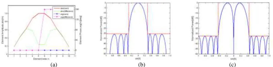
As first test case, the synthesis of a linear array composed of ten elements (λ/2uniformly spaced) with six excitation amplitudes (i.e., the 60% of the overall elementary radiators) shared for the generation of both patterns has been dealt with. Imposing the upper-bound masks shown in Fig. 1(b)-(c), a sum pattern with beam width (BW) equal to 37 (null to null) and sidelobe level (SLL) equal to -30.5dB and a difference power pattern with BW=53.97 and SLL=-32.5dB have been obtained respectively. The two synthesized real sets of excitation coefficients are shown in Fig. 1(a). The sum power pattern has a maximum directivity Dsmax=20.22dB, while the difference power pattern
has a maximum directivity Ddmax =20.22dB.
(a) (b) (c)
Figure 1. (a) Excitation coefficients synthesized for an array composed by N=10 uniformly (λ/2) spaced elements. (b) Sum (power) pattern fed by the currents shown in (a). The dashed curve corresponds to the imposed upper-bound mask. (c)
Difference (power) pattern fed by the currents shown in (a). The dashed curve corresponds to the maximum permitted sidelobe level (SLL).
In the second test case, let us consider a uniform linear array with N=20 elements equally spaced of
d=λ/2 and nChas been set to 5 such that 12 element among 20 (also 60%) are shared between two
patterns. The sum pattern and difference pattern are reported in Fig. 2(b)-(c). The sum power pattern is characterized by SLL=-27.4dB and a -3dB main lobe BW=6.49 [deg]. The difference pattern has SLL=-26.23 dB and BW=5.1 [deg]. The real excitation values synthesized by modified IFT are given in Fig. 2(a). The two set of excitations provide a sum and a difference pattern with maximum directivity values Dsmax =26.2dB and Ddmax =20.36dB.
(a) (b) (c)
Figure 2. (a) Excitation coefficients synthesized for an array composed by N=20 uniformly (λ/2) spaced elements. (b) Sum (power) pattern fed by the currents shown in (a). The dashed curve corresponds to the imposed upper-bound mask. (c) Difference (power) pattern fed by the currents shown in (a). The dashed curve corresponds to the maximum permitted side
lobe level (SLL).
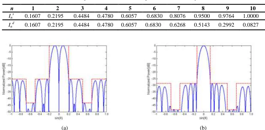
[image:4.595.74.529.295.407.2] [image:4.595.77.507.570.680.2]modality in the angular depression region. The pattern features of some representative results are listed in Table 1 (wherein only half values are included by virtue of symmetrical behavior) which fully ensures the generality and flexibility of the proposed technique.
Table 1. Weight Coefficients for Sharing 60% Excitation Amplitudes.
n 1 2 3 4 5 6 7 8 9 10
Ins 0.1607 0.2195 0.4484 0.4780 0.6057 0.6830 0.8076 0.9500 0.9764 1.0000
Ind 0.1607 0.2195 0.4484 0.4780 0.6057 0.6830 0.6268 0.5143 0.2992 0.0827
(a) (b)
Figure 3. (a) Difference power pattern corresponding to the excitations of Table I. The dashed curve corresponds to the imposed upper-bound mask, and has provided the presence of two depressions in the directions located at ±37。 from boresight. (b) Sum power pattern corresponding to the excitations of Table I. As in Fig.7, the upper-bound mask has two
depressions 20 dB lower than the peak sidelobe level (PSL).
Summary
In this letter, an innovative strategy for the synthesis of linear arrays with common excitations generating optimal sum and difference patterns has been presented and assessed. The array excitations providing an optimal sum beam for given performances on the difference beam have been determined in a globally optimal fashion by means of a modified inverse fast Fourier technique. The approach allows one to maximize the radiation performance for each pattern. Numerical results have shown the effectiveness and reliability of the proposed.
References
[1] B. Fuchs, A. Skrivervik, and J.R. Mosig, Shaped beam synthesis of arrays via sequential convex optimizations, IEEE Antennas and Wireless Propagation Letters, vol. 12, pp. 1049-1052, 2013.
[2]P. Rocca, A.F. Morabito, and T. Isernia, Synthesis of arbitrary sidelobes sum and difference patterns with common excitation weights, In 2010 IEEE Antennas and Propagation Society International Symposium, pp. 1-4, 2010.
[3] M. Li, X. Wang, and J. Dong, Optimal difference pattern synthesis with polarization control for arbitrary arrays, IEEE Antennas and Wireless Propagation Letters, vol. 11, pp. 1358-1361, 2012.
[4] P. Rocca, A.F. Morabito, Optimal synthesis of reconfigurable planar arrays with simplified architectures for monopulse radar applications, IEEE Transactions on Antennas and Propagation, vol. 63(3), pp. 1048-1058, 2015.
[6] O. M. Bucci, M. D'Urso, T. Isernia, Optimal synthesis of difference patterns subject to arbitrary sidelobe bounds by using arbitrary array antennas, IEE Proceedings-Microwaves, Antennas and Propagation, vol. 152(3), pp. 129-137, 2005.
[7] M. Alvarez-Folgueiras, J. A. Rodriguez-Gonzalez, F. Ares-Pena, Synthesising Taylor and Bayliss linear distributions with common aperture tail, Electronics Letters, vol. 45(1), pp. 18-19, 2009.
[8] T. S. Lee, T. K. Tseng, Subarray-synthesized low-side-lobe sum and difference patterns with partial common weights, IEEE transactions on antennas and propagation, vol. 41(6), pp. 791-800, 1993.
[9] L. Manica, P. Rocca, A. Martini, An innovative approach based on a tree-searching algorithm for the optimal matching of independently optimum sum and difference excitations, IEEE Transactions on Antennas and Propagation, vol. 56(1), pp. 58-66, 2008.
[10] T. Taylor, Design of circular apertures for narrow beamwidth and low sidelobes, IRE Transactions on Antennas and Propagation, vol. 8(1), pp. 17-22, 1960.
[11] W. Keizer, Element failure correction for a large monopulse phased array antenna with active amplitude weighting, IEEE Transactions on Antennas and Propagation, vol. 55(8), pp. 2211, 2007.
[12] W. P. M. N. Keizer, Fast low-sidelobe synthesis for large planar array antennas utilizing successive fast Fourier transforms of the array factor, IEEE Transactions on Antennas and Propagation, vol. 55(3), pp. 715-722, 2007.
[13] W. P. M. N. Keizer, Linear array thinning using iterative FFT techniques, IEEE Transactions on Antennas and Propagation, vol. 56(8), pp. 2757-2760, 2008.
[14] W. P. M. N. Keizer, Large planar array thinning using iterative FFT techniques, IEEE Transactions on Antennas and Propagation, vol. 57(10), pp. 3359-3362, 2009.
[15] W. P. M. N. Keizer, Low-sidelobe pattern synthesis using iterative Fourier techniques coded in MATLAB, IEEE Antennas and Propagation Magazine, vol. 51(2), pp. 137-150, 2009.