2017 2nd International Conference on Communications, Information Management and Network Security (CIMNS 2017) ISBN: 978-1-60595-498-1
Research of Interactive Fault Reasoning Based
on Process Data Module in IETM
Li-rong MENG, Yong-qi MA
*,
Xing-lin ZHU and Jia-ju WU
Institute of Computer Application China Academy of Engineering Physics, Mianyang, China
*Corresponding author
Keywords: Fault isolation, Fault reasoning, Interactive, Progress data module, IETM.
Abstract. Fault isolation and fault maintenance support is an important function, and how to improve
the fault isolation mission success rate is an unavoidable problem for IETM using in integrated logistic support informatization. Aim to solve the low interactive, location inaccurate, one-sided guidance problems in fault isolation and fault maintenance, this paper use process data module to describe full process for fault diagnose, fault isolation and fault maintenance, and then according to interactive fault reasoning principle based on process data module to guide fault maintenance man accomplish fault reasoning, isolation and maintenance in shorter time. As a result, this improves the accuracy and efficiency of fault remedy and maintenance, also upgrade the efficiency of integrated logistic support.
Introduction
Interactive Electronic Technical Manual (IETM) refers to the integrated application of computer multimedia, database and network technology advantages, organizing the operation manual, maintenance manual and other information in accordance with relevant standards, and will be in the form of optimal text, tables, graphics, engineering graphics, sound, video, animation, and other information displayed on the electronic screen, consulting interactively, and will accurately show the information that maintenance technicians or system operator need to speed up the implementation of the equipment use and support activities. As one of the ten elements of equipment integrated support, the widespread use of IETM is important to reduce the cost of equipment support, improve the efficiency of equipment integrated support is of great importance. At the same time, it has a significant advantage of shortening the time of failure maintenance and improving working efficiency, which has become a hot spot in the research of information technology.
In all functions of IETM, an important function in the process of fault isolation and maintenance is to provide isolation and maintenance support, guide the breakdown maintenance personnel in a relatively short time for fault isolation, reasoning and maintenance, so as to improve the accuracy of troubleshooting and maintenance, efficiency, maximize the efficiency of equipment integrated support. And the realization of IETM interactive process data module type fault isolation and maintenance process of interaction, the basis of how module based on process data play a role of IETM fault isolation and maintenance is the main content of this article research.
Progress Data Module
Function of Process Data Module
program with multiple interactive functions, consisting of multiple data modules or steps in a special order.
The purpose of the data process module design is to realize the interaction process of IETM, acquisition, storage, and operation status information ability. It can fully describe a complete fault diagnosis, isolation and maintenance process. The interaction functions that process data modules can achieve are mainly [3,4] as following:
1) Fault diagnosis, especially dynamic diagnosis and system simulation.
2) Implement external procedures to achieve IETM interaction with external programs. 3) Interactive functions such as navigation, tracking and dialog driving.
4) Information filtering, which presents the information needed to match the current situation of the user.
5) Order traversal, especially for test and platoon, the next step is to decide based on current dynamic state information or external input.
Structure of Process Data Module
[image:2.595.98.495.350.631.2]The process data module uses the element <process> tag. The content organization takes the node as the basic element. And the execution sequence of the data module can be constructed using sequence, branch, condition, and loop 4 node types. According to the S1000D standard, the pattern structure of the entire process data module is shown in figure 1.
Figure 1. Process data module structure model. [3]
It contains the following child elements in the main elements < the process > : variable declaration < variableDeclarations >, commonl information < commonInfo >, preliminary requirements < preliminaryRqmts >, data module sequence < dmSeq > and close requirements < closeRqmts >. Two of the important sub-elements are the < variableDeclarations> and <dmSeq >, the former is used to declare variables and initial values, while the latter is the elements of aggregation sequence information.
dialog box or dialog box branch, variable initialization and three other sub elements. The dialog < dialog > element provides 5 kinds of interaction, such as the blanks, menus, buttons, message boxes, and dialog boxes to receive the user's input and assign the variables, so as to realize information interaction between user and logic engine.
< dmSeq > element is the main content of the data process module which determines the steps, dialogue, external application request, and the order of conditions in the data module. At the same time, it defines the logical order of sub elements < dmNode >, < dmNode >, < dmIf > and < dmLoop >.
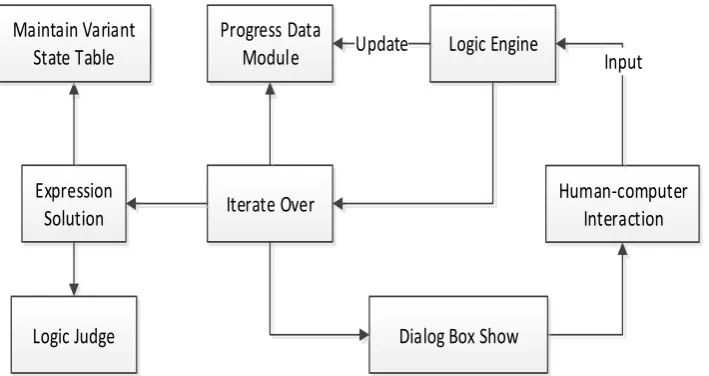
In the IETM platform, the interactive logic structure is described by the process data module, and the implementation of interactive functions requires the logic engine to complete. Logic engine is the software part that performs the data module process. It is the interpreter of program script six, which is completed by the Schema based on the process data module. For example, the element < dmSeq > is processed, and the contents are sorted by the result of processing. For example, the element < dmSeq > is processed, and the contents are sorted by the result of processing. The function of logic engine in the interaction and fault diagnosis of IETM is mainly embodied in the following 4 aspects: the traversal process data module maintains the variable status table, evaluates the expression, and the dialog box appears, as shown in Figure 2.
Progress Data Module
Iterate Over
Logic Engine Update
Expression Solution
Human-computer Interaction
Logic Judge Maintain Variant
State Table
Dialog Box Show
[image:3.595.123.478.325.513.2]Input
Figure 2. Logical engine functional structure.
Logic engine gets the input from the human-computer interaction interface, traverse the data process module, evaluates the expressions of the obtained variables. At the same time, make the dialog box rendering, the resulting calculations are used for logical judgment and maintenance of variable expressions. If the output result of logical judgment is not a clear equipment failure, the next test task will continue according to human-computer interaction.
Interactive Fault Isolation
The interactive fault reasoning based on IETM needs to be combined with the feature of fault, the test results and user experience to conduct a comprehensive systematic analysis of internal flow through process data module to guide or according to customer's instruction to get test jump conditions, gradually to reasoning, detection, location and isolate fault thoroughly.
fault information fault appearance test result fault feature fault signal expression solution variable assignment IETM’s human-computer interaction interface (query、display)
progress data module of fault reasoning
test task Pre require ment test result expres sion diagnose rule postrequ irement user feedback and evaluate IETM learning/fault information update/knowledge repository update
logic engine(reasoning algorithm)
domain expert remote support solution has locate fault or not no clearing of fault or not
yes no yes maintenance plan precondition Test unit Troublesh ooting unit rule and case
[image:4.595.140.453.69.315.2]match match output fault reasoning diagram fault reasoning diagram
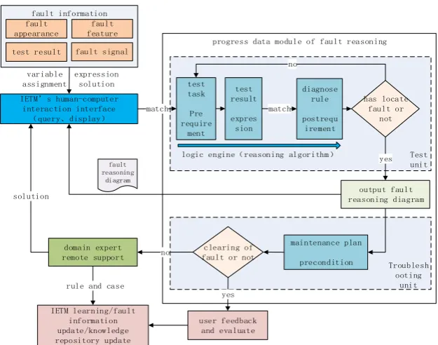
Figure 3. Interactive fault reasoning model.
The fault reasoning process data module contains the precondition, link unit, test unit and the troubleshooting unit. The precondition gives the expression of variables that must be satisfied in the fault reasoning process data module. The test unit is a description of the inspection task and the status of the test results, which is used to match the diagnostic reasoning rules to locate the fault. The link unit provides information about fault isolation, maintenance related text, images, multimedia, etc.
In interactive IETM fault reasoning is the process of the user in an interactive interface through the dialog input fault phenomenon, inside the IETM system to carry on the corresponding variable assignment, so IETM system can get a fault state variable expression, the expression with fault reasoning process data module in the system the preconditions for expression of matching, to activate the corresponding fault reasoning process according to the results of the operation data module, again the fault reasoning process according to activate data module, the logical process of reasoning according to the test results and the operation result to decide whether to have positioning fault diagnosis rules or the next test task is needed. All diagnostic rules include an end request containing an assignment statement, which requires that the test continue to be tested when there is no location failure, and end the test after the location failure and enter the platoon unit.
After the troubleshooting unit, the troubleshooting can't be ruled out, so the remote support of the domain expert can help the troubleshooting. Domain experts, according to the fault information, propose a solution to guide the troubleshooting staff to fault reasoning interactively by IETM.
After troubleshooting unit successfully troubleshooting, users can feedback in the IETM platform interactive diagnosis reasoning process, at the same time if the IETM platform integrates fault knowledge base, knowledge base maintenance and tool instrument libraries, depending on the fault reasoning, update the corresponding knowledge base maintenance process, and the rules of the domain experts to form unified analysis case can also be stored into the knowledge base management, the updated knowledge base for the next fault reasoning constantly optimize the logical process of reasoning, thereby improving the success rate of fault reasoning.
An Instance of Progress Data Module
cause of the fault has been found and the fault isolation flow diagram can be output. After finding the cause of fault, the process data module will call the troubleshooting unit and guide the user to carry out the maintenance, thus complete the whole process of failure reasoning and maintenance.
Summary
With the continuous application of IETM in the equipment integrated logistic support, especially the use of process data module, the interactivity and accuracy of fault reasoning and maintenance are greatly improved. At the same time, as the reasoning mechanism based on process data module does not need frequent access to the database in the actual reasoning process, so it has a good independence to make the reasoning process relatively concise and clear. However, because the implement of interactive fault reasoning need logic engine, so the logic engine’s processing efficiency and accuracy play a decisive role for interactive fault reasoning. Then the logic engine processing efficiency and accuracy are worth for further research.
References
[1] Zhu Xingdong, Weaponry Interactive Electronic Technical Manual: IETM. Defense Industry Press; 1 (December 1. 2009).
[2] Xu Zongchang, IETM equipment interoperability and interactivity. Defense Industry Press (Sept. 22 2014).
[3] ASD/AIA S1000D, International Specification For Technical Publications Utilizing A Common Source Database(4.0). 2008,8.
[4] GJB6600, Equip interactive electronic technical manual. 2008.
[5] Wu Yongming, Ye Haisheng, “Research on Technology of Materiel Fault Diagnosis System Based on IETM”. Computer Measurement & Control. 2011.19(10).
[6] Wang Fei, “Electron spectroscopy studies on magneto-optical media and plastic substrate interface,” Informatization Research. Vol.42 No.3 Jun.2016.
[7] Zhou Qijun, Zhao Qiuying, Zhu Mingming, “TT & C System Fault Diagnosis Method Based on Fault Tree”. Modern Electronics Technique, 2015 (7): 103-106.
[8] Ge Yuefei, Wang Rong, Chen Shiwen, Zhang Lin, “Research and realization of Automatic Fault Tree Synthesis Technology”. Computer Engineering and Design, 2009, 30 (1) 207.
[9] Zhao Z. UML Model to Fault Tree Model Transformation for Dependability Analysis. Carleton University Ottawa. 2014.
![Figure 1. Process data module structure model. [3]](https://thumb-us.123doks.com/thumbv2/123dok_us/283793.1029056/2.595.98.495.350.631/figure-process-data-module-structure-model.webp)