2017 2nd International Conference on Computer, Mechatronics and Electronic Engineering (CMEE 2017) ISBN: 978-1-60595-532-2
Research on the Sliding Mode Control in Cam Grinding
Xiu-mei CHEN, Bao-ying PENG, Qi-guang LI and Huai-jian XIA
Beijing Information Science & Technology University, Beijing, 100192, China
Keywords: Sliding mode variable structure, Servo system, Quasi-sliding mode, Dynamic switching function.
Abstract. It is difficult to obtain the cam profile accurately in cam grinding because of the complicated contour, the grinding force fluctuate, the tracking performance of the servo system and other interferential factors. The tracking performance of the servo system has a great influence on the cam profile error and leads to the reduction of the cam profile precision. In order to reduce the profile error of cam and improve the machining accuracy, the tracking performance of each servo axis is improved by using sliding mode variable structure control method. The sliding mode variable structure controller adopting the method of proportional switching, quasi-sliding mode and dynamic switching function are designed respectively. The simulation analysis are carried out, and the results of simulation show that the tracking error can be reduced effectively using the sliding mode variable structure control in cam.
Introduction
The contour of cam is created by X-C linkage motions. As the cam profile is non-circular shape, the grinding point velocity and acceleration will mutate constantly. It leads to the servo system tracking lag occur which has a great influence on cam machining precision. Therefore, it is necessary to obtain better tracking performance of each servo system for improving the cam accuracy. In order to eliminate or reduce axis tracking position error, scholars at home and abroad have conducted a lot of research on the tracking control method of servo axis. Masayoshi Tomizuka presented the Zero-phase error tracking control algorithm (ZPETC [1]). R. Ramesh etc. researched the error of NC servo system and the profile error [2]. Hace A. designed the open CNC controller, and the adaptive function control was applied to the controller design [3]. Wang D etc. applied the adaptive dynamic control method in the servo axis position tracking control in high speed machine [4]. In addition, many scholars had studied the compensation to external disturbances in servo system. Kim designed a fuzzy disturbance observer for feedback tracking control when it adopted multiple input multiple output system output, and the observer was applied to control the speed of the synchronous motor [5]. Lu YS had studied the sliding mode control of the perturbation observer [6]. All above researches on servo system tracking performance improved the position tracking accuracy in different degree. But the cam profile is non-circular, the material of grinding removal is constantly changing and the grinding force changes constantly. The variation of the grinding force is reflected to each servo axis and leads to the speed change. Then, the cam profile error generate on account of the position deviation of servo system which is caused by its speed change.
The Model of X Axis in Cam Grinding Machine
The Model of X-axis
The position of grinding wheel is mainly controlled by the X-axis servo system. Fig.1 shows the scheme of its structure.
The linear motor drives the grinding wheel shelf to realize the straight-line reciprocating motion of X axis in figure 1. Fig. 2 shows the block diagram of X axis system. Considering the mass of the parts in the servo system, the X axis location model of cam can be obtained:
) (
) ( ) (
974 20546 1
+ = × =
s s s s G s
G v
Where: u-the input signal, y-the output signal, Gv(s)-the speed transfer function of X axis,
Gc(s) –the transfer function of controller.
Figure 2. The block diagram of X axis system.
The Model of C-axis
The C axis mainly drives the workpiece to rotate. The rotation of the workpiece was driven by the control of the NC instructions, the input signal is angle position, and the output is angle displacement of the part. Fig.3 shows the scheme of C axis system.
Figure 3. The scheme of C axis.
Fig. 4 shows the block diagram of C axis system .The C axis location model of cam is:
) 680 (
9000 1
) ( ) (
+ = × =
s s s s G s
G v
Where: θd-the input signal, θ-the output signal, Gv(s)-the speed transfer function of C axis, Gc(s)
–the transfer function of controller.
Figure 4. The block diagram of C axis system.
Three Kinds of Sliding Mode Control Methods in Cam Grinding
(1) The sliding mode variable structure control based on proportional switching. If the second order system position state equation is:
Df Bu Ax x= + +
The control switch function of the sliding mode variable structure is:
e ce s= + ′
The control strategy generally follows the sliding mode existence condition:
0 lim
0 <
→ dt
ds s
s
And the Control law is: u(t)=(αe +βe)(εsgn(s)+ks)
According to the condition of sliding mode control stability, the liapunov function is constructed:
=
V ( () u(t) n(t))
dt dx t
u e c s s
s×= × 1+ +974× +20546× −
0
≤ ⋅ + − + − + −
× + =
×s (ce e) ( εsgn((ce e)) K(ce e)) (ce e) n(t)
=
V ( ) ( () 680 9000 u(t) n(t))
dt dx t u e c e ce s
s×= + × + + × + × −
0 ) ( ) ( )) ( )) sgn(( ( ) ( + × − + − + − + ⋅ ≤ =
×s ce e ce e K ce e ce e nt
s ε
The stability condition is satisfied in C axis system.
Fig. 5 shows the sliding mode variable structure controller model based on proportional switching.
Figure 5. The sliding mode variable structure controller model based on proportional switching.
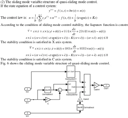
(2) The sliding mode variable structure of quasi-sliding mode control. If the state equation of a control system:
) ( ) ( ) , ( ) ( t n t bu t x f
y n = + +
The control law is: ( () ( ) ( , )) (εsgn(s) Ks)
b t x f u e c b u n i n i
i + − + +
=
∑
− = 1 1 1 1According to the condition of sliding mode control stability, the liapunov function is constructed:
=
V ( () u(t) n(t))
dt dx t u e c s s
s×= × 1+ +974× +20546× −
0 ) ( ) ( )) ( )) sgn(( ( ) ( + × − + − + − + ⋅ ≤ =
×s ce e ce e K ce e ce e nt
s ε
The stability condition is satisfied in X axis system.
=
V ( () u(t) n(t))
dt dx t u e c s s
s×= × 1+ +680× +9000× −
0 ) ( ) ( )) ( )) sgn(( ( ) ( + × − + − + − + ⋅ ≤ =
×s ce e ce e K ce e ce e nt
s ε
The stability condition is satisfied in C axis system.
[image:3.612.146.462.151.267.2]Fig. 6 shows the sliding mode variable structure of quasi-sliding mode control.
Figure 6. The sliding mode variable structure of quasi-sliding mode control.
[image:3.612.88.505.288.671.2] = + + = − = = + 1
1 12 1
x y η u x g x f x n i x x n i i ) ( ) ( ,... ,
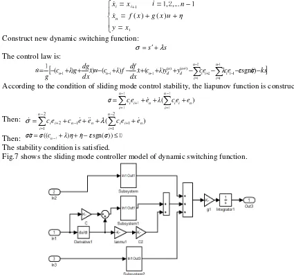
Construct new dynamic switching function:
s s λ σ = ′+ The control law is:
[
x c λy y ce λce ε σ ks]
dx df f λ c u x dx dg g λ c g u n i i i i n i i n d n d n n
n + + − + − + + + − − − −
− =
∑
∑
− = − + − = + − −− ) ) ( ) ( ) sgn()
( () ( ) 1 1 1 2 2 1 1 1 1 1 1
According to the condition of sliding mode control stability, the liapunov function is constructed:
) ( n n i i i n i n i
ie e λ ce e
c
σ=
∑
+ +∑
+− = + − = 1 1 1 1 1
Then: ( 2 )
1 1 1 2 2 1 n n i i i n n i n i
ie c e e ce e
c =
∑
+ + +∑
+ − = + − + − = λ σThen: σσ=σ((cn−1+λ)η+η−εsgn(σ))≤0
The stability condition is satisfied.
[image:4.612.87.512.69.467.2]Fig.7 shows the sliding mode controller model of dynamic switching function.
Figure 7. The sliding mode controller model of dynamic switching function.
The Comparison and Analysis of Simulation Data
[image:4.612.156.455.306.469.2] [image:4.612.190.425.595.727.2]Figure 9. The C axis tracking position error using different sliding mode controller.
Figure 10. X-C linkage tracking position error using different sliding mode controller.
The conclusions can be drawn by comparing the error among the different controller.
(1) In the three different control methods, the error fluctuation of X axis using the sliding mode control of dynamic switching function is the smallest, the next one is the error using quasi-sliding mode control method. The controller error based on proportional switching is the largest in the three control methods. The simulation results show that: in the three kinds of sliding mode variable structure control method, the shaking vibration of the servo axis using the proportion switching function control method and the quasi-sliding mode control method is relatively serious, and their tracking position error is larger than the error using the dynamic sliding mode control switching function method. In conclusion, the dynamic sliding mode control switching function method is best in the three different control methods.
(2) In the three different control methods, the error fluctuation of C axis using the quasi-sliding mode control method is smallest. The next one is the error fluctuation of dynamic switching function method. The error fluctuation based on proportional switching is the largest in the three control methods. The simulation results show that: in the three kinds of sliding mode variable structure control methods, the shaking vibration using the proportion switching function method and the dynamic sliding mode control method is relatively serious, the shaking vibration of C axis using quasi-sliding mode control method is best in the three different control methods in cam grinding.
[image:5.612.158.453.262.415.2](4) The simulation results show that the tracking performance of each servo axis can be ensured using the sliding mode variable structure control method and the accuracy of cam profile can be improved.
Conclusion
According to the principle of cam grinding, the model of X axis and C axis system are built in cam grinding machine. This paper presents that the accuracy of the cam profile can be improved by using the sliding mode control method. The conclusion can be drawn that the tracking precision is better with the Matlab/Simulink software analysis by using the three different sliding mode control methods. At the same time, the application of the sliding mode control in cam grinding provide some theoretical basis for the control of servo system in cam gringing.
Acknowledgements
This research was financially supported by The National Natural Science Foundation Project of China ((Grant No. 51375056 and 51405026), the Beijing Municipal Education Commission Project (Grant No. KM201711232001), and the Beijing Municipal Science and Technology Project (Grant No. Z161100001516002)
Reference
[1] Masayoshi Tomizuka. Zero Phase Error Tracking Algorithm for Digital Control [J]. Journal of Dynamic Systems, Measurement, and Control, 1987, Vol. 109: 65-68.
[2] R. Ramesh, M. A. Mannan, A. N. Poo. Tracking and contour error control in CNC servo systems [J]. International Journal of Machine Tools & Manufacture, 2005, Vol.45:301-326.
[3] Hace A, Jezernik. The open CNC controller for a cutting machine[C]. Proceedings of the IEEEInternational Conference on Industrial Technology, 2003, 2:1231-1236.
[4] Wang D, Li C. Self-adaptive dynamic matrix control for high-speed machining servo control [J]. The International Journal of Advanced Manufacturing Technology, 2003, 21 (10-11): 733-738.
[5] Kim, Euntai. Output feedback tracking control of MIMO systems using a fuzzy disturbanceobserver and its application to the speed control of a MP synchronous motor[C]. IEEE Transactionson Fuzzy Systems, 2005, 13 (6): 725-741.