University of Huddersfield Repository
Myers, Alan, Barrans, Simon, Longstaff, Andrew P., Fletcher, Simon and Ford, Derek G.
Evaluation and Comparison of a Large Machine Tool Structure with ISO Standard Alignment Tests
Original Citation
Myers, Alan, Barrans, Simon, Longstaff, Andrew P., Fletcher, Simon and Ford, Derek G. (2009)
Evaluation and Comparison of a Large Machine Tool Structure with ISO Standard Alignment Tests.
In: Laser Metrology and Machine Performance. Euspen Ltd, euspen headquarters, University of
Cranfield, pp. 5766. ISBN 9780955308277
This version is available at http://eprints.hud.ac.uk/id/eprint/5565/
The University Repository is a digital collection of the research output of the
University, available on Open Access. Copyright and Moral Rights for the items
on this site are retained by the individual author and/or other copyright owners.
Users may access full items free of charge; copies of full text items generally
can be reproduced, displayed or performed and given to third parties in any
format or medium for personal research or study, educational or notforprofit
purposes without prior permission or charge, provided:
•
The authors, title and full bibliographic details is credited in any copy;
•
A hyperlink and/or URL is included for the original metadata page; and
•
The content is not changed in any way.
For more information, including our policy and submission procedure, please
contact the Repository Team at: [email protected].
Evaluation and comparison of a large machine
tool structure with ISO standard alignment
tests
A. Myers, S M Barrans, A P Longstaff, S Fletcher, D G Ford
Centre for Precision Technologies, University of Huddersfield, England
Abstract
In order to satisfactorily machine precision components it is necessary for machine tools to be able to achieve extremely high levels of geometric accuracy. This requires their structures to be extremely rigid such that deflections caused by self weight and traversing of the moving elements do not induce distortions that exceed the required tolerances of the components which are manufactured by the machines.
To aid this aspect of machine tool technology, a range of standards have been systematically created which specify in great detail a variety of geometric tests which can be applied to the various configurations of machine tools currently in use today. Certain machine tool companies will use national or ISO standards, others will create their own, often based upon the ISO but tailored to suit their specific machine configuration and characteristics.
However, achieving the required tolerances can be extremely difficult due to a number of reasons such as geometric errors, thermal distortions causing errors to change as temperatures change and load errors causing the errors to change due to the variation in load magnitude and the changes in positions of the loads. One major source of load errors on large machine is caused by the machine’s own weight and its re-distribution as the machine is traversed through its own working stroke, whereas another significant source is caused by the variety in component weights and their variation in position, either on static or moving table machines. In some cases the tolerances specified in standard tests can be tighter than grade “A” straightedge tolerances and achieving this accuracy under conditions which apply to large and heavy machine tool installations can cause significant problems and considerable unanticipated costs.
1 Introduction
This paper investigates the effect of the static machine self weight and component load errors on a typical machine tool structure, including the concrete foundation and how the magnitude of these errors compare with the allowable tolerances as specified by typical official standards.
The paper discusses how the discrepancies between actual machine errors and the standard tolerances specified can be minimised and overcome on a typical machine tool configuration, by appropriate use of Finite Element Modelling at the design stage, sufficiently robust specification of foundation stiffness and improved measurement techniques.
2
Machine configurations and associated standards
Machines which are being addressed by this paper can typically have traverse dimensions of 20m for the “X” axis, 5m for “Y” axis and 1.5m for the “Z” axis.
2.1 Machine configurations and components
Two examples of types of machine tools are being considered in this paper, travelling gantries and moving column machines, both of which are prevalent in most large manufacturing facilities and are used to produce a vast range of components found in the general engineering industry, in particular in the rail, automotive, ship building and aerospace sectors.
Typical component examples are aircraft parts such as turbine engine casings, wing spars, stringers, ribs and skins, undercarriage parts, fuselage frames and skins or the engine bed plate for a nuclear submarine.
[image:3.595.210.401.442.589.2]Figure 1 shows the machining of a general engineering fabrication and in Figure 2 the crankcase for a large marine diesel engine can be seen with the half cap bearing housings for the crankshaft being bored and faced.
[image:3.595.92.290.443.591.2]A specific requirement is that these machines are constructed to tolerances which are very precise and in practice can be very difficult to achieve, particularly in normal factory conditions without air conditioning and which are susceptible to significant fluctuations of the environmental temperature.
To assist determination of the required tolerances there is now an increasingly large number of national and international standards available for the many different configurations of machine that recommend the tolerances to which the individual characteristics of the machine should be produce e.g. straightness of the “X” axis should be no greater than 5 microns per metre of traverse.
2.2 Associated ISO standards
[image:4.595.89.402.336.504.2]The International Standards Organisation (ISO) corresponding alignment test standards for the specific configurations of machines shown in figure 3 and figure 4 are ISO 8636-2:2007 [1] and ISO 3070-2:2007 [2] respectively. The standards specify a wide range of tests (in excess of 20), some of which are influenced by the moving of the machines through their traverses or the placing of components on the work support areas (work-plates). It is these tests that are being considered in this paper. A more general standard, ISO 230-1:1996 [3] covers the generic method of testing for all machine tools.
Figure 3: Moving gantry type mc Figure 4: Moving column type mc
3
Critical alignment tests
3.1 Gantry type machine tests
3.2 Column type machine tests
The “X” axis straightness measured in the vertical plane is influenced by traversing of the moving column and the component weight and its position. The “Y” axis verticality measured in the horizontal plane is influenced by traversing of the column, the head-slide, the ram and the component weight and position.
The “Y” and “Z” axes alignments are both influenced by traversing of the head-slide and the ram.
3.3 Tolerance values
Typical value for straightness tolerance is circa 10 micron per metre for each axis. These types of machine are generally installed to a gravitational reference initially though this is not a requirement of the standards since it is not necessary to ensure the component is machined correctly. It is done to establish a datum for subsequent reference to check whether or not subsidence might have subsequently occurred due to the foundation or the sub-soil beneath it.
3.4 Equipment used for measurement
A wide range of equipment is used for checking the large machines, such as water levels, electronic levels, taut wire and microscope, alignment telescopes, laser trackers, laser interferometers, dial test indicators, straightedges and squares.
4
Finite Element Modelling (FEM)
By use of Fininte Element Analysis it is possible to determine within a high confidence level whether or not traversing of the machine and or the weight and position of the workpiece will adversely affect the alignments mentioned in “3.1” and “3.2” to such an extent that the machine cannot be constructed within the allowable tolerances mentioned in “3.3”.
4.1 Assumptions
By careful consideration of all relevant characteristics of the machine structure, including the foundation and sub-soil etc and assuming linear behaviour of all elments it is possible to accurately predict the static stiffness of all significant structural members.
From this information it can be determined whether or not deflections will take place such that the tolerances specified in the corresponding standard test sheets can be met.
4.3 Data required for FEM
To carry out succesful FEM structural information is needed on all major elements of the machine through from the sub-soil, concrete foundation, foundation connectors, grout material, casting material, guide-way linear bearing stiffness values, journal bearings stiffness for the main spindle etc. However, this analyis is stiffness based and unlike stress analysis, in this case, certain details such as fillets and bolt holes etc can be ignored since they have a second order effect on the resulting deflections and distortions.
To achieve sufficient accuracy with the FEA it is not only necessary to have the manufacturing drawings of all major structural members in order to provide dimensional information as well as Young’s Modulus etc but also such data as the Coefficient of Uniform Elastic Compression for the sub-soil and the “E” value for the concrete appropriate for the level of steel re-enforcement.
4.4 Finite Element Model of machine and component
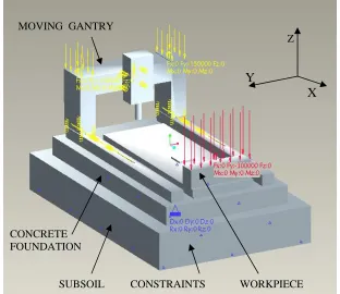
A full model of a typical gantry machine, see figure 5, based upon work carried out [4] [5] [6], has been developed using Pro/e 3D CAD [7],to specifically analyse static distortions.
MOVING GANTRY
Z
Y
X
CONCRETE FOUNDATION
[image:6.595.91.403.320.590.2]
SUBSOIL CONSTRAINTS WORKPIECE
Relevant dimensional detail taken from manufacturing drawings was used to construct the model which included all major structural members, sub-soil, concrete foundation, foundation connectors, beds, guide-way linear bearings, gantry beam, headstock, ram and spindle.
4.5 Finite Element Analysis of machine
Using Pro/e Mechanica [7] the model was analysed to evalutate the distortions and deflections which would occur due to the machine traversing through its full “X” axis travel and the loading of various simulated components onto a range of positions on the work-plates.
5 FEA
Results
5.1 Deflections due to machine moving weight
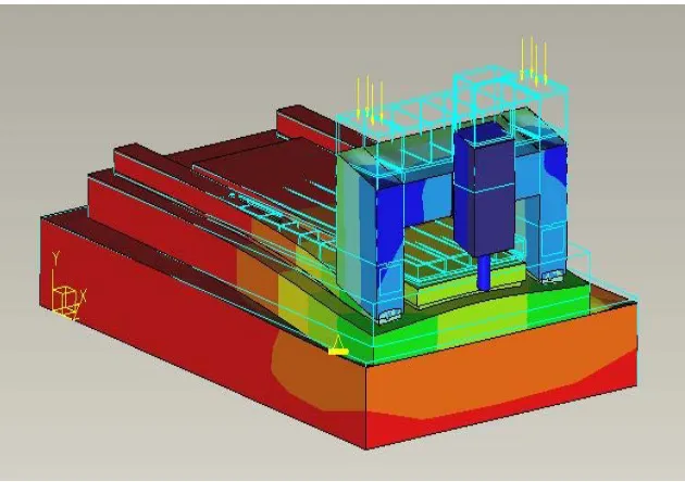
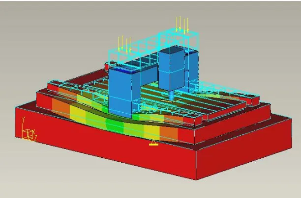
Movement of the gantry (35 Tonnes) along the “X” axis was simulated and the deflected shape of the machine beds were computed to show the error in straightness that would result from the machine overall structural compliance, as shown in figures 6 and 7 below.
The machine gantry was moved in a number of discrete increments and the bed shape determined for each position. From this a resulting profile for the machine straightness of movment in the vertical planeent could be determined.
[image:7.595.86.401.365.587.2]
Figure 7: Deflection of the machine beds with gantry at mid X traverse
5.2 Deflections due to work-piece weight at various positions
5.2.1 Work-piece at minimum X traverse position
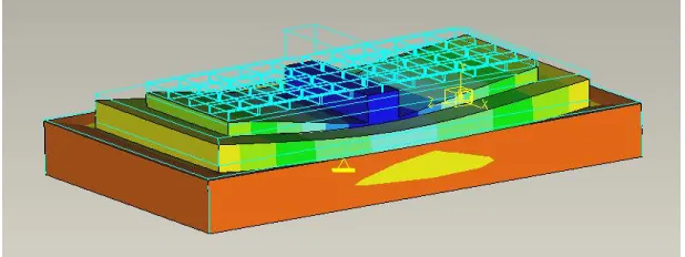
Figures 8, 9 and 10 show the workplate, foundation and subsoil distortion resulting from the heaviest component, equal to a uniformly distributed load of 30 Tonne over a 4m by 1m area of the workplate.
Figure 8: Deflection of the workplates due to workpiece at X minimum
5.2.2 Work-piece at quarter X traverse position
Figure 9: Deflection of workplates due to workpiece at quarter X axis
[image:9.595.93.402.293.409.2]5.2.3 Work-piece at middle of X traverse position
Figure 10: Deflection of workplates due to workpiece at quarter X axis
5.3 Comparison of tolerances
The most critical tolerances are for “X” axis straightness and pitch were compared with measured and predicted values for moving gantry and workpiece loadings as shown in tables 1 and 2.
Table1: Comparision of ISO, FEA and measured values
MOVING GANTRY MACHINE
ISO tests FEA Measured
Test No. Test type
Tolerance (microns / metre)
G2a Pitch 100 140 130
Table2: Comparision of ISO, FEA and measured values
MOVING COLUMN MACHINE
ISO tests Measured
Test No. Type
Tolerance
G3a Straightness 50 microns 70 microns G4a Pitch 60 microns / metre 80 microns / metre
6 Discussion
of
Results
FEA and actual machine measurements confirm that the tolerances specified in official standards can be difficult to achieve under certain circumstances. When this is the case remedial work is almost always extremely expensive and not always successful. It was noted that no tests are specified for checking the adverse effect of the weight of heavy workpieces on the alignments. Remedial actions can involve:-
1. Underpinning of the concrete foundation by use of ring beams. 2. Deliberate re-working of the relevant structural members to produce
cambering effects to correct for non-rigid body distortions [8]. 3. Compensation techniques [9] in the control circuits
4. All these solutions are generally costly additions to the original price FEA shows that the main aspects of concern are:-
1. Sub-soil
2. Concrete foundation 3. Mc structural design 4. Foundation connectors 5. Traverse beds
Techniques available to prevent problems:-
1. FEM and analysis to predict non rigid behaviour and to modify the structural design appropriately prior to manufacture.
2. Specification of the concrete foundation:
FEM shows that the stiffness of a typical gantry machine bed can be less than 5% of that of the concrete foundation emphasising the fact that correct foundation design [10] [11] is absolutely critical.
Traditionally, machine tool builders apply limited attention to the detail of the foundation and often are restricted to specifying only the minimum depth of concrete to be used.
A much more successful method is to specify the necessary stiffness at the surface of the concrete based on analysis of the tolerances required by the appropriate standard.
6 Conclusions
The paper has attempted to identify weaknesses associated with machine tool design and build which can cause considerable unanticipated costs due to difficulties in achieving the necessary high levels of alignment tolerances which are required for manufacturing high precision components.
These issues not only apply to the large machine tools described in detail in this paper but similarly to any other machine tools that are dependent upon a concrete foundation in order to function correctly in order to meet the ever more demanding accuracy tolerances found on modern engineering parts. By adopting certain planned procedures as outlined above, it is now possible to take advantage of modern technology to avoid many alignment related issues that can be so costly when constructing and installing large machine tools. Future work will involve a full FEM analysis of the moving column machines.
References
[1] ISO 8636-2:2007 – Machine Tools – Test conditions for bridge-type milling machines – Testing of the accuracy
[2] ISO 3070-2:2007 – Machine Tools – Test conditions for testing the accuracy of boring and milling machines with horizontal spindle [3] ISO 230-1:1996 Test code for machine tools – Part 1: Geometric
accuracy of machines operating under no-load or finishing conditions [4] Myers A, Ford D G, Barrans S M, 2005 Lamdamap Conference,
Finite element analysis of the static stiffness of a foundation for a large machine tool.
[5] Myers A, Ford D G, Barrans S M, Journal of Physics: Conference
Series Vol 13, 2005, pp 410-413, Measurement techniques for
determining the static stiffness of foundations for machine tools. [6] Myers A, Ford D G, Barrans S M, 2007 Lamdamap Conference,
Structural analysis of a large moving gantry milling machine including its work support system and foundation.
[7] Pro/Mechanica-Using Structure with Pro/Engineer, Parametric Technology Corporation.
[8] Ford D.G., Postlethwaite S.R., Blake M.D., The identification of non-rigid errors in a vertical machining centre, Proc Instn Mech Engrs Vol 213 Part B, 1999
[9] Schwenke H, et al. (2008) “Geometric error measurement and compensation of machines–An update”. CIRP Annals Manufacturing Technology 57(2): 660-675
[10 Brogen, T.H.N. and Stansfield, F.M. The design of Machine Tool Foundations, Proc 11th International MTDR Conference, 1970, pp 333-353
[11] Brogen, T.H.N. The stiffness of Machine Tool Foundations, MTIRA,

![figure 4 are ISO 8636-2:2007 [1] and ISO 3070-2:2007 [2] respectively. The standards specify a wide range of tests (in excess of 20), some of which are influenced by the moving of the machines through their traverses or the placing](https://thumb-us.123doks.com/thumbv2/123dok_us/368378.1037842/4.595.89.402.336.504/figure-respectively-standards-specify-influenced-machines-traverses-placing.webp)