International Journal of Emerging Technology and Advanced Engineering
Website: www.ijetae.com (ISSN 2250-2459, ISO 9001:2008 Certified Journal, Volume 8, Issue 12, December 2018)
28
Testing Distributed Embedded Systems Built over CAN using
Scaffolding Method
K. Chaitanya
1, Dr. K. Raja Sekhara Rao
21
Research Scholar in Department of CSE, JNTU Hyderabad, India
2Department of CSE, Usha Engineering College
Abstract --Distributed embedded systems are used in many
applications like in the field of automobile, safety critical and mission critical systems. There are many communications systems that are being used which include I2C, CAN, and USB etc., for interconnecting distributed embedded systems. Distributed embedded systems complexity depends on the type of networking that is used for interconnecting each independent system which forms a node on the network. CAN is more adaptable as one can achieve faster communication speeds by eliminating noise. CAN uses different terminating, arbitration, timing, address resolution methods for making the testing process much more complicated and making it necessary to design most appropriate message flow systems.
Testing is the most critical aspect to validate proper working of a distributed embedded system. Many testing methods are proposed in literature by considering the entire distributed embedded systems, but the methods have lacked addressing complex aspects of distributed embedded systems. Testing a distributed embedded system by considering the entire system as whole is not possible as the failure of one component may occur while testing each independent embedded system is needed, thus it requires a different strategy for testing an embedded system altogether. One of the main challenges of testing a distributed embedded system is to undertake comprehensive testing by optimizing time and cost.
Scaffolding method helps in testing 80% of the firmware especially the hardware independent code by leaving the need for undertaking testing by considering hardware as well.
In this paper testing a distributed embedded system which is comprehended through a CAN protocol and by using Scaffolding method which follows divide and conquer principle are been presented.
Keywords: Distributed Embedded systems, Scaffolding,
communication systems design, communication system through CAN.
I. INTRODUCTION
Embedded systems are extensively for monitoring and controlling various physical parameters. Embedded systems are reactive that responds to the changes that takes place in the external environment.
Almost every electronic gadget (digital cameras, washing machines etc.) that are used today is fitted with an embedded system. Now-a-days embedded systems are also used for computing nodes that are connected on to internet, forming into internet of things.
These days we have many solutions based on embedded systems, which requires interconnecting of many individual embedded systems. An automobile system has in it. Many embedded systems are individually dealing with controlling brakes, doors, mirrors, rare and front object indicators, engine temperature, wheel speed, tyre pressure, DVD control etc. These individual embedded systems are networked together to provide information into a display unit which is fitted into a dash board. The networking of the individual embedded systems must be taken into consideration by considering various heterogeneous systems for monitoring and controlling any one of the above-mentioned parameters. Now-a-days networking of embedded systems are done by using multilayer, each layer is prepared for a specific communication speed. Serial bus based communication is being used for interconnecting various embedded systems using communication protocols
like I2C, CAN, USB, RS485 etc. Each type of networking
has different communication characteristics such as baud rate, length of communication, bus termination etc.
International Journal of Emerging Technology and Advanced Engineering
Website: www.ijetae.com (ISSN 2250-2459, ISO 9001:2008 Certified Journal, Volume 8, Issue 12, December 2018)
29
A distributed embedded system uses number ofindividual microcontroller-based systems. Each
microcontroller system may have a built-in interface using which communication with other microcontrollers can be achieved. To implement a distributed embedded application, it’s important to establish a communication among various microcontroller based systems. In a distributed embedded application both the hardware and software are included for the entire application to be distributed. To have an exchange of process information among the microcontroller systems communication is necessary.
The important criteria for implementing distributed embedded system is networking of the microcontroller-based systems. The most serious aspects that is to be considered for achieving the networking of embedded systems are to address the issue of heterogeneity which includes interfaces, protocols, implementation of protocols etc. Networking of embedded systems can be achieved in number of ways using protocols such as RS232C, RS485,
RS422, SPI, fire wire, USB, CAN, I2C, ETHERNET, PCI,
and ESA etc. Among all, serial bus based communication protocols are used for establishing a network by connecting all the individual microcontroller systems. Among these CAN is such a protocol which is frequently used by the industry for effecting communication among individual microcontroller-based systems.
CAN does not go native in many of the Microcontroller Boards. Implementation of CAN within different Microcontroller boards differ in many ways. This leads to establishing an interface using many of the conversion devices which leads to frequent protocol conversion. Speed
of communication is affected normally when
communication is achieved using protocol conversion. For every distributed embedded system, it requires different communication architecture and then every
communication system is customized for the
implementation of specific distributed embedded systems. No general communication system as such will meet the purpose of all types of distributed embedded systems. Thus, there is a requirement to find a mechanisms and methods using which CAN based communication is used within the network of heterogeneous embedded systems and design application specific communication system architecture and the designing of the same by considering various aspects of communication which includes
addressing, configuration, transmission, reception,
arbitration, synchronization, error detection and control etc.
CANbased system will not support prioritization of the
slaves to respond, even though all the slaves are allotted with an identifier but not with the addresses.
The responses from the salves must be prioritized by considering the application requirements based on the sequence in which the messages must flow. Prioritization of slaves are done by the master which are controlled by the mechanism that is built into the microcontroller of the master. These are executed based on the application requirement by the master microcontroller. In this paper addressing the mechanism that prioritizes the responses from the slaves.
Every distributed embedded System must be designed with data flow by considering the application requirement. The control flow varies from system to system.
In a distributed embedded application both the hardware and software comprise of entire application as distributed. Every individual microcontroller based systems must have a communication among them for exchange of information process. There are many mechanisms that exists in literature for testing standalone embedded systems considering Hardware, Software, and both. Testing Standalone embedded systems can be undertaken by using different techniques that include Scaffolding, Assert Macros, Instruction-set simulators, Third party tools like Logic analysers, In-circuit emulators and monitors. Several types of testing methods are used for testing hardware and software and both. Test cases that are required for undertaking comprehensive testing of a standalone embedded system are to be generated by considering different aspects of testing that must be carried.
A survey of literature reveals that there are no specific standard methods that are presented which can be used for testing distributed embedded systems. Testing distributed embedded systems involves testing of message flow, built in interfaces, protocols, heterogeneity, functionality, timing, response time, flow of event processing sequences etc., in addition to various types of test cases that are considered for testing standalone embedded systems. Thus,
there is a need to investigate methods that can be used for
testing distributed embedded system which of course should be consider various issues which includes heterogeneity, portability, protocols, interfaces etc. For testing distributed embedded system, the applicability of standalone embedded system testing methods is to be explored and investigated.
International Journal of Emerging Technology and Advanced Engineering
Website: www.ijetae.com (ISSN 2250-2459, ISO 9001:2008 Certified Journal, Volume 8, Issue 12, December 2018)
30
Scaffolding is a method that can be used for testing hardware independent code at the HOST and by not involving the Hardware.A method that uses Scaffolding as a concept to test majority of hardware independent code at each and individual embedded system and then integrating the results to reflect the overall functioning by considering the entire distributed embedded system as strategy that is presented in this paper. The testing methods that are presented in this paper is based on the concept of breaking a test case into several location specific test cases and then integrating the test results to reflect the system level testing across the entire distributed embedded system.
The presented method is applied for testing a distributed
embedded system which monitors and controls
temperatures within a Nuclear reactor system (TMCNRS). The individual embedded systems that are used to either sense the temperatures or actuating the pump controls are networked through CAN based communication system.
II.SPECIFICATION –CANBASED DISTRIBUTED
EMBEDDED SYSTEMS –PROTOTYPE MODEL
Monitoring the temperatures within nuclear reactor tubes was one of the most important issues when it comes to uranium enrichment. The nuclear reactor tubes are particularly situated and the sensors which are needed to sense the temperature within the nuclear reactor are also placed a part at long distances. The actuating mechanisms which controls the temperature within nuclear reactor systems through boosting of coolants are also situated at remote locations.
The sensing and actuating mechanisms are closely related to each other and the functioning of the same has to be coordinated. The distributed embedded system must be
designed and developed to meet the functional
requirements of prototype model which are to be monitored and controls the temperatures within nuclear reactor systems. The configuration parameters are to be fed from a remote PC which is connected to one of the embedded systems which is included into the distributed embedded system
The functional requirements are to be met by a set of embedded systems which are networked, each embedded system designated to monitor and control either the sensing or actuating mechanisms with the need for the centralised coordination between the distributed embedded systems.
Figure 1 shows various embedded systems with built-in interfaces that are connected through CAN based communication system.
One of the Microcontroller connected on to the network, serves as a central server which regulates the flow of communication between the embedded systems. The network connectivity as such are achieved through selection of appropriate interlacing devices. Some of the microcontrollers are used for sensing the temperatures within a Nuclear reactor tubes and some others are used for controlling the temperatures within the tubes through boosting the coolant into the tubes.
The entire distributed embedded system is using five microcontroller-based systems which includes 89C51, AT89S52, ATmega328, PIC18F4550 and LPC2148 which are networked to understand various distributed application requirements. All the requirements of the application system are been distributed to microcontroller-based systems based on the kind of functionality which are related to either sensing or actuating. Four microcontroller systems are used for implementing respective sensing or actuating functions, and one micro controller system is used as a centralized server which is primarily responsible for coordinating the functions that are implemented in the respective embedded system.
International Journal of Emerging Technology and Advanced Engineering
Website: www.ijetae.com (ISSN 2250-2459, ISO 9001:2008 Certified Journal, Volume 8, Issue 12, December 2018)
31
8 9 C 5 1
Temp1
C
A
N
c
on
ve
rt
er
RS232C
8 9 S 5 2
Temp2
RS232C
C
A
N
c
on
ve
rt
er
C
A
N
c
on
ve
rt
er
C
A
N
c
on
ve
rt
er
Pump1
S P I
Central procesor
Pump2
I 2 C CAN BUS
PIC18F4550
LPC2148
[image:4.612.65.280.141.296.2]ATMEGA328
Figure 1 CAN network of Prototype System
Designing, development and implementing the
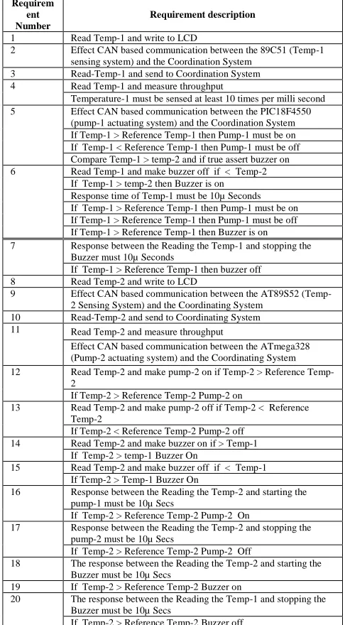
[image:4.612.328.571.160.600.2]networking of embedded systems becomes one of the most critical issues when it comes to the distributed embedded systems. One of the major issues that has been addressed is heterogeneity that exists among different types of microcontroller based systems which are used for developing and implementing different parts of a distributed embedded system. These requirements lead to the implementation of distributed embedded systems, each are nominated to monitor and control either the sensing or actuating mechanisms with the need for the centralised coordination among the distributed embedded systems. The functional requirements of the prototype system are shown in the Table 1.
Table 1
Functional Requirement specification of Prototype System
Requirem ent Number
Requirement description
1 Read Temp-1 and write to LCD
2 Effect CAN based communication between the 89C51 (Temp-1 sensing system) and the Coordination System
3 Read-Temp-1 and send to Coordination System 4 Read Temp-1 and measure throughput
Temperature-1 must be sensed at least 10 times per milli second 5 Effect CAN based communication between the PIC18F4550
(pump-1 actuating system) and the Coordination System If Temp-1 > Reference Temp-1 then Pump-1 must be on If Temp-1 < Reference Temp-1 then Pump-1 must be off Compare Temp-1 > temp-2 and if true assert buzzer on 6 Read Temp-1 and make buzzer off if < Temp-2
If Temp-1 > temp-2 then Buzzer is on Response time of Temp-1 must be 10µ Seconds If Temp-1 > Reference Temp-1 then Pump-1 must be on If Temp-1 > Reference Temp-1 then Pump-1 must be off If Temp-1 > Reference Temp-1 then Buzzer is on 7 Response between the Reading the Temp-1 and stopping the
Buzzer must 10µ Seconds
If Temp-1 > Reference Temp-1 then buzzer off 8 Read Temp-2 and write to LCD
9 Effect CAN based communication between the AT89S52 (Temp-2 Sensing System) and the Coordinating System
10 Read-Temp-2 and send to Coordinating System 11 Read Temp-2 and measure throughput
Effect CAN based communication between the ATmega328 (Pump-2 actuating system) and the Coordinating System 12 Read 2 and make pump-2 on if 2 > Reference
Temp-2
If Temp-2 > Reference Temp-2 Pump-2 on
13 Read Temp-2 and make pump-2 off if Temp-2 < Reference Temp-2
If Temp-2 < Reference Temp-2 Pump-2 off 14 Read Temp-2 and make buzzer on if > Temp-1
If Temp-2 > temp-1 Buzzer On
15 Read Temp-2 and make buzzer off if < Temp-1 If Temp-2 > Temp-1 Buzzer On
16 Response between the Reading the Temp-2 and starting the pump-1 must be 10µ Secs
If Temp-2 > Reference Temp-2 Pump-2 On
17 Response between the Reading the Temp-2 and stopping the pump-2 must be 10µ Secs
If Temp-2 > Reference Temp-2 Pump-2 Off
18 The response between the Reading the Temp-2 and starting the Buzzer must be 10µ Secs
19 If Temp-2 > Reference Temp-2 Buzzer on
20 The response between the Reading the Temp-1 and stopping the Buzzer must be 10µ Secs
International Journal of Emerging Technology and Advanced Engineering
Website: www.ijetae.com (ISSN 2250-2459, ISO 9001:2008 Certified Journal, Volume 8, Issue 12, December 2018)
[image:5.612.337.573.143.375.2]32
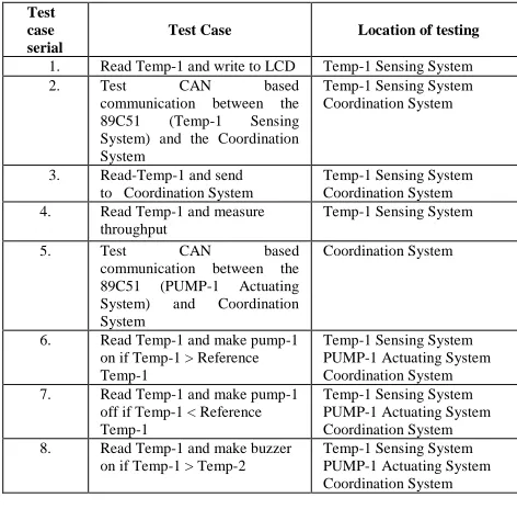
Different types of testing which must be carried to confirm that the functional requirements have been met by the system most appropriately are shown in Table-2. The test cases that are to be tested through Scaffolding method at Locations / Systems at which the testing must be carried are also shown in Table 2.Table 2
Testing Requirements for undertaking Testing of a Distributed Embedded System (Pilot Project)
III. RELATED WORKS
Control area network has a high performance and high reliable advanced serial communication protocol which supports distributed real time control. CAN has been effectively implemented to simplify communication between various modules [1] that are situated in an Automobile system. Converters are developed and used for converting communication from non-CAN native support to CAN. Not more attention has been made in speed matching and communication flow as required by the Application.
[2] Have implemented CAN based protocol which includes both static time-triggered and dynamic segment for high priority and low priority data transmission. D10 Bit of data segment are used to indicate the assignment of the messages for transmission either in low priority or in high priority mode. The communication has been designed to effect in the asynchronous mode. This protocol ensures that the crucial messages are sent out before their deadlines and one message hugs the bus. However, this protocol will lose one of the most important bits.
[3] Have implemented a CAN as an attractive alternative to automate different functions due to its ease, low cost and simplicity in implementation and as such reduces the complexity.
Test case serial
Test Case Location of testing
9. Read Temp-1 and make buzzer off if Temp-1 < Temp-2
Temp-1 Sensing System PUMP-1 Actuating System Coordination System 10. Test response between the
Reading the Temp-1 and starting the pump-1
Temp-1 Sensing System PUMP-1 Actuating System Coordination System 11. Test response between the
Reading the Temp-1 and stopping the pump-1
Temp-1 Sensing System PUMP-1 Actuating System Coordination System 12. Test response between the
Reading the Temp-1 and starting the Buzzer
Temp-1 Sensing System Coordination System
13. Test response between the Reading the Temp-1 and stopping the Buzzer
Temp-1 Sensing System Coordination System
14 Read Temp-2 and measure throughput
Temp-2 Sensing System
15. Test the RS485 based communication between the 89C51 (PUMP-2 Actuating System) and the Coordination System
Temp-2 Sensing System
16. Read Temp-2 and make pump-2 on if 2 > Reference Temp-2
Temp-2 Sensing System PUMP-2 Actuating System Coordination System 17. Read Temp-2 and make pump-2
off if 2 < Reference Temp-2
Temp-2 Sensing System PUMP-2 Actuating System Coordination System 18. Read Temp-2 and make buzzer
on if Temp-2 > Temp-1
Temp-2 Sensing System Coordination System 19. Read Temp-2 and make buzzer
off if Temp-2 < Temp-1
Temp-2 Sensing System PUMP-2 Actuating System Coordination System 20. Test response between the
Reading the Temp-2 and starting the pump-1
Temp-2 Sensing System
21. Test response between the Reading the Temp-2 and stopping the pump-2
Temp-2 Sensing System PUMP-2 Actuating System Coordination System 22. Test response between the
Reading the Temp-2 and starting the Buzzer
Temp-2 Sensing System Coordination System
23. Test response between the Reading the Temp-2 and stopping the Buzzer
Temp-2 Sensing System Coordination System
Test case serial
Test Case Location of testing
1. Read Temp-1 and write to LCD Temp-1 Sensing System 2. Test CAN based
communication between the 89C51 (Temp-1 Sensing System) and the Coordination System
Temp-1 Sensing System Coordination System
3. Read-Temp-1 and send to Coordination System
Temp-1 Sensing System Coordination System 4. Read Temp-1 and measure
throughput
Temp-1 Sensing System
5. Test CAN based communication between the 89C51 (PUMP-1 Actuating System) and Coordination System
Coordination System
6. Read Temp-1 and make pump-1 on if Temp-1 > Reference Temp-1
Temp-1 Sensing System PUMP-1 Actuating System Coordination System 7. Read Temp-1 and make pump-1
off if Temp-1 < Reference Temp-1
Temp-1 Sensing System PUMP-1 Actuating System Coordination System 8. Read Temp-1 and make buzzer
on if Temp-1 > Temp-2
International Journal of Emerging Technology and Advanced Engineering
Website: www.ijetae.com (ISSN 2250-2459, ISO 9001:2008 Certified Journal, Volume 8, Issue 12, December 2018)
33
The CAN system works effectively in the presence of electrical and mechanical interferences with the signals that are used by CAN by adapting different kinds of terminating techniques. Has implemented a project based on PIC technology which uses CAN for monitoring various parameters such as temperature CO level etc. Real time aspects have not been considered in the design of the project.CAN is making inroads in to every sector. CAN protocol has disadvantage that is the low priority devices cannot transmit data for long periods due to low priority that are attached to the devices at the time of interfacing the devices to the network. [4] Have presented two priority schemes which includes a round-robin scheme-based priority which will give the access to the bus in round robin fashion. The schemes have given an opportunity to low priority devices to transmit. The second scheme represents the least recently used priority. The priority of the nodes was rotated based upon the amount of usage of the BUS. The schemes that are proposed are applied at every node which avoids the use of any explicit master node or the message scheduler to provide an equal opportunity to all the nodes. The proposed schemes do not require any changes at physical and data-link layers of CAN protocol. Emergency state has been considered which allows a particular node to have provision of emergency states for gaining the access to the bus.
[5] Programmable logic controllers are most frequently used in the process industries. Faults have been recognized
when PLCs are used while using RS485 network. PLCs are
implemented by using 32 Bit Microcontrollers and the interconnectivity between the PLCs is through CAN (TJA1050T) interface, as CAN is found out to be noise free. Each PLC is built by using the Microcontroller based system works like an intelligent node. Several anti-interference are measured by designing appropriate terminating systems that are presented.
CAN based networking is widely in use and it extends across several domains. However, CAN cannot be used for some specific domains such as Dependable systems. CAN enhance Layer (CANELy) [6] architecture has been presented for supporting highly dependable systems. This architecture provides the analytic models of CAN operation, based on that both the hardware and software mechanisms for dependable and timely CAN-based network service necessities are implemented. The mapping of the error monitoring and fault-confinement mechanisms defined by CANELy are into hardware has been proven to be resource-effective, allowing their integration in an inexpensive Field Programmable Gate Array (FPGA) device.
This opened room is for cost-effective high
dependability CAN-based solutions in several domains, such as aerospace industry.
CAN based systems are being used frequently for home automation to help the elderly and disabled persons for making their own living. CAN helps in establishing a network of home appliances by using three sub-systems
namely Central Controller Subsystem (CCS) [7], CAN
module sub-system and relay module sub-system. The central Controller Sub-System is a simple server which provides Graphical user interface. The CAN module which is connected to CCS acts as master and the CAN modules which are connected to the home appliances acts as slaves. Master CAN and Slave CAN modules are connected by using a CAN bus. The user input signal which contains CAN data frame broadcasts from master CAN node to all slave CAN nodes via CAN bus. Each data frame has an identifier that is compared by each slave CAN node. The signal will be discarded by the slave CAN node if the identifier is not matched, or else, the slave CAN node will decode the data frame and execute the given command. The relay module in the slave CAN node will either switch ‘ON’ or ‘OFF’ by the corresponding home appliances.
The nodes that are interfaced to a CAN bus uses FIFO or priority queues for stacking the messages which are transmitted periodically or sporadically. Some high-level protocols such as CANopen, Hagglunds which are termed as HCAN [8] supports the transmission of mixed messages. With the use of HCAN the existing response-time analysis of mixed type CAN messages can be extended. The extended analysis can compute the response-times of the mixed (periodic/ sporadic) messages in the CAN network where some nodes use FIFO queues while others use priority queues.
A multi-motor control circuit can be implemented by using CAN. The motor systems which is breakdown is controlled through a Microcontroller based system and DAC [9] which are interfaced to a CAN bus. The Multi-control motor system is interfaced with a CAN bus. Overall structure of the system of hardware design, software design process, and CAN bus controller structure together where implemented will help in implementing multi Motor control system.
International Journal of Emerging Technology and Advanced Engineering
Website: www.ijetae.com (ISSN 2250-2459, ISO 9001:2008 Certified Journal, Volume 8, Issue 12, December 2018)
34
Based on the comparative analysis of implementation of time- triggered systems using star and bus topology has been done and it proved that the star topology is efficient when implemented through a Modified S-C algorithm.Shared Clock (S-C) algorithms are used in conjunction with off-the-shelf microcontrollers-based systems in the development of distributed embedded systems. All the SC designs are based on BUS topology. A novel SC algorithm [11] uses star topology for establishing a distributed embedded system. Through a fault-injection case study and quantitative comparisons, it is proved that the star-based design has several advantages when compared with a bus-based equivalent.
The Controller Area Network (CAN) protocol are a real-time, serial, broadcast protocol has a very high level of security. The AT90CANl28 CAN controller is fully compatible with the CAN specification but the internal structure of it is different from independent CAN controllers. A method [12] is been presented in order to set the baud rate and other parameters within AT90CAN128 CAN controller so that the communication can be properly affected through the CAN Module.
CAN bus are being used more and more in wide range of applications for its superiority, but CAN can’t be used directly to communicate with a PC. Converting RS232 to CAN bus protocol will help in connecting a PC to a CAN network. A converter is presented [13] using a
PIC18F2580 Microcontroller and SJA1000 CAN
controller which are used for establishing communication between a PC and a Microcontroller based system.
A controller area network (CAN) is ideally suited for many high-level industrial protocols embracing CAN and ISO 11898 as their physical layer. Wonderful elasticity in system design can be implemented considering the cost, performance, and Upgradeability A brief introduction to the CAN operating principles and the implementation of a basic CAN bus using Texas instrument’s, CAN transceivers and DSPs, are been presented [14]. A discussion on the error detection and fault confinement mechanisms are also been presented. The CAN is also been extended called as eCAN and the properties of the same
have also been presented.
[15] A new system design which uses CAN2.0B
specification are presented. The system design focusses on hardware and software design of intelligent node which are built using a Microcontroller S3C44B0, MCP2510 CAN controller, which is a Full CAN protocol controller implementing CAN specification V2.0 A/B and receive the standard and extended messages. In addition, the TJA1050 is used as an interface between the Controller Area Network (CAN) protocol controller and the physical bus.
A fixed priority DM algorithm is used for assigning the priority for each message and for getting a better result. In software, UC/OS-II multitasking operating system is used by which a real time operating system suits for industrial control and better than anyone else.
In all the literature references, developing a CAN based
network using heterogeneous microcontroller-based
systems are not been presented. The message flow system specific to an embedded distributed application has not been discussed much. Nobody had said about the issue of arbitration by considering the sequence of messages as required by the distributed application. [16] The design of datagrams that must be transmitted commensuration to the expected message flow did not explain.
Automation of automobile systems involves in use of numerous processing systems with built-in control mechanisms [17]. Model based designs are used for reducing the time for development for such large-scale systems. Testing of such kind of large systems can be done by using a wide area-based test environment system. A middleware system which is installed on a node of a wide area network shall control the process of undertaking the testing. A model-based agent simulation system is used to show the way how the testing is carried.
[18] Has proposed a testing method which is based on selection of test data through the analysis of data flow, and through the failure analysis which is carried based on several test Oracles. The testing is carried by observing the actual behavior and by comparing the same with expected behavior. The test data are collected based on the interaction points of various functions. This approach however does not deal anything related to distributed and interconnected embedded systems.
An embedded system which automates the operations of an automobile system which are reactive system, fewer inputs arises and the domain of such inputs are very small in making it to pick an input value through the process of randomization [19]. The important issue is that long sequences of interaction between the processes should also be tested. The effectiveness of selected test cases against the selected test cases based on the logic is also carried. This kind of testing is also be used for testing distributed embedded systems but as a whole cannot be considered for testing a distributed embedded system.
International Journal of Emerging Technology and Advanced Engineering
Website: www.ijetae.com (ISSN 2250-2459, ISO 9001:2008 Certified Journal, Volume 8, Issue 12, December 2018)
35
[21] Have proposed a simulating tool for simulating a highly configurable hardware for software testing. Real time networks could be simulated using the simulator (DESSE) which simulates the testing environment. The simulator will simulate a distributed embedded network using a full-duplex fast Ethernet. Using the simulator all kinds of tests can be done using scripts.Testing huge number of individual embedded systems simultaneously are mostly needed for reducing the time required for testing millions of embedded pieces developed out of the same embedded systems. [22] has used master slave system in which a PC is used as a HOST for undertaking the testing. For mass device testing, RS485 networking is used. The arrangement is been used for undertaking individual device testing and for not the testing of distributed embedded systems itself.
Environment setting is very important for undertaking testing of any type of embedded system [23]. The basics of the environment setting must be analyzed by considering the basic structure, functionalities and characteristics of distributed software. A three-layer structure has been proposed which facilitates the setting for appropriate test environment. This kind of proposal is quite difficult to implement, and it is not possible to order a structure for the development of individual applications within a distributed embedded system.
Interconnection of distributed embedded systems is error prone due to the presence of many complex issues. Individual embedded systems may be error free and becomes error prone as they get connected to a network. Many methods are being used for undertaking the automated testing for tracing out the bugs which are existing in the working of distributed embedded systems. [24] have proposed cause and effect graphs which are time dependent to describe the test cases by considering the distribution and real time properties. Test object structure is used for undertaking the testing in-depth. They have proposed a simple language describing test objects which consists of modules and connections. The language that enables graphical documentation and context-sensitive protocol analysis. Symbolic representation of received messages facilitates a better comprehension of system behavior.
[25] Have proposed an efficient architecture for the
development of rapid, reliable, decentralized and collaborative applications for the large scale, high-performance, distributed, real-time and embedded systems which have inbuilt test enablement processes in it. The Architecture is called as TENA (Testing and Training enablement architecture.
TENA has a built-in middleware that precisely weaves together a unique combination of model-driven, code-generated software with high-level, which is easy to understand programming abstractions and an API that is designed to detect programming errors at the compile-time rather than at run-time, where the cost of an error could be extremely high. TENA provides standardized re-usable components to simplify the development of TENA applications. TENA features are flexible and extensible. TENA Object Model Compiler (OMC) can automatically generates example programs, test programs, and gateways to legacy systems with older, less sophisticated software architectures such as Distributed Interactive Simulation (DIS) and the High-Level Architecture Run-time Infrastructure (HLA/RTI). TENA supports many major test and training events. This approach is more towards in finding the errors at compilation time than when the distributed embedded system is running. Developing such compiler is very complex.
International Journal of Emerging Technology and Advanced Engineering
Website: www.ijetae.com (ISSN 2250-2459, ISO 9001:2008 Certified Journal, Volume 8, Issue 12, December 2018)
36
[28] Have proposed a simulation technology which aims to improve the development and testing of distributed, CAN-based, embedded real-time control-systems. With the help of simulator, a complete control-system can be developed and tested without or with only partial, access to target hardware. This is achieved by replacing target hardware dependent operations (e.g. device driver and operating system calls) with simulated equivalences which allows execution in a regular PC based environment. Thus, the powerful PC tools for debugging, automated testing, fault injections, and dynamic modelling of the target machine, are available for the embedded systems engineer. Complex dynamic behaviors can be considered in the simulated environment, without access to the target hardware, e.g. allowing single stepping through the scenarios. Simulating the entire system also facilitates the customer tests and the end-user evaluation of the system in an early phase of system development. The turnaround time for change, test, and evaluation are shorten, because development can be performed on a single PC instead of a full target system.[29] A test architecture has been represented that aims
transmitting JTAG signals over a serial channel. The
architecture has been developed to facilitate system testing and automatic field by updating the distributed base stations situated in a wireless network. Test architectures assumes that the distributed base stations are on the same back pane and on the same chassis. The architecture
considers the use of boundary SCAN software which runs
by the processor situated within a wireless sensor node.
The nodes are configured by the SCAN software for
receiving instructions from a remote location. The SCAN
software will be able to conduct a system test and find if any system errors exists.
Many distributed embedded systems are built by using the fault tolerance concepts. One of the main challenges is to find the errors which occurs while the distributed embedded systems are in run-state. At any level faults can occur. The faults can occur at PIN level which normally effect the network interfaces and the communication that is built to facilitate the communication between various distributed nodes which are networked. Architecture is proposed [30] by considering the use of monitor, that keeps monitoring the faults which occur at PIN level. The monitor is developed to observe the system behavior and to detect whether any failure has occurred at any of the PIN.
Testing distributed system is more difficult due to issues like interoperability, collaboration, synchronization, timing, and concurrency. A tester often must spend significant time in developing lengthy testing code to confirm that the System under Test (SUT) is reasonably well tested.
An object-oriented framework [31] is proposed for testing distributed system rapidly and adaptively by using scenario modelling, state modelling, verification patterns, design patterns, regression testing, ripple effect analysis, simulation, automated test execution, and remote testing by using TCP/IIP or SOAP.
Now-a-days most modern applications are distributed. Testing distributed applications is complex. The distributed applications are generally component based and exhibit a dynamic behavior. Dynamic interaction, structural behavior, run-time configurations etc. makes the testing of distributed systems as complicated. It has been proved that time and gain that any amount of testing is carried on the developed product; some unknown errors are identified during the production time. Therefore, it is necessary that the testing be done while distributed embedded systems are
in the production phase. [32] Therefore there is a need to
develop concepts and methods by which a distributed system is tested while the system is in running mode. Online testing of distributed embedded systems is necessary. Online testing will help in undertaking the testing of functionality within the limited time, resources available, complex transactions are also performed between the components.
Many real-time systems change over time due to new requirements and technology improvements. Each revision requires regression testing to confirm that existing functionality is not affected by such changes. Testing these systems are often requires specialized hardware and software, and both are expensive. While the overall regression testing process is same across different organizations, the strategies and tools used by them varies according to their product needs. Hence a good framework for regression testing should be provided, and there should be a flexibility to configure it depending on the organization’s needs and at the same time maximizing the utilization. Manual processes are typically slow and error-prone, and the results are under-utilization of valuable test resources. An automated distributed regression testing framework provides the flexibility to the user for configuring it to their needs while at the same time optimizing resource usage has been presented [33].
One method is simulation which is frequently used for testing distributed embedded systems. Simulation software is distributed over a set of smaller, inexpensive computers, in lieu of a traditional mainframe that has been shown to dramatically reduce the cost of building real-time simulation architecture. A true distributed architecture is
more cost effective than the latest generation
International Journal of Emerging Technology and Advanced Engineering
Website: www.ijetae.com (ISSN 2250-2459, ISO 9001:2008 Certified Journal, Volume 8, Issue 12, December 2018)
37
An Advanced Multi-Purpose Support Environment (AMPSE) is architecture and design methodology for distributed real-time simulation which has been presented [34]. It is a generic architecture which emphasizes on modularity, configurability, expandability, and software reuse. Other recent attempts for distributed real-timesimulation systems have encountered significant
performance difficulties due to inefficiencies in the
approaches that are used for inter-processor
communications and for scheduling and coordination of the distributed software execution.
[35] have presented the way how the testing of distributed system is achieved through scaffolding method
by using a repository of master test cases
.
[36] have presented the way how the distributed embedded system is connected through RS485 network.
IV. INVESTIGATIONS AND FINDINGS
A. Networking of heterogeneous Embedded Systems The CAN based networks are chosen for the application which contains a single master and 4 slaves. Conversion mechanisms are to be considered when the microcontroller systems which are used are part of network is heterogeneous due to the reason that they do not have native CAN interface.
As per the functional requirements of an application, LPC2148 a 32-Bit Microcontroller is used as coordinating system for achieving communication between the slave devices and the master. The master device must be designed to alert local user through triggering a Buzzer about the variations that takes place with the temperature gradients. The master system is to be designed for interfacing with a PC for communicating with it to obtain the reference temperatures and transmitting the process data to be stored in a database.
4-slave microcontroller based devices namely 89C51, AT89S52, PIC18F4550 and ATmega328 have been considered for implementing various functions which are
projected as requirements by including sensing
temperature-1, sensing temperature-2, starting and stopping pump-1, starting and stopping pump-2. In those slave systems 89C51 and AT89S52 don’t have the CAN support. conversion mechanisms are required for interconnecting these systems. 89C51 and AT89S52 have been designed with inbuilt RS232C communication interfaces. A device CAN / CAN open / RS232 – Converter has been used for converting RS232C signals to CAN and Vice Versa.
The other 2 microcontroller-based systems namely PIC18F4550 has built-in SPI interface which is to be converted into CAN using the converter SPI-CAN and with
the Microcontroller ATmega328, the built-in I2C must be
converted to CAN using a converter. Thus, the
heterogeneity that exists due to varying in interfaces for communication are tackled through choice of appropriate converters. The application specific communication requirement requires the transfer of data at the rate of 19K which is supported by means of any.
B. Architectural design for Message flow across the distributed embedded systems (pilot project)
The networking diagram shown in the [Figure 1] shows
the interfacing of the various heterogeneous
microcontrollers based systems which are interconnected through a CAN based protocol system. However
communication software resident in different
microcontroller based system is required for achieving application specific messaging requirements using the network designed for the purpose.
The communication must be initiated by the master by using RTR (Remote transmission request) for want of Temperature-1 and Temperature-2 to be transmitted by 89c51 and AT89s52 in that sequence. The throughput, sequencing and timing of receipt of the temperatures are designed and developed into master device. The applications on 89C51 and AT89S52 will have software components to receive the master requests and transmit the data to the master device. The communication components implement RS232C serial communication system for transmitting and receiving the temperature data.
International Journal of Emerging Technology and Advanced Engineering
Website: www.ijetae.com (ISSN 2250-2459, ISO 9001:2008 Certified Journal, Volume 8, Issue 12, December 2018)
38
The master also is provided with a component that computes the temperature gradient and asserts a buzzer or otherwise if the temperature gradient is beyond the prescribed limits. This function as such requires no communication as the entire functioning is implemented within the master device.
The software architecture that depicts the application
specific communication is shown in the [Fig. 2]
CAN Tran – T1
CAN Recv – T1
CAN Tran – T2
CAN Recv – T2 RS232C
Tran – PC Recv – T1RS232C
CAN Tran – P1
CAN Recv – p1
CAN Tran – P2
CAN Recv – p2
RS232C
Tran – PC Recv – T1RS232C PC Application
M A S T E R A P P L I C A T I O N RS232C
Tran – T1
RS232C Recv – T1 T1 Application
CAN Tran – P1
CAN Recv – P1
P1 Application RS232C Tran – T2
RS232C Recv – T2
T2 Application
CAN Tran – P2
[image:11.612.338.544.132.354.2]CAN Recv – P2 P2 Application
Fig. 2 Communication system Architecture
It can be seen from the Figure-1 that the coordinating system has been provided with necessary interfaces for
effecting CAN based communication with other
microcontrollers which use a different interface all together.
C. Process flow for undertaking testing through scaffolding:
Figure 3 shows the process that is involved in undertaking testing at a Location. Test scripts are generated in order to do testing at a distributed location for undertaking comprehensive testing of distributed embedded system. The test scripts are generated by mapping of test cases with the commands which are mapped with different types of arguments. The generated test cases are written into an OS file called Test Script file. The following algorithm is used for generating test scripts
Algorithm for test script generation:
Do the following process for each of test case to which the commands are mapped.
a. Select a Test case
b. Select Script commands related the test cases
c. Select the arguments related to the command
i. For each of the argument, select
argument type and value range that can be used for selecting a value for the argument
ii. Select value for the argument by using a
process of randomization
d. Generate the script
Parser
Parser
Script Generator
Script Generator
Test SCript Split Mapped Test
Cases
Sooffolded Software Source Code
Scaffolding
Scaffolding
Test Commands
Code, Commands Mapping
Code, Commands Mapping
Mapped code with Commands
Test Results – Audit Trail
[image:11.612.57.281.232.392.2]Comm
Figure 3 Process flow for testing at a Location using the method scaffolding
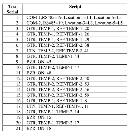
The test scripts are generated for the selected test cases by using the algorithm described above and the same are
shown in the Table 3. The test scripts are processed
through a parser which is compiled into scaffolder ES software.
Table 3 Generated Test Scripts
Test Serial
Script
1. :COM-1,RS485=19, Location-1=L1, Location-5=L5
2. :COM-2, RS485=19, Location-3=L3, Location-5=L5
3. :GTR, TEMP-1, REF-TEMP-1, 20
4. :GTR, TEMP-1, REF-TEMP-1, 26
5. :GTR, TEMP-1, REF-TEMP-1, 29
6. :GTR, TEMP-2, REF-TEMP-2, 38
7. :LTN, TEMP-2, REF-TEMP-2, 41
8. :GTR, TEMP-2, TEMP-1, 44
9. :BZR, ON, 45
10. :GTR, TEMP-2, TEMP-1, 47
11. :BZR, ON, 48
12. :GTR, TEMP-2, REF-TEMP-2, 50
13. :GTR, TEMP-2, REF-TEMP-2, 53
14. :GTR, TEMP-2, REF-TEMP-2, 56
15. :GTR, TEMP-2, REF-TEMP-2, 59
16. :GTR, TEMP-1, REF-TEMP-1, 8
17. :LTN, TEMP-1, REF-TEMP-1, 11
18. :GTR, TEMP-1, TEMP-2, 14
19. :BZR, ON, 15
20. :GTR, TEMP-1, TEMP-2, 17
[image:11.612.345.567.460.689.2]International Journal of Emerging Technology and Advanced Engineering
Website: www.ijetae.com (ISSN 2250-2459, ISO 9001:2008 Certified Journal, Volume 8, Issue 12, December 2018)
39
D. Undertaking testing at Individual Locations throughScaffolding
80% of the ES code is hardware independent code and therefore it is tested on HOST, the computer on which ES code is developed, cross compiled, linked and code relocated, and the remaining code is Hardware dependent code. The hardware dependent code can be scoffolded to simulate the behavior of the hardware there by making it to be hardware independent code. Thus, the entire code can be made to be hardware independent code so that the code can be compiled, linked and executed on the HOST. A separate software component is added to the ES application which will facilitate the testing of the code by using the test scripts generated by following a different process.
The scaffolded software must be able to call the interrupt service routines to simulate the occurrence of events from the hardware devices, must be able to call timer related functions for managing the passage of time etc. Using the scaffolding software several test cases can be inputted for testing individual program units. Integration between the program units, testing of occurrence of external events, testing of passage of time etc., are accepted by using scaffolding.
Scaffolding mechanism become complicated when the scoffolded input at one embedded system generates it as a scaffold output into another embedded system, in this case the scaffolding software running on a different distributed embedded system must communicate with each other. While one ES system scaffolds an input device the other should scaffolds the output device. Scaffolding technique are used for undertaking unit testing, event based and time-based integration testing when the processes related to them are distributed to be located at different embedded systems. The scaffold software which is located on either of the embedded systems must be able to communicate with the inputs and recording of the output consequent to undertaking the testing.
E. Undertaking testing through parser
[image:12.612.341.540.146.268.2]A parser is added to the scaffolded code which can read the script file. Parser can read a test script from the script file, parses the command and its related arguments. By using the command, parser fetches the list of functions and the sequence of functions to be executed. The parsers create a pointer to the function and enters the functions in a priority queue. Another process fetches the pointer from the queue and keeps executing the functions and writes the output along with the test case to the audit trail. The working of parsing and queue processing is shown in the figure 5.
Figure 5 Testing embedded systems through parsing and queue processing
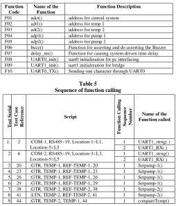
The ES application consists of set of functions and the functions must be called in a sequence at any of the distributed locations for undertaking testing of a test case. For each testing that to be carried out, the sequence in which the functions must be called is mapped and stored in
a repository. Table 4 shows a sample of functions that
comprise the Coordination system. The sequence in which the functions must be called for test case to be performed is
shown in the Table 5.
Table 4
List of functions that comprise the Central application
Function Code
Name of the Function
Function Description
F01 adct() address for central system F02 adt1() address for temp 1 F03 adt2() address for temp 2 F04 adp1() address for pump 1 F05 adp2() address for pump 2
[image:12.612.317.571.427.725.2]F06 buzz() Function for asserting and de-asserting the Buzzer F07 delay_ms() Function for causing system driven time delay F08 UART0_init() uart0 initialization for pc interfacing F09 UART1_init() uart1 initialization for bridge F10 UART0_TX() Sending one character through UART0
Table 5 Sequence of function calling
T
es
t
S
er
ial
T
es
t
Cas
e
Re
fe
re
n
ce
Script
F
u
n
ct
io
n
Calli
n
g
S
eq
u
e
n
ce
Num
b
er
Name of the Function called
1. 2 :COM-1, RS485=19, Location-1=L1, Location-5=L5
1 UART1_strng( ) 2 UART1_RX( ) 2. 6 :COM-2, RS485=19, Location-3=L3,
Location-5=L5
1 UART1_strng() 2 UART1_RX( ) 3. 20 :GTR, TEMP-1, REF-TEMP-1, 20 1 Setpump-1() 4. 23 :GTR, TEMP-1, REF-TEMP-1, 23 1 Setpump-1() 5. 26 :GTR, TEMP-1, REF-TEMP-1, 26 1 Setpump-1() 6. 29 :GTR, TEMP-1, REF-TEMP-1, 29 1 Setpump-1() 7. 38 :GTR, TEMP-2, REF-TEMP-2, 38 1 Setpump-2() 8. 41 :LTN, TEMP-2, REF-TEMP-2, 41 1 Setpump-2() 9. 44 :GTR, TEMP-2, TEMP-1, 44 1 compareTemp()
PARSER
PARSER
SCRIPT File
SCRIPT File
Function Repository
Function Repository
Function queue
Function queue
Queue Processor
Queue Processor Test CasesTest Cases
Audit Trail
International Journal of Emerging Technology and Advanced Engineering
Website: www.ijetae.com (ISSN 2250-2459, ISO 9001:2008 Certified Journal, Volume 8, Issue 12, December 2018)
40
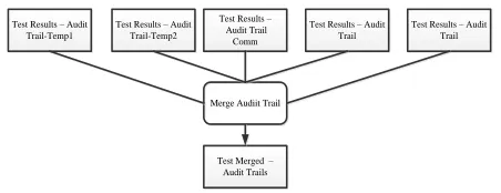
To the scaffolded code a parser is added which reads a test script from the script file, parses the command and its related arguments. Using the command, the parser fetches the functions from the list and the sequence of the functions to be executed. The function pointers are added into a queue. Another process reads from the queue and executes the functions. The functions are called by arguments that are passed to the commands. The execution of function that leads to completing the testing and generation of test results. The test results obtained after testing by following the above process are written to audit trail are shown as experimental results.F. Merging Test results and producing an audit trail The test results obtained from each of the scaffolding are undertaken at distributed computing locations and are merged based on the test case serial which are originally identified as a set of testing requirements. The process of merging the test results which are obtained by conducting testing by using the scaffolding method at each of the
distributed locations are shown in the Figure 6.
Test Results – Audit Trail
Comm Test Results – Audit
Trail-Temp1
Test Results – Audit Trail-Temp2
Test Results – Audit Trail
Test Results – Audit Trail
Merge Audiit Trail Merge Audiit Trail
[image:13.612.326.567.133.283.2]Test Merged – Audit Trails
Figure 6 Merging the test results obtained from scaffolding at each of the location
The test results which are obtained due to merging, are represented across the entire distributed embedded system is shown in the Experimental results.
V. EXPERIMENTAL RESULTS
Experiments have been conducted using the CAN network designed and the distributed embedded application system & the communication system implemented. Communication is effected by making the data flow as per the communication system architecture. The results of the
experimenting conducted are shown in the Table 6. The
experimental results have also been validated by using PROTEUS simulator.
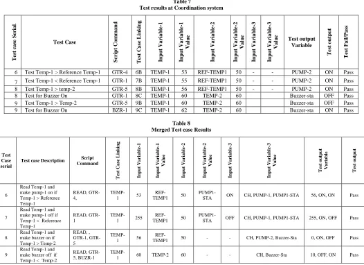
Experiments are conducted for converting original code into scaffolded code and tests the ES code. The test results that are generated after testing the application at
Coordination system is shown in the Table 7. The merged
Test results considering the entire application have been
[image:13.612.55.281.377.464.2]shown in Table 8.
Table 6 Experimental results
T
ran
sac
tion
I
D
From To
Wh
e
th
er
C
h
ec
k
su
m
e
rr
or
e
xi
sts
Micro-controller
system Micro-controller system Identifier
N
u
mb
e
r
of
b
yt
e
s
se
n
t
Micro-controller
system
Micro-controller system Identifier
N
u
mb
e
r
of
b
yt
e
s
R
e
ce
iv
e
d
1 89C51 11010101001 2 LPC2148 11010101000 2 No
2 AT89S52 11010101011 2 LPC2148 11010101000 2 No
3 LPC2148 11010101000 1 PIC18F4550 11010101100 1 No
4 LPC2148 11010101000 1 ATmega328 11010101110 1 No
VI. CONCLUSIONS
Networking of distributed embedded systems are undertaken by using CAN protocols. Hardware converters are used for converting native interfaces to CAN interfaces. Message flow across the distributed embedded system also varies from application to application and therefore there is a need that to be designed separately. Sequencing of message flow is required, and the sequence flow of messages can be controlled through setting appropriate identifiers to the devices for arbitrating the bus. Data packets are to be signed by considering the sequence of flow of data and there needs to be designed accordingly.
The standard methods like scaffolding, Assert Macros etc., are in existence as on today using which the testing of standalone embedded systems is being carried must be modified and new methods must be invented for undertaking the testing of distributed embedded systems. The investigations that are presented in this paper are related to breaking single test cases that must be tested across entire distributed embedded system into many test cases that each of the test cases can be generated by testing at a specific individual embedded system. The test results obtained at each location is integrated through mapping and merging so that the overall status of testing the entire distributed embedded system. The process of undertaking testing through scaffolding is presented in this paper.
REFERENCES
[1] Mansi Desai, Rahul Shetty, Viraj Padte, Mayur Parulekar, Samuel
Ramrajkar. Controller Area Network for Intelligent Vehicular Systems. IEEE conference publications. 2013; 1-6.
[2] Chin-Long Wey, Chung-Hsien Hsu, Kun-Chun Chang, and
Ping-Chang Jui. Enhancement of Controller Area Network (CAN) Bus Arbitration Mechanism. International Conference on Connected Vehicles and Expo (ICCVE). 2013; 898-902.
[3] Presi.T.P. Design and Development Of PIC Microcontroller Based
International Journal of Emerging Technology and Advanced Engineering
Website: www.ijetae.com (ISSN 2250-2459, ISO 9001:2008 Certified Journal, Volume 8, Issue 12, December 2018)
41
[4] Pranjal Vyas, Swaroop A. Hangal, Leena Vachhani.Methods for
equitable distribution of bus access among nodes of Controller Area Network. IEEE Conference Publications. 2012; 1-6.
[5] Jinshui Shi. The Implementation of CAN Bus Network of PLC
Based on ARM. 4th International Conference on Intelligent Human-Machine Systems and Cybernetic. 2012; 1:268-270.
[6] Ricardo Pinto, Jose Rufino, Carlos Almeida. High Availability in
Controller Area Networks. IEEE Conference Publications. 2011; 1-6.
[7] Kent How Teh, Wei Lun Ng, Chee Kyun Ng and Nor Kamariah
Noordin. Home Appliances Management System using Controller Area Network (CAN). 17th Asia-Pacific Conference on Communications (APCC). 2011; 899-904.
[8] Saad Mubeen, Jukka Maki-Turja and Mikael Sjodin. Extending
Response –Time Analysis of Controller Area Network (CAN) with FIFO Queues for Mixed Messages.IEEE Conference Publications. 2011; 1-4.
[9] Shanshan Wang, Bo Yin, He Li, Qingshu Yang. Multi-motor
Control System Design Based on Can Bus. International Conference on Electronic & Mechanical Engineering and Information Technology. 2011; 4910-4913.
[10] Amir Muhammad, Michael J. Pont. A Time-Triggered
Communication Protocol for CAN-based Networks with a Fault-Tolerant Star Topology. IEEE Conference Publications. 2010; 2347-2354.
[11] Amir Muhammad, Devaraj Ayavoo, Michael J. Pont. A Novel
Shared-Clock Scheduling Protocol for Fault-Confinement in
CAN-based Distributed Systems 5th International Conference on System
of Systems Engineering. 2010; 1-6.
[12] MinLi, Suo-liang Zhang, Cheng-hao Han, Zhi Ca. The CAN Bus
Baud Rate Setting Method Based on AT90CAN128. International Conference on Computer, Mechatronics, Control and Electronic Engineering.2010;3:542-545.
[13] Xianjun Wang & Wencheng Guo. The Design of RS232 and CAN
Protocol Converter based on PIC MCU. Computer and international science journal.2009;2:3:176-181.
[14] Hanxing Chen, Jun Tian. Research on the Controller Area Network.
IEEE Conference Publications.2009;2:251-254.
[15] Yanxia Liu, Shufen Li, Yuqiu Song. Application of can-bus in
embedded vehicle body control system. IEEE Conference Publications. 2009;2: 261-264.
[16] Dr. JKR Sastry, M Vijaya lakshmi, J Sasi Bhanu. Optimizing
Communication between heterogeneous distributed Embedded Systems using CAN protocol. ARPN Journal of Engineering and Applied Sciences. Vol. 10, No. 18, October 2015. 7900-7911.
[17] YukikazuNakamoto, Tadahiro Ito, Kenji. Wide area distributed
Integrated Test Environments for Distributed embedded control system. IEEE 17th International Symposium. 2014; 174-179.
[18] TingtingYua, AhyoungSungb, WitawasSrisa-ana, Gregg
Rothermela. An approach to testing commercial embedded systems. Science Direct. 2014; 207-230.
[19] Venkatesh, Prasad Bokil, TukaramMuske, Vijay Suman.
Effectiveness of Random Testing of Embedded Systems. 45th Hawaii International Conference. 2012; 5556-5563.
[20] Valentin Chimisliu , Franz Wotawa. Model Based Test Case
Generation for Distributed Embedded Systems. IEEE Conference Publications. 2012; 656-661.
[21] Hui Liu, MaozhongJin, Chao Liu. Construction of the Simulating
Environment for Testing Distributed Embedded Software. 5th International Conference. 2010; 97-101.
[22] Yanfang Wang, Wandui Mao, Jinying Li, Peng Zhang, Xiaoping
Wang. A Distributed Rectifier Testing System Based on RS-485. IEEE Conference Publications. 2010; 779-781.
[23] Pei Tian, JianchengWang, HuaijingLeng, Kai Qiang. Construction of
Distributed Embedded Software Testing Environment. IEEE Conference Publications. 2009; 1: 470-473.
[24] Silvije Jovalekic, Bernd Rist. Test Automation of Distributed
Embedded Systems based on Test object Structure Information. IEEE Conference Publications. 2008; 343-347.
[25] J. Russell Noseworthy. The Test and Training Enabling Architecture
(TENA) —Supporting the Decentralized Development of
Distributed Applications and LVC Simulation. IEEE Conference Publications. 2008; 259-268.
[26] Dae-Hyun Kum, Joonwoo Son, Seon-bong Lee and Ivan Wilson.
Automated Testing for Automotive Embedded Systems. IEEE Conference Publications. 2006; 4414-4418.
[27] D.N. Ramos- Hernandeza, P.J. Fleminga, J.M. Bassb. A novel
object-oriented environment for distributed process control system. Science direct. 2005; 213-230.
[28] Anders Moeller, Per Aberg, Fredrik Loewenhielm, JakobBrundin,
Mikael Nolin, JakobEngblom. Developing and testing distributed CAN-based real-time control-systems using a single PC.iCC; 2005.
[29] Chen-Huan Chiang, Paul J. Wheatley, Kenneth Y. Ho, Ken L.
Cheung.Testing and Remote Field Update of Distributed Base Stations in a Wireless Network. IEEE Conference Publications. 2004; 711-718.
[30] Sara Blanc, Pedro .J.Gil. Improving the multiple errors detection
coverage in distributed embedded systems. IEEE Conference Publications. 2003; 303-312.
[31] W. T. Tsai, L. Yu, A. Saimi. Scenario-Based Object-Oriented Test
Frameworks for Testing Distributed Systems. IEEE Conference Publications. 2003; 288-294.
[32] Peter H. Deussen, George Din, Ina Schie ferdecker. An online Test
platform for component-based systems. IEEE Conference
Publications. 2002; 96-103.
[33] G. Walters, E. King, R. Kessinger, R. Fryer. Processor design and
implementation for Real-Time Testing of embedded systems. IEEE Conference Publications. 1998; 1: B44/1-B44/8.
[34] Steven A. Walters. Practical Techniques for Distributed real-time
Simulation. IEEE Conference Publications. 1994; 2: 890-896.
[35] K.Chaitanya, J.K.R.Sastry, K.Rajasekhara Rao,DBK Kamesh. An
Effective Model for Testing Distributed Embedded Systems using Scaffolding Method. Ponte International Journal of Sciences and Research. Vol. 73, No. 8, August 2017, 2-22.
[36] JKR Sastry, T. Naga Sai Tejasvi and J. Aparna. Dynamic scheduling