International Journal of Emerging Technology and Advanced Engineering
Website: www.ijetae.com (ISSN 2250-2459,ISO 9001:2008 Certified Journal, Volume 4, Issue 2, February 2014)
839
Mitigation and Analysis of Three Phase Transformer
Magnetizing Inrush Current By Using Point on Wave Switching
Method
Nilesh Deokar
1, Harpreet Singh
21PG Student, 2H.O.D & Associate Professor, IET, Alwar, Rajasthan
Abstract— Transformer is the most important equipment
of the electrical power system. At the time of transformer energization high current is drawn by the transformer known as the inrush current. This current is nearly ten times more than the full load current of transformer. It produces mechanical stress on transformer and also affects the windings and bushings of the transformer. The large switching transient current affects malfunction of protection system of power system and the different equipments connected to system. So the inrush current should be minimized. There are different methods used to minimize the inrush current such as volt second balance, series compensator, point on wave switching method etc. This paper focuses on point on wave switching method. It also explains the results for inrush current of three phase transformer with and without point on wave switching method. A test is driven on 450 kVA, 500kV/230kV grounded Y/D transformer in MATLAB/SIMLINK environment. It also focuses on power quality issues associated with transformer at no load condition.
Keywords— Transformer, point on wave switching,
MATLAB R2010a/SIMULINK.
I. INTRODUCTION
Transformer is used at transmission to step up the voltage level and at distribution to step down voltage. But there are some losses and affects due to transformer. Mainly inrush current is occurred in transformer. At the time of transformer energization, a high current will be drawn by the transformer [1][5][8]. The mentioned current is called transient inrush current and it may rise to ten times the nominal full load current of transformer during operation. Energization transients can produce mechanical stress to the transformer, causes protection system malfunction and it often affect the power system quality and may disrupt the operation of sensitive electrical loads such as computers and medical equipment connected to the system [1].
In this paper transient inrush current of transformer is discussed. Section II-III presents inrush current and its causes in transformer. Effect of inrush current on various electrical components is explained in section IV.
In section V, analysis of inrush current for three phase transformer is carried out in Matlab/Simulink environment. Finally a brief discussion and conclusion is drawn on
transformer inrush current in section VI-VII
.
II. INRUSH CURRENT
At the time of transformer energization, a high current will be drawn by the transformer. The mentioned current is called transient inrush current and it may rise to ten times the nominal full load current of transformer during
operation. Transformer inrush currents can be divided into
three categories, energization inrush, recovery inrush and sympathetic inrush. The first, energization inrush results from reapplication of system voltage to a transformer which has been previously de-energized. The second, recovery inrush occurs when transformer voltage is restored after having been reduced by a nearby short circuit on system. The third, sympathetic inrush can occur when two or more transformers are operated in parallel.
The value of the transformer inrush current is a function of various factors, such as the switching angle of the terminal voltage, the residual flux of the core, the transformer design, the power system impedance, and others. Holcomb [9] proposes an improved analytical equation for the inrush
Where,
Where is the applied voltage; is the winding resistance; is the air-core inductance of
winding; and is the time when the core begins to
International Journal of Emerging Technology and Advanced Engineering
Website: www.ijetae.com (ISSN 2250-2459,ISO 9001:2008 Certified Journal, Volume 4, Issue 2, February 2014)
840
III. CAUSES OF INRUSH CURRENT
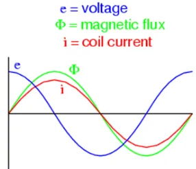
[image:2.612.355.509.135.275.2]The main causes of transient inrush current are as moment of switching, residual flux. Transformer is highly inductive in nature. Thus current lags voltage by 90° as shown in fig.1.
Fig. 1. Transformer energization when voltage is at 0°
As shown in fig. 2, when transformer energized at 0 drgree the value of flux and current are at negative peak.Thus the flux are increases at the higher rate and it becomes twice the value of flux in steady state condition.this higher value leads to increasing the current ten to fifteen times the rated value.
Fig. 2.Transformer energization when voltage is at peak
[image:2.612.81.228.200.364.2]As fig.2 when the transformer are energized at its positive peak value of instanteneous voltage i.e at 90° at this instant the value of current and flux are zero. In order for the transformer to create an opposing voltage drop to balance against this applied source voltage, a magnetic flux of rapidly increasing value must be generated. The result is that winding current increases rapidly, but actually no more rapidly than under normal conditions.
Fig 3: Inrush current
Thus no any surge value of current is formed when primary of transformer is energized at peak value of instantaneous voltage
IV. EFFECTS OF INRUSH CURRENT
The inrush current affects whole power system. It mainly affects on transformer, protection system, equipments connected to system and raises power quality issues [7] [4] [2].
A.Transformer
As the inrush current increases the temperature increases by the theory of effect of negative temperature. So the temperature of bushings and the windings increases [7].
B.Protection system
In protection system relay is important equipment. It senses the short circuit or abnormal conditions of system to isolate and protect the system. The short circuit of transformer is always less than inrush current [4]. It is hence sensed by relay system, such that transformer is isolated from system which is unexpected. Thus inrush current causes malfunction of protective system. As transformer gets isolated due to effect on protection system there is interruption of system. [1].
C.Power quality
The presence of harmonic content in inrush current causes wrong analysis with medical equipments. It also affects to heat rise of the system [1].
V. ANALYSIS OF INRUSH CURRENT IN MATLAB/
SIMULINK
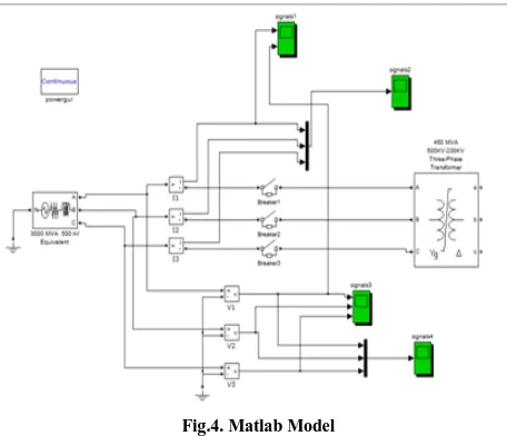
Matlab is user friendly software with simpower system toolbox. A test is driven on 450 kVA, 500kV/230kV
grounded Y/D transformer in MATLAB/SIMLINK
[image:2.612.73.216.455.578.2]International Journal of Emerging Technology and Advanced Engineering
Website: www.ijetae.com (ISSN 2250-2459,ISO 9001:2008 Certified Journal, Volume 4, Issue 2, February 2014)
[image:3.612.52.280.174.370.2]841 Analysis is done on inrush current of three phase transformer as shown in fig. 4. The switching time for circuit breaker is changed from its parameter settings.
Fig.4. Matlab Model
The switching time of circuit breaker is changed from 0° to 30°, 60° and 90° and various results are observed and analyzed. The calculations for switching angle are given as below-
Time duration for 50 cycles = 1000 msec 1 cycle =1000/50 = 20 msec
For switching at peak of voltage waveform with phase A, B and C 90° apart-
Phase A peak is at 90°=0.005 sec Phase B peak is at 90+120= 210°=0.0116 Phase C peak is at 90 +240 = 330°=0.01833
VI. RESULT ANALYSIS AND DISCUSSIONS
Fig. shows the inrush current drawn by transformer without point on wave switching
Time
C
u
r
r
e
n
[image:3.612.345.539.488.633.2]t
Fig.5: Current waveform at at 0° for R phase
Time
V
o
l
t
a
g
e
Fig 6: Voltage waveform at 0° degree for R phase
Time
C
u
r
r
e
n
t
Fig 7: Current waveform at 90° degree for R phase
Time
V
o
l
t
a
g
e
[image:3.612.59.277.563.702.2]International Journal of Emerging Technology and Advanced Engineering
Website: www.ijetae.com (ISSN 2250-2459,ISO 9001:2008 Certified Journal, Volume 4, Issue 2, February 2014)
[image:4.612.324.573.129.324.2]842
Table I
Magnitude value of current and voltage Switching Angle Imagnitude Vmag
0° 1800 3.1*105
30° 2000 3.6*105
60° 1500 4*105
90° 820 4*105
Table I explains the magnitude values of current and voltage at different switching angle. It shows that the value of current at 0° is too high and when the switching are provided at 90° by using point on wave switching method current value get reduced to lower value
.
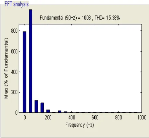
[image:4.612.80.256.155.265.2]Fig 9: THD analysis for current of R phase at 0°
[image:4.612.49.293.336.562.2]Fig 10: THD analysis for voltage of R phase at 0°
[image:4.612.327.574.348.552.2]International Journal of Emerging Technology and Advanced Engineering
Website: www.ijetae.com (ISSN 2250-2459,ISO 9001:2008 Certified Journal, Volume 4, Issue 2, February 2014)
[image:5.612.68.442.125.675.2]843
[image:5.612.338.550.148.593.2]Fig.12. THD analysis for voltage of R phase at 90° Table II
Second Harmonic at 0°
S/W phase I(H2%)
0°
A 11.74
B 31.74
C 34.92
Table III Second Harmonic at 30°
S/W Phase I(H2%)
30°
A 22.66
B 52.20
C 74.93
Table IV Second Harmonic at 60°
S/W Phase I(H2%)
60°
A 38.20
B 87.59
C 85.65
Table V Second Harmonic at 90°
S/W Phase I(H2%)
90°
A 64.98
B 101.30
C 99.47
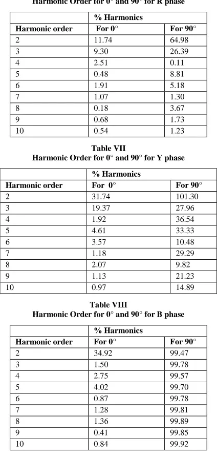
Tables II-V explains the value of second harmonic component for three phases at different switching angles.
Table VI
Harmonic Order for 0° and 90° for R phase % Harmonics
Harmonic order For 0° For 90°
2 11.74 64.98
3 9.30 26.39
4 2.51 0.11
5 0.48 8.81
6 1.91 5.18
7 1.07 1.30
8 0.18 3.67
9 0.68 1.73
10 0.54 1.23
Table VII
Harmonic Order for 0° and 90° for Y phase % Harmonics
Harmonic order For 0° For 90°
2 31.74 101.30
3 19.37 27.96
4 1.92 36.54
5 4.61 33.33
6 3.57 10.48
7 1.18 29.29
8 2.07 9.82
9 1.13 21.23
10 0.97 14.89
Table VIII
Harmonic Order for 0° and 90° for B phase % Harmonics
Harmonic order For 0° For 90°
2 34.92 99.47
3 1.50 99.78
4 2.75 99.57
5 4.02 99.70
6 0.87 99.78
7 1.28 99.81
8 1.36 99.89
9 0.41 99.85
10 0.84 99.92
In above table the harmonic order is given in which second harmonic value is more
.
VII. CONCLUSION
[image:5.612.50.299.154.525.2] [image:5.612.79.258.383.686.2]International Journal of Emerging Technology and Advanced Engineering
Website: www.ijetae.com (ISSN 2250-2459,ISO 9001:2008 Certified Journal, Volume 4, Issue 2, February 2014)
844 In all conditions the second order harmonics component found upper magnitude as compared to others, thus the second order harmonics restraining protective system can be designed in order to minimize hazards to protective system.
REFERENCES
[1] F.Fard Ali Asghar, K.P.Basu, ―Reduction of three phase transformer
magnetizing inrush current by use of point on wave switching method‖, Proceedings of 2009 IEEE student conference on research development, 2009
[2] M.Jamali, M. Mirzaie, ―Calculation & Analysis of transformer
inrush current based on parameters of transformer & operating conditions‖, IEEE, 2011K.
[3] Sagar Bole, ―Mitigation of inrush current in transformer‖ IJITEE, Dec 2013.
[4] Ramsis Girgis, Z. Gajic, ―Power transformer characteristics & their
effects on protective relays‖, 33rd Western protective relay
conference, 17 Oct 2006.
[5] H. John, J. Klaus, ―Elimination of transformer inrush current by
controlled switching-part 1st: Theoretical considerations‖, IEEE
Transactions on power delivery, April 2001.
[6] S. Ramsis, ―Characteristics of inrush current of present design of power transformer‖, IEEE, April 2010.
[7] Michael steurer, Klaus Frohlich, ―The impact of inrush current on the mechanical stress of high voltage power transformer coil‖, IEEE Transactions on power delivery, January 2002.
[8] Yu Cui, G. Sami, ―A sequential phase Energization technique for transformer inrush current reduction- part 1st: simulation &
experimental results‖, IEEE Transactions on power delivery, 2 April 2005
[9] J. F. Holcomb, Distribution transformer magnetizing inrush current,