International Journal of Emerging Technology and Advanced Engineering
Website: www.ijetae.com (ISSN 2250-2459,ISO 9001:2008 Certified Journal, Volume 4, Issue 12, December 2014)
140
Numerical
Analysis of Excavation Backfilled with Soil-Based
Controlled Low-Strength Materials: Part II- Steady-State
Elasto-Dynamic Analysis
Huang Li-Jeng
1, Sheen Yeong-Nain
2, Hsiao Darn-Horng
3, Le Duc-Hien
41Associate Professor, 2Professor, 3Associate Professor, 4Ph.D. Candidate, Department of Civil Engineering, National
Kaohsiung University of Applied Science, 80778, Taiwan, Republic of China
Abstract—This paper presents the steady-steady elasto-dynamic analysis of excavation backfilled with sustainable material, a controlled low-strength material (CLSM), using finite element (FE) and boundary element (BE) methods. The CLSM is backfilled after a retaining wall under the pavement of a road. The Young’s moduli of CLSM are obtained from laboratory tests for different ages including 1, 7, 28 days and two different binder mixtures. Two-dimensional planar strain is employed in the FE and BE formulation of elasto-dynamic analyses. Typical examples will be employed for comparison study of backfill material using CLSM and sandy soil or concrete. Emphasis is put on the natural frequencies and mode shapes of the excavation backfilled with CLSM at different ages, with different binder mixtures and compared with different materials. Programs will be coded in MATLAB, convergence studies will be completely assured and the numerical results will be checked by FE and BE. Results are expected to assure the applicability and advantages of CLSM as a suitable sustainable material employed for excavation backfilling in highway and geotechnical engineering.
Keywords—Boundary element method (BEM), Controlled low-strength material (CLSM), Elasto-dynamic analysis, Excavation backfill, Finite element method (FEM).
I. INTRODUCTION
Recently, sustainable materials have been widely studied and developed especially for construction, highway and civil engineering. Controlled low-strength material (CLSM) is commonly used as backfilled materials. It would be a friendly environment-cheap material and typically consists of small amount cement, supplementary, fine aggregates, and a large amount of mixing water. Self-compacting/ -leveling, significantly low strength, as well as almost no measured settlement after hardening are remarkable characteristics of CLSM [1]. Recent studies have reported that maximum CLSM strength of approximately up to 1.4 MPa is suitable for most of backfilling applications when re-excavation is required [2,3]
It is also recommended that depending upon availability and project requirements, any recycle materials would be acceptable in production of CLSM with prior tests its feasibility before uses [1]. Literature reviews showed that on-site residual soil after pipeline excavation may be an alternative source for fine constituent in production of soil-based CLSM, effectively used as backfill around buried pipelines [3, 4]. Schmitz et al. have conducted experimental and computational works on the use of CLSM as abutment backfill [5]. The authors also conducted some preliminary studies on engineering properties of CLSM [6-8] and static deformation and stress analysis of backfilled zone using CLSM [9].
Some of reasons that cause failure of retaining wall are due to (1) increase of lateral earth pressure behind the wall, (2) reduction of water pressure at the front of the wall, and (3) liquefaction of the backfill material [10]. In order to assure the CLSM to be confident material for backfilling the static and dynamic mechanical behaviors should be clearly understood. Numerical analyses based on finite element methods (FEM) or boundary element methods (BEM) might become available and convenient tools. The static parts have been verified well [9] and this paper is aimed at the steady-state elasto-dynamic analysis of excavation backfilled with CLSM using finite element (FE) and boundary element (BE) methods based on elastic wave theory. The effects of backfilling materials on the natural frequencies are investigated in detail.
II. EXPERIMENTAL RESULTS
2.1 Materials used, and mix proportion
International Journal of Emerging Technology and Advanced Engineering
Website: www.ijetae.com (ISSN 2250-2459,ISO 9001:2008 Certified Journal, Volume 4, Issue 12, December 2014)
141
The soil was obtained from a construction site. The experimental work was conducted on two binder content levels in mixtures (i.e. 80- and 130 kg/m3). The water-to-binder ratio was selected via few trial mixes until the acceptable flow-ability for CLSM of 150300 mm were achieved. The detailed can be referred in [8].
2.2 Testing results
(a) Stress-strain behavior and modulus of elasticity at different ages
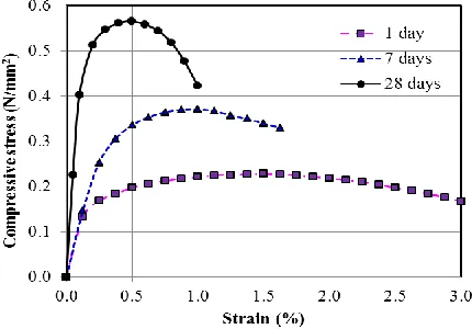
An axial load from a low-capacity hydraulic machine (100 kN) was slowly and uniformly applied to the capping specimens until failure at a constant displacement rate of 0.51 mm/min. The strain after each loading increment was measured by reading on two dial gages, graduated in 0.01 mm. It can be observed that the longer ages the higher UCS was obtained along with a drastic change in shape of stress-strain curve, as typically shown in Fig. 1. The results imply that at early ages, CLSM behaves as a soil material with more ductile characteristic, but with long-term ages the material acts more like concrete, with higher strength and lesser strain (brittleness).
Figure 1. Stressstrain response for Mix-1 at 1-, 7-, and 28 days.
(b) Modulus of elasticity of different mixtures
[image:2.612.332.557.229.397.2]The elastic modulus was calculated as the slope of the secant line drawn from the origin to a point on the stress-strain curve at 40% peak stress. The values of 28-day elastic moduli of all CLSM mixtures were displayed in Fig. 2. The B80 and B130 denote for mixture series containing 80 and 130 kg/m3, respectively.
Figure 2. 28-days Elastic moduli of CLSM with different mixtures
III. NUMERICAL ANALYSIS OF BACKFILLED ZONE
3.1 Problem description
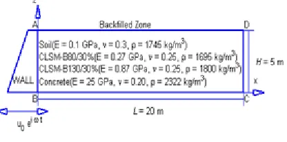
A backfilled zone with length L20m , height
m
[image:2.612.59.274.404.554.2]International Journal of Emerging Technology and Advanced Engineering
Website: www.ijetae.com (ISSN 2250-2459,ISO 9001:2008 Certified Journal, Volume 4, Issue 12, December 2014)
142
TABLEI
DYNAMIC PROPERTIES OF DIFFERENT BACKFILL MATERIALS
Dynamic Properties
E (GPa)
(kg/m3)
G() (GPa)
(GPa)
2
1
c
(Vc) (m/s)
2
c
(Vs) (m/s)
Soil 0.10 0.3 1745 0.0385 0.0577 277.75 148.46
CLSM(1 Day) 0.12 0.25 2017* 0.048 0.048 267.20 154.27
CLSM(7 Days) 0.14 0.25 1899* 0.056 0.056 297.44 171.72
CLSM(28 Days) 0.47 0.25 1678* 0.188 0.188 579.75 334.72
CLSM(B80/30%) 0.27 0.25 1695* 0.108 0.108 437.21 252.42
CLSM(B130/30%) 0.87 0.25 1800* 0.348 0.348 761.58 439.70
Concrete 25 0.2 2322 10.4167 6.9444 3458.74 2118.04
* air-dried
Data collected from Ref: [5] and [8]
In dynamic analysis, three material properties, Young’s modulus (or Shear modulus), Poisson’s ratio and density, affect the characteristics of the backfilled zone [10]. To simulate the steady-state elasto-dynamic response of the backfilled zone subjected to cyclic ground motion caused from the rigid retaining wall, we consider boundary conditions to be:
(a) on AB: u(0,z)u0eit
(b) on BC: v(x,0)0
(c) on CD: u(20,z)0
(d) on DA: tx(x,5)ty(x,5)0
[image:3.612.85.523.157.297.2]Where u00.01m is the presumed amplitude of displacement of exciting retaining wall induced by cyclic earthquake motion with exciting frequency
Figure 3 Problem description
3.2 Basic assumptions
The basic assumptions of numerical analysis are:
(1) Retaining wall is perfectly rigid;
(2) Backfilled zone is homogeneous ad isotropic and is in the state of plane strain;
(3) Displacements perpendicular to the bottom and right-hand side boundaries of backfilled zone are fixed. (4) Horizontal displacement of the left-hand side
boundaries of backfilled zone is the same as the rigid retaining wall.
3.3 Finite element formulation
We can deduce the general finite element equations of equilibrium in the matrix form as [11]:
} { } ]{ [ } ]{
[M x K x f (1)
Where [M],[K]denotes the global inertia and stiffness matrix, {x} and {f}denotes the nodal degrees of freedom ad nodal loads of the finite element system.
When free vibration is considered, we have the eigen-value problem:
} 0 { } ]){ [ ] [ 2
( M K X (2)
from that the natural frequencies n and mode shapes
n X}
{ can be obtained.
3.4 Boundary element formulation
[image:3.612.68.276.551.654.2]International Journal of Emerging Technology and Advanced Engineering
Website: www.ijetae.com (ISSN 2250-2459,ISO 9001:2008 Certified Journal, Volume 4, Issue 12, December 2014)
143
HijUjd GijUjd GijBjd j
U ij
c ˆ ˆ ˆ ˆ (3)
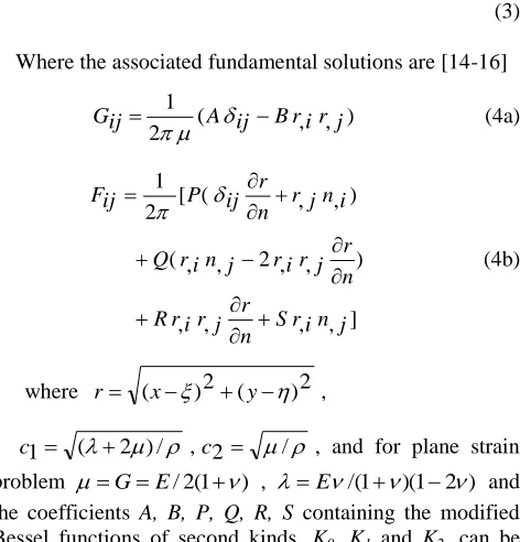
Where the associated fundamental solutions are [14-16]
) , , ( 2 1 j r i r B ij A ij
G
(4a)
] , , , , ) , , 2 , , ( ) , , ( [ 2 1 j n i r S n r j r i r R n r j r i r j n i r Q i n j r n r ij P ij F (4b)
where r (x)2(y)2 ,
2 )/
( 1
c ,c2 / , and for plane strain problem GE/2(1) , E/(1)(12) and the coefficients A, B, P, Q, R, S containing the modified Bessel functions of second kinds, K0, K1 and K2, can be
referred to Ref. [13-16].
Discretization of the boundary integrals and domain leads to the matrix equation:
} ˆ )]{ ( [ } ˆ )]{ ( [ } ˆ )]{ (
[H s U G s P C s B (5)
in which [H(s)],[G(s)] denotes the influence matrices corresponding to the displacement and traction vectors,
} ˆ
{U and {Pˆ}, respectively.
For steady-state elaso-dynamic analysis, we can set
i
s in Eq. (3) and solve out the displacements or tractions and determine the eigen-values (natural frequencies) n and eigen-vectors (natural modes) {Uˆ}n.
It should be noticed that in the BE, the influence matrices contain the frequency and thus eigen-values should be evaluated by scanning and searching scheme and the computation time increase significantly rather than using the finite element method.
IV. NUMERICAL RESULTS AND DISCUSSION
4.1 FE and BE meshes for the problem
Various FE and BE meshes have been tested, e.g. 100 Constant Strain Rectangular (CSR) FEs, 200 Constant Strain Triangular (CST) FEs, and 50, 100, 200 constant BEs (Fig. 4-7).
[image:4.612.52.288.157.403.2]All the programs are coded in MATLAB. Using boundary-type numerical solutions such as BE is easy for data preparation.
Figure 4. 200 constant strain triangular (CST) finite element mesh
Figure 5. 50 constant boundary element mesh
International Journal of Emerging Technology and Advanced Engineering
Website: www.ijetae.com (ISSN 2250-2459,ISO 9001:2008 Certified Journal, Volume 4, Issue 12, December 2014)
144
Figure 7. 200 constant boundary element mesh4.2 Convergence tests
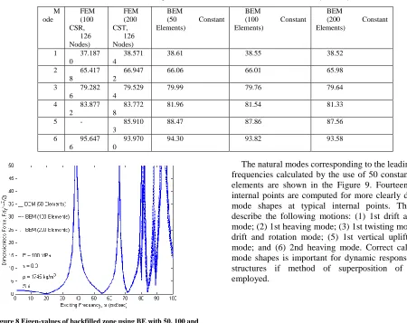
Table II shows the numerical prediction of natural frequencies of backfilled soil calculated using BE meshes and FE meshes. Convergent results can be obtained using 50, 100 and 200 boundary elements and agree well with FE results. Figure 8 shows the calculated dimensionless amplitude of total force exerted on retaining wall versus exciting frequency using three BE meshes. Resonance and peak occurs when the exciting frequency coincides with the natural frequency and can be well predicted by three BE meshes. It can be observed that usage of only 50 boundary elements can predict natural frequencies well, especially for the important leading modes.
TABLEII
COMPUTED NATURAL FREQUENCIES OF EXCAVATION BACKFILLED WITH SOIL (RAD/SEC)
M ode
FEM (100 CSR,
126 Nodes)
FEM (200 CST,
126 Nodes)
BEM
(50 Constant Elements)
BEM
(100 Constant Elements)
BEM
(200 Constant Elements)
1 37.187 0
38.571 4
38.61 38.55 38.52
2 65.417 8
66.947 2
66.06 66.01 65.98
3 79.282 6
79.529 4
79.99 79.76 79.64
4 83.877 2
83.772 8
81.96 81.54 81.33
5 - 85.910
3
88.47 87.86 87.56
6 95.647 6
93.970 0
[image:5.612.68.518.335.692.2]94.30 93.82 93.58
Figure 8 Eigen-values of backfilled zone using BE with 50, 100 and 200 constant elements
International Journal of Emerging Technology and Advanced Engineering
Website: www.ijetae.com (ISSN 2250-2459,ISO 9001:2008 Certified Journal, Volume 4, Issue 12, December 2014)
145
Figure 9 Mode shapes of the first six natural modes of the backfilledsoil
[image:6.612.94.250.154.291.2]4.3 Comparison study of CLSM backfilled materials at three different ages
Table III shows computed one-day CLSM has nearly the same fundamental frequencies as that of soil while when the ages increase from 7-days to 28-days the natural frequencies increase significantly. After 28 days the CLSM can reach over two times of the natural frequencies of 1-day CLSM and soil.
TABLEIII
COMPUTED NATURAL FREQUENCIES OF CLSM AT DIFFERENT AGES (RAD/SEC)
Materil s
Soil CLSM (1
Day)
CLSM (7 Days)
CLSM (28 Days)
Concrete
Mode FEM BEM F EM B EM FE M B EM FE M BE M FE M BE M
1 38.5
7 38.6 1 3 9.05 3 9.13 43. 47 43. 56 84. 74 84. 91 522. 33 520. 72
2 66.9
5 66.0 6 6 9.35 6
8.62 77.20 76. 39
15 0.48
14
8.90 949.97 947. 28
3 79.5
3 79.9 9 7 8.09 8
0.30 86.93 89. 39 16 9.44 17 4.23 102 1.56 102 0.93
4 83.7
7 81.9 6 8 2.90 8
2.61 92.28 91. 96 17 9.86 17 9.25 107 5.05 107 1.63
5 85.9
1 88.4 7 8 5.73 8
4.98 95.44 94. 60 18 6.02 18 4.39 115 7.99 115 7.65
6 93.9
7 94.3 0 9 0.50 9 1.13 10 0.75 10 1.45 19 6.37 19 7.74 116 7.08 117 3.78
4.4 Comparison study of CLSM backfilled materials with two different binder mixtures
Table IV depicts that computed natural frequencies of B130/30% are higher than those of B80/30% and both are higher than those of soil.
[image:6.612.126.489.345.508.2]International Journal of Emerging Technology and Advanced Engineering
Website: www.ijetae.com (ISSN 2250-2459,ISO 9001:2008 Certified Journal, Volume 4, Issue 12, December 2014)
146
TABLEIV
COMPUTED NATURAL FREQUENCIES OF CLSM WITH DIFFERENT MIXTURES (RAD/SEC)
Mat erils
Soil CLSM
(B80/30%) CLSM (B130/30%) Concrete Mo de F EM B EM FE M BE M FE M BE M FE M BE M
1 3
8.57 3 8.61 63. 90 64. 03 111. 31 111. 54 522. 33 520. 72
2 6
6.95 6 6.06 113 .48 112 .29 197. 67 195.
59 949.97 947. 28
3 7
9.53 7 9.99 127 .78 131 .39 222. 58 228. 87 102 1.56 102 0.93
4 8
3.77 8 1.96 135 .64 135 .18 236. 27 235. 47 107 5.05 107 1.63
5 8
5.91 8 8.47 140 .28 139 .05 244. 36 242. 21 115 7.99 115 7.65
6 9
[image:7.612.149.465.157.313.2]3.97 9 4.30 148 .09 149 .12 257. 96 259. 76 116 7.08 117 3.78
Figure 10 Mode shapes of the first six natural modes of the backfilled CLSM-B80/30%
Figure 11 Mode shapes of the first six natural modes of the backfilled CLSM-B130/30%
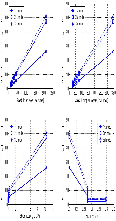
4.5 Effect on natural frequencies of design parameters
In order to understand effect on natural frequencies of the design parameters, we plot the first leading three natural frequencies of the backfilled zone with some parameters of different materials discussed previously, including speed of shear wave, Vs; speed of compressive wave, Vc; shear modulus, G; and Poisson’s ratio, ; the results are shown in Figure 12. It can be observed that:
(1) natural frequencies of backfilled zone with different materials seems to be linearly proportional to the speed of shear wave (Vs) and compressive wave (Vc), respectively. The wave speeds of each CLSM lie between those of soil and concrete and are more close to the soil than concrete. If we add more binder mixtures and increase wave speeds we can expect to increase fundamental frequencies too.
(2) natural frequencies of backfilled zone with different materials are proportional to the square root of shear modulus (G) , (and the Young’s modulus (E) too, not shown here.). This is reasonable because the speeds of waves (Vs, Vc) are square root of shear modulus (G) which is linearly related to Young’s modulus (E). (3) Concerning about the effect of Poisson’s ratio () on
[image:7.612.94.254.340.480.2] [image:7.612.93.255.538.670.2]International Journal of Emerging Technology and Advanced Engineering
Website: www.ijetae.com (ISSN 2250-2459,ISO 9001:2008 Certified Journal, Volume 4, Issue 12, December 2014)
147
[image:8.612.71.264.252.618.2]It is noticed that density of backfilled materials is also an important design parameter. However, the density (or unit weight) of CLSM varies with time and the content of water. From the theory of wave propagation in elastic media, the wave speeds Vs and Vc are inversely proportional to the square root of density. If other parameters are fixed, we also can control and design the density of backfilled material.
Figure 12 Variation of the first three natural frequencies of backfilled zone with design parameters
V. CONCLUDING REMARKS
Numerical calculation of natural frequencies of backfilled zone based on theory of elasto-dynamics show that both finite element and boundary element method can provide satisfactory results; however, FEM is more convenient for calculation of all natural frequencies and BEM has the advantage of easy data preparation as well as mode shape prediction. In addition, numerical test studies show that:
(a) natural frequencies of CLSMs lie between those of soil and concrete and in general for each mode the value is higher than that of soil. This reveals that CLSM is a good backfilling material since increase of fundamental frequencies can help to avoid low-frequency resonance resulting from seismic excitation, moving vehicles or oscillatory machines. Furthermore, mode shapes for CLSMs are similar to the soil and concrete even though the corresponding frequencies are different.
(b) natural frequencies of backfilled zone of different materials seems to be linearly proportional to the speed of shear wave (Vs) and compressive wave (Vc), and are proportional to the square root of shear modulus (G) but inversely to the Poisson’s ratio. In the design of CLSM, the target can be set to increase shear modulus (or Young’s modulus), reduce Poisson’s ratio, and lessen density of material.
(c) Consideration of dynamic characteristics of excavation
backfilled with CLSM,
CLSM(B130/30%)( E0.87GPa, 0.25, 3
/
1800kg m
) shows to be a good selection for backfilling material.
Acknowledgements
The authors would like to thank the National Science Council of the Republic of China, Taiwan, for financially supporting this research under the Contract No. MOST 103-2221-E-151-046.
REFERENCES
[1] ACI-229R, 2005. Controlled-low strength materials (Reproved 2005), Farmington Hills (MI).
International Journal of Emerging Technology and Advanced Engineering
Website: www.ijetae.com (ISSN 2250-2459,ISO 9001:2008 Certified Journal, Volume 4, Issue 12, December 2014)
148
[3] Finney, A. J., Shorey, E. F. and Anderson, J. 2008.Use of native soil in place of aggregate in controlled low strength material (CLSM), International Pipelines Conference 2008, Atlanta, Georgia, United States, 1-13.
[4] Howard, A., Gaughan, M., Hattan, S. and Wilkerson, M. 2012. Lean, Green, and Mean: The IPL Project. ICSDEC 2012: American Society of Civil Engineers, 359-366.
[5] Schmitz, M. E., Parsons, R. L., Ramirez, G. and Zhao, Y. 2004. Use of controlled low-strength material as abutment backfill, Technical Report K-TRAN: KU-02-6, The Kansas Department of Transportation, Topeka, Kansas, University of Kansas, U.S.A. [6] Sheen, Y. N., Huang, L. J., and Le D. H., 2014. Engineering
properties of controlled low-strength material made with residual soil and Class F fly ash, 3rd International Conference for Advanced Materials Design and Mechanics and Workshop on Android Robotics, Paper No. 54, Singapore, May 23-24.
[7] Huang, L. J., Sheen, Y. N. and Le, D. H., 2014. On the multiple linear regression and artificial neural networks for strength prediction of soil-based controlled low-strength material, 3rd International Conference for Advanced Materials Design and Mechanics and Workshop on Android Robotics, Paper No. 55, Singapore, May 23-24..
[8] Sheen, Y. N., Hsiao, D. H., Huang, L. J. and Le, D. H.,2014. Stress-strain behavior of soil-based controlled low-strength material, the International Conference on Green Technology for Sustainable Development 2014, Ho Chi Minh, Viet Nam, October 30 - 31.
[9] Huang, L. J., Sheen, Y. N., Hsiao, D.H. and Le, D. H., 2014. Quasi-steady analysis of excavation backfilled with soil-based controlled low-strength material using finite element and boundary element methods, the International Conference on Green Technology for Sustainable Development 2014, Ho Chi Minh, Viet Nam, October 30 - 31.
[10] Das, B. M. and Ramana, G. V., 2011. Principles of Soil Dynamics, 2nd edition, Cengage Learning.
[11] Rao, S. S., 1982. The Finite Element Method in Engineering, Pergamon Press..
[12] Brebbia, C. A., Telles, J.C.F.. and Wrobel, L. C., 1984. Boundary Element Techniques, Springer-Verlag.
[13] Banerjee, P. K., 1994. The Boundary Element Methods in Engineering, McGraw-Hill.
[14] Cruse, T. A. and Rizzo, F. J., 1968. A direct formulation and numerical solution of the general transient elastrodynamic problem, I, J. Math. Anal. Appl., 22(1), 244-259.
[15] Cruse, T. A., 1968. A direct formulation and numerical solution of the general transient elastrodynamic problem, II, J. Math. Anal. Appl., 22(2), 341-355.