International Journal of Emerging Technology and Advanced Engineering
Website: www.ijetae.com (ISSN 2250-2459,ISO 9001:2008 Certified Journal, Volume 4, Issue 11, November 2014)
467
Analysis of Controllers for Speed Control in Brushless DC
Motor Using MATLAB
S. Iyappan
1, M. Vijayalakshmi
2, R. Ramaprabha
31PG Student, 2Research Scholar, 3Associate Professor, Department of Electrical and Electronics Engineering, SSN College of
Engineering, Chennai, Tamilnadu, India
Abstract— This paper presents a comparative analysis of
speed control in brushless DC motor (BLDC motor) using proportional-integral (PI) controller and Fuzzy logic controller (FLC). The controllers were analyzed under no load and loaded condition of the motor. The various parameters such as settling time, peak over shoot, steady state error, and mean square error were calculated and compared for both the controllers. A comparison graph has also been plotted between PI and FLC for speed response and observed that fuzzy controller offers better response in speed control while PI controller has good compliance over variation of load torque but has slow settling response. The entire model is simulated in MatLab-Simulink environment and the results were presented.
Keywords—BLDC motor, Fuzzy logic controller, PI controller, Speed control, MatLab
I. INTRODUCTION
Reliability and controllability are the two major factors for industrial based motors. These can be achieved through proper choice of controllers. In this paper, analysis is done to control the speed using PI controller and fuzzy logic controller. For comparison the motor, is first simulated under open loop condition and the dc link voltage is adjusted to obtain a base speed of 1000 rpm. The performance of the motor is analyzed under no load and loaded condition. For better understanding the motor is simulated under no load till 0.1s run time of simulation and at 0.1s the motor is loaded and observed. The output wave forms of the phase current, emf, torque, and speed were obtained and presented in the paper.
Industrial drives require acute speed control and hence closed loop system with current and speed controllers coupled with sensors are required. Thus this paper presents a detailed comparison of BLDC motor with PI controller and fuzzy logic controller. The various performance parameters of the motor are observed under no load and loaded condition. The results of these were tabulated and analyzed for both the controllers. Finally the performance comparison between the PI controller and fuzzy logic controller is done.
The graph is plotted with the speed response obtained from PI and fuzzy logic controller along with a reference speed of 1000rpm.
BLDC motors being non-linear in nature can easily be affected by the parameter variations and load disturbances [1]. Hence the proper choice of controller is gives a better performance by reducing the problem of overshoot, settling time, and fast response. Thus in this paper the various parameters such as time of settling, peak overshoot, mean square error and steady state error were observed in simulation and a comparative tabulation is presented [2].
The organization of the paper is as follows. Section 2 deals with the construction, working principle and operation. Section 3 deals with the design parameters of the motor and simulation results were discussed in Section 4. Finally the results were compared and presented.
II. OPERATIONAL BEHAVIOUR OF BLDC MOTOR
Similar to the other motors, BLDC motors also contains a rotor and a stator as in Fig-1. The stator is made up of laminated steel which can be stacked to carry the windings. The windings can be arranged either as star pattern (Y) or delta pattern (Δ). The Y pattern provides high torque at lower RPM and the Δ pattern provides low torque at low RPM, which in turn increases the losses and reduces the efficiency [2].
Fig-1: Stator and rotor of BLDC motor
International Journal of Emerging Technology and Advanced Engineering
Website: www.ijetae.com (ISSN 2250-2459,ISO 9001:2008 Certified Journal, Volume 4, Issue 11, November 2014)
468 The main disadvantage of a spotless core is higher cost because it requires more winding to compensate for the larger air gap. The rotor shown in Fig-1 is made out of permanent magnets. Depending upon the application requirements, the number of poles in the rotor will vary. Increased number of poles gives a better torque and reduced maximum possible speed.
Fig-2: Slotted and slotless stator core
The working principle of the BLDC motor is as same as that of the brushed DC motor. In brushed DC motor, feedback is implemented using a mechanical commutator and brushes. But in BLDC motor, feedback sensors such as optical encoders and hall sensors are used. The position of the shaft can be determined by observing the sensor signals which may be high or low depending on the rotor magnetic poles. Based on the position of the motor identified using feedback sensors –two of the three electrical windings are energized at a time which is depends on which commutation we used may be a 120° or 180° commutation. The corresponding commutation table and sequence is shown in Fig-3 that determines which motor phase winding to be switched ON [3]-[4].
Fig-3: Commutation table and sequence
III. DESIGN AND MODELLING OF BLDCMOTOR
The machine is represented with a series resistance (Rs),
inductance (Ls) and back EMF (es ) [5].
The equivalent circuit is shown in Fig-4 and from this the line voltages Van, Vbn, Vcn for each phase is written as,
a e ic ca L ib ba L ia aa L dt d a i a R an
V ( )
(1) b e ic cb L ib bb L ia ab L dt d b i b R bn
V ( )
(2) c e ic cc L ib bc L ia ac L dt d c i c R cn
V ( )
(3)
It can assumed that
R c R b R a
R
(4) s L cc L bb L aa
L
(5) M cb L bc L ac L ca L ab L ba
L
(6)
c e b e a e c i b i a i dt d s L M M M s L M M M s L c i b i a i R R R cn V bn V an V 0 0 0 0 0 0(7) As 0 ib ic a
i &(Ls M)L
(8)
c e b e a e c i b i a i dt d s L s L s L c i b i a i R R R cn V bn V an V 0 0 0 0 0 0 0 0 0 0 0 0(9)
Where, R is Stator resistance per phase; Ls is Stator
inductance per phase; M is mutual inductance between the phases; ia,ib,ic is stator phase currents. The instantaneous
EMF equations can be given as follows:
m p r a f a
e ( )
(10) m p r b b
f
e
(
)
(11) m p r c c
f
e
(
)
(12)
Where, ωm is the rotor mechanical speed and θr is the
International Journal of Emerging Technology and Advanced Engineering
Website: www.ijetae.com (ISSN 2250-2459,ISO 9001:2008 Certified Journal, Volume 4, Issue 11, November 2014)
469 The torque equation is
]
)
(
)
(
)
(
[
a r a b r b c r cp
e
f
i
f
i
f
i
T
(13) Thus for a simple system,
m l m
e
T
B
dt
d
J
T
(14)
Where, J is the inertia and B is the frictional coefficient.
The relation between angular velocity and angular position (electrical) is given by (15).
m
r
p
dt
d
2
(15) [image:3.612.51.290.394.520.2]
Where, P is the number of rotor poles. An inverter is needed for supplying the voltage to the motor phase windings. The semiconductor switches in the inverter circuit are turned ON and OFF based on the hall signals obtained from the hall sensors which gives the rotor position as in Fig-4.
Fig-4: Inverter circuit for BLDC motor
The phase voltages of an inverter may be defined by the following
0
0 n
a
an
v
v
v
(16)
0
0 n
b
bn
v
v
v
(17)
0
0 n
c
cn
v
v
v
(18)
WhereVao, Vbo, Vco are three phase voltages and Vno is
the neutral voltage with respect to zero reference potential at the mid-point of dc link.
The hysteresis current controller can be used for limiting the stator current of BLDC motor within the limit chosen by the hysteresis band limit, which can switch ON/OFF the power switches. The switching patterns are follows:
If 𝑖𝑎𝑒𝑟𝑟>UL, S1 is on and S2 is off.
If 𝑖𝑎𝑒𝑟𝑟< LL, S1 is off and S2 is on.
If 𝑖𝑏𝑒𝑟𝑟>UL, S3 is on and S4 is off.
If 𝑖𝑏𝑒𝑟𝑟< LL, S3 is off and S4 is on.
If 𝑖𝑐𝑒𝑟𝑟>UL, S5 is on and S6 is off.
If 𝑖𝑐𝑒𝑟𝑟< LL, S5 is off and S6 is on.
Where, 𝑖𝑎𝑒=current error (𝑖𝑎ref. - 𝑖𝑎actual ); UL is Upper limit and LL is lower limit of hysteresis band. The magnitude of the reference current (I*) is determined by using reference torque (T*) and the back emf constant (Kb)
as (19).
b
K
T
I
* *
(19)
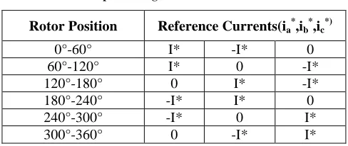
Depending on the rotor position, the values I*, -I* and zero for three-phase reference currents (ia *, ib *, ic *) are
generated and is listed in the Table-1.
Table -1:
Rotor position signal Vs reference current
Rotor Position Reference Currents(ia *
,ib *
,ic *)
0°-60° I* -I* 0
60°-120° I* 0 -I*
120°-180° 0 I* -I*
180°-240° -I* I* 0 240°-300° -I* 0 I* 300°-360° 0 -I* I*
Thus the equivalent circuit is obtained for which the method to obtain the reference currents is also discussed above. The speed control which is the main criteria is achieved by implementing proper controller. Here PI controller and fuzzy logic controller were discussed [6]-[7].
IV. CONTROLLERS FOR BLDCMOTOR
A. PI Controller
Conventional PI controller is used as a speed controller for recovering the actual motor speed to the reference. The Ziegler-Nichols method is used to determine the KPand Ki
[image:3.612.322.566.461.564.2]International Journal of Emerging Technology and Advanced Engineering
Website: www.ijetae.com (ISSN 2250-2459,ISO 9001:2008 Certified Journal, Volume 4, Issue 11, November 2014)
470
B. Fuzzy Logic Controller
It is a control algorithm based on linguistic control strategy which tries to account for controlling a system, similar to human knowledge. [6]-[8].
V. SIMULATION RESULTS
For analysis the motor is first simulated under open loop condition as in Fig-5 and the performance is observed. Then the simulation is done using PI controller and later with fuzzy logic controller under no load and loaded condition. The motor under open loop condition adjusts the speed by varying the dc link voltage. Simulated motor using PI controller varies KP and Ki and thereby the
required speed is obtained. The Kp and Ki values were
[image:4.612.326.552.108.703.2]found to be 0.9 and 77.14 respectively. Finally the motor with fuzzy logic controller is simulated [9] with seven triangular membership functions and therefore forty nine rules were used to obtain the required speed. The output waveforms such as phase current, torque, emf and speed were obtained and presented for all the above said cases. Based on the simulation waveforms a comparative graph on performance based on speed control and comparative table for motor under no load and loaded condition were presented. The motor parameters used for simulation purpose is shown in Table-2.
Table-2 Motor parameters
Motor Parameters Values
Input Voltage, Vdc 230 V
Stator phase resistance ( rs ) 2.68 Ω
Stator phase inductance (Ls) 5.31 mH
Pole pairs 4
Load Torque 1N-m
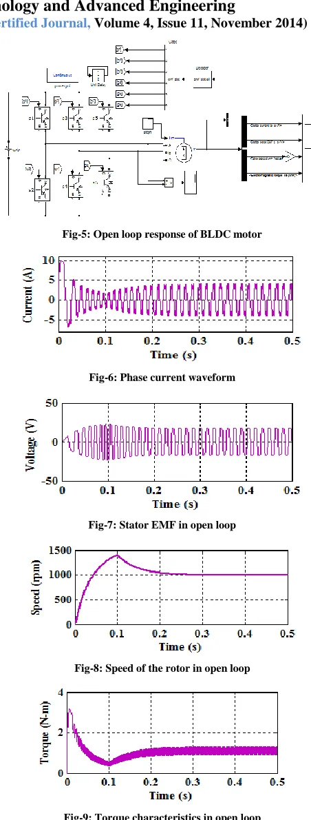
Fig-5 shows the MatLab-Simulink diagram of the conventional BLDC motor without any controller (open loop response) and the corresponding current, emf, speed and torque characteristics are shown in Fig-6 to Fig-9.
Fig-5: Open loop response of BLDC motor
Fig-6: Phase current waveform
Fig-7: Stator EMF in open loop
Fig-8: Speed of the rotor in open loop
[image:4.612.62.274.445.554.2]International Journal of Emerging Technology and Advanced Engineering
Website: www.ijetae.com (ISSN 2250-2459,ISO 9001:2008 Certified Journal, Volume 4, Issue 11, November 2014)
471
A. Response with PI Controller
Fig-10 shows the Simulink diagram of the BLDC motor without any controller and the corresponding back emf, current, speed and torque characteristics are shown from Fig- 11 to Fig-14.
Fig-10: PI controller for BLDC Motor speed control
Fig- 11: Phase current waveform with PI controller
Fig-12: Stator EMF with PI controller
Fig-13: Speed of the rotor with PI controller
Fig-14: Torque characteristics with PI controller
B. Response with FLC
Fig-15 shows the Simulink diagram of the BLDC motor with fuzzy logic controller and the corresponding backemf, current, speed and torque were also observed and presented vide Fig- 16 to Fig-19.
Fig-15: Fuzzy controller for BLDC Motor Speed control
Fig-16: Phase current waveform with FLC
International Journal of Emerging Technology and Advanced Engineering
Website: www.ijetae.com (ISSN 2250-2459,ISO 9001:2008 Certified Journal, Volume 4, Issue 11, November 2014)
472 Fig-18: Speed of the rotor with FLC
Fig-19: Torque characteristics with PI controller
VI. PERFORMANCE COMPARISON OF PI AND FUZZY
CONTROLLER
Referring to the above all simulation results, a comparison has been made and a graph has been plotted and presented in Fig- 20
Fig-20: Performance comparison between PI and FLC
The graph clearly states that fuzzy logic controller gives a better speed regulation than PI controller. Then a detail analyses was done by simulating the motor under no-load and loaded condition and hence the time of settling, peak over shoot, mean square error and steady state error were calculated and compared.
The results are presented for no load and loaded conditions in Table-3 and Table-4 respectively.
Table-3: Parameters at no-load
Controller
Settling time, ts
(s)
Percentage over shoot
(%)
Steady State Error
(%)
Mean square
error (%)
PI
Controller 0.019 4.37 0.0011 0.0796
Fuzzy Logic controller
0.011 0 0.945 0.0173
Table-4:
Parameters at loaded condition
Controller
Settling time, ts
(s)
Percentage over shoot
(%)
Steady State Error
(%)
Mean square
error (%)
PI
Controller 0.022 3.86 0.0019 0.07645
Fuzzy Logic controller
0.012 0 0.15 0.017194
VII. CONCLUSION
In this paper the PI and fuzzy controller along with Hysteresis current controller of BLDC motor drive system is implemented and simulation results were illustrated using MATLAB/Simulink. Comparison of performance parameters such as rise time, steady state error, peak over shoot, recovery time were obtained using PI and Fuzzy logic controllers. It is found that the control concept with fuzzy logic controller outperforms the PI controller in most of the aspects. Simulation results of the two controllers have been presented. As a future scope the fuzzy controller used in this system can be upgraded to an adaptive neuro-fuzzy controller that has the combined advantages of both the neural networks and fuzzy logic along with FPGA.
REFERENCES
[1] P. Yedamale, Microchip Technology Inc., AN885, 2003,―Brushless DC (BLDC) motor fundamentals‖
International Journal of Emerging Technology and Advanced Engineering
Website: www.ijetae.com (ISSN 2250-2459,ISO 9001:2008 Certified Journal, Volume 4, Issue 11, November 2014)
473
[3] H. M. Cheshmehbeigi and E. Afjei, 2013 ―Design optimization of a homo-polar salient-pole brushless DC machine: Analysis, Simulation, and Experimental Tests‖,IEEE Transactions on Energy Conversion, Vol. 28, No. 2, pp. 289-297.
[4] C. Sheeba Joice, S. R. Paranjothi, and V. Jawahar Senthil Kumar, 2014 ―Digital control strategy for four quadrant operation of three phase BLDC motor with load variations‖ IEEE Transaction on Industrial Informatics, Vol.9, No. 2, pp. 974-982,
[5] Marcin Baszynski and Stanislaw Pirog, 2014 ―A novel speed measurement method for a high-speed BLDC motor based on the signals m the rotor position sensor‖,IEEE Transaction on Industrial Informatics, Vol.10, No. 1, pp. 84-91, February 2014.
[6] Muhammad Firdaus Zainal Abidin, Dahaman Ishak and Anwar Hasni Abu Hassan, 2o11, ―A comparative study of PI, fuzzy and hybrid PI fuzzy controller for speed control of brushless DC motor drive‖, International Conference on Computer Application and Industrial Electronics, 978-1-4577-2059-8/11, pp.189-194.
[7] R. Shanmugasundram, K. Muhammad Zakariah and N. Yadaiah, 2014 ―Implementation and performance analysis of digital controllers for brushless DC motor drives‖ IEEE/ASME Transactions on Mechatronics, Vol. 19, No. 1, pp. 213-224. [8] Robert Horvat and Karel Jezernik, 2014 ―An event-driven approach
to the current control of a BLDC motor using FPGA‖,IEEE Transactions on Industrial Electronics, Vol. 61, No. 7, pp.3719- 3726.