International Journal of Emerging Technology and Advanced Engineering
Website: www.ijetae.com (ISSN 2250-2459,ISO 9001:2008 Certified Journal, Volume 3, Issue 9, September 2013)
376
Power Quality Improvement in A Smart Grid Using MPFC
K. Veerasekhar
1, N. Narasimhulu
2, P. Malleswara reddy
31PG Student, Dept. of Electrical and Electronics, S.K.D.E.C, Gooty, India
2Associate Professor, 3Assistant Professor, Dept. of Electrical and Electronics, S.K.D.E.C, Gooty, India
Abstract— This paper presents a new idea for smart electric grid stabilization and to improve the power quality for efficient utilization of electric power using modulated power filter compensator (MPFC). A tri – loop error driven inter coupled PID controller is used to adjust the PWM switching for MPFC. This paper also presents a Digital validation for different cases of loads and fault conditions without & with MPFC scheme for power quality enhancement, power factor correction, voltage stabilization and transmission line lose
reduction.
Keywords— MPFC, PID controller, Smart grid, Power Quality, voltage stabilization.
I. INTRODUCTION
In a modern electrical distribution system, there will be a sudden increase of nonlinear loads, such as power supplies, rectifier equipment used in telecommunication networks, domestic appliances, adjustable speed drives, etc. These power-electronic-based loads offer highly nonlinear characteristics. Due to their non-linearity characteristics power quality problems will arise i.e variation in voltage, current & frequency that may lead to equipment failure or malfunction [1].
The different technical options available to improve power quality, active power filters have proved to be an important alternative to compensate for current and voltage disturbances in power distribution systems [3], [4], [5] Different active power filters topologies have been presented in the technical literature, [8] [9] and many of them are already available in the market [2], [8]. Modern active filters are superior in filtering performance smaller in Physical size, and more flexible in application, compared to traditional passive filters [8], [9]. The shunt active filters are used for providing compensation of harmonics, reactive power and/or neutral current in ac networks, regulation of terminal voltage, suppression of the voltage flicker, and to improve voltage balance in three- phase system [10], [11]. Hybrid filters effectively mitigate the problems of both passive filters and pure active filter and provide cost effective and practical harmonic compensation approach, particularly for high power nonlinear loads.
The combination of low cost passive filters and control capability of small rating active filter effectively improve the compensation characteristics of passive filters and hence reduce the rating of the active filters, compared to pure shunt or series active filter solutions [12],[13]. Many power filter compensation configurations are proposed in literature to enhance power quality and to improve power factor [14]-[16].
The proposed scheme proved success in improving the power quality, enhancing power factor, reduce transmission losses and limit transient over voltage and inrush current conditions. The paper is organized in seven sections. Section II deals with the Modified power filter compensator. Section III Tri loop error driven modified PID controller with mat lab models. Ac study system is presented in Section IV. Section V presents the simulation results when different loads are applied, Section VI concludes the work.
II. MODULATED POWER FILTER COMPENSATOR (MPFC)
The low cost modulated dynamic series-shunt power filter and compensator is a switched type filter, used to provide measured filtering in addition to reactive
compensation. The modulated power filter and
compensator is controlled by the on-off timing sequence of the pulse width modulation (PWM) switching pulses that are generated by the dynamic tri loop error driven PID controller. The adaptive PID controller is equipped with a supplementary error-sequenced compensation loop for fast effective dynamic response in addition to the adaptive PID controller.
International Journal of Emerging Technology and Advanced Engineering
Website: www.ijetae.com (ISSN 2250-2459,ISO 9001:2008 Certified Journal, Volume 3, Issue 9, September 2013)
[image:2.612.64.285.134.338.2]377
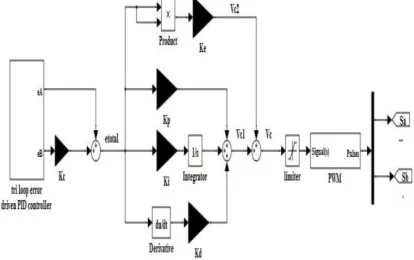
Fig.1: Modulated power filter compensator
III. TRI LOOP ERROR DRIVEN MODIFIED PIDCONTROLLER
[image:2.612.322.582.135.333.2]The tri-loop error-driven dynamic controller is a novel dual action control used to modulate the power filter compensator [17, 18]. The global error signal is an input to the modified PID controller to regulate the modulating control signal to the PWM switching block as shown in Figs. 2a & 2b. The modified PID includes an error sequential activation supplementary loop to ensure fast dynamic response and affective damping of large excursion, in addition to conventional PID structure.
Fig. 2.a:Modified tri loop error driven PID controller
Fig. 2.b:Mat lab functional model of the Inter-coupled tri loop error driven modified PID controller
IV. ACSTUDY SYSTEM
[image:2.612.328.577.482.651.2]The sample study AC grid network is shown in Fig.3. It comprises a synchronous generator (driven by steam turbine) delivers the power to a local hybrid load (linear, non-linear and induction motor load) and is connected to an infinite bus through 300 km transmission line. The system, compensator and controller parameters are given in the Appendix.
[image:2.612.65.272.491.621.2]International Journal of Emerging Technology and Advanced Engineering
Website: www.ijetae.com (ISSN 2250-2459,ISO 9001:2008 Certified Journal, Volume 3, Issue 9, September 2013)
378
V. SIMULATION RESULTS
The Matlab digital simulation results using
MATLAB/SIMULINK/Sim-Power Software Environment for the proposed MPFC scheme under three different study cases are: (A). Normal Loading Operating Case, (B). Short Circuit Fault Condition Case, (C). Hybrid Local Load Excursions Case
A. Normal Loading Operating Case:
The dynamic responses of voltage, current, reactive power and power factor at generator bus (Vg), load bus
(VL) and infinite bus (Vb) under normal operation are
shown from Figs. 4-15 The RMS values of voltage and current waveforms of the MPFC are shown in Fig. 16 and 17. The stable voltage signal of synchronous generator power system stabilization (PSS) is depicted in Fig. 18. The Transmission line losses are shown in Table I.
[image:3.612.331.533.152.229.2]
(a) (b)
Fig 4. RMS voltage (pu) at generator bus (a) without MPFC (b) with MPFC
(a) (b)
Fig 5. RMS voltage (pu) at load bus (a) without MPFC(b) with MPFC
(a) (b)
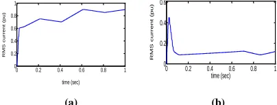
Fig 6. RMS current (pu) at generator bus (a) without MPFC (b) with MPFC
[image:3.612.332.553.171.613.2]
(a) (b)
Fig 7. RMS current (pu) at load bus (a) without MPFC (b) with MPFC
[image:3.612.58.281.350.437.2](a) (b)
Fig 8. Reactive power (pu) at generator bus (a) without MPFC (b) with MPFC
(a) (b)
Fig 9. Reactive power (pu) at load bus (a) without MPFC (b) with MPFC
0 0.2 0.4 0.6 0.8 1 0 0.2 0.4 0.6 time (sec) RM S cu r r e n t ( p u )
0 0.2 0.4 0.6 0.8 1
0 0.2 0.4 0.6 0.8 1 time (sec) RM S cu r r e n t ( p u )
0 0.2 0.4 0.6 0.8 1 0 0.5 1 1.5 time (sec) RM S vo lta g e ( p u )
0 0.2 0.4 0.6 0.8 1
0 0.5 1 1.5 time (sec) RM S V O L T A G E ( p u )
0 0.2 0.4 0.6 0.8 1 0 0.5 1 1.5 time (sec) RM S vo lta g e ( p u )
0 0.2 0.4 0.6 0.8 1
0 0.5 1 1.5
time ( sec )
RM S V O L T A G E ( p u )
0 0.2 0.4 0.6 0.8 1 0 0.2 0.4 0.6 0.8 time (sec) RM S cu r r e n t ( p u )
0 0.2 0.4 0.6 0.8 1
0 0.5 1 time (sec) RM S cu r r e n t ( p u )
0 0.2 0.4 0.6 0.8 1 -0.5 0 0.5 1 time (sec) Re a ct ive p o we r ( p u )
0 0.2 0.4 0.6 0.8 1
-0.2 -0.1 0 0.1 0.2 time (sec) Re a ct ive p o we r ( p u )
0 0.2 0.4 0.6 0.8 1 0 0.5 1 1.5 time (sec) Re a ct ive p o we r ( p u )
[image:3.612.58.278.356.521.2]International Journal of Emerging Technology and Advanced Engineering
Website: www.ijetae.com (ISSN 2250-2459,ISO 9001:2008 Certified Journal, Volume 3, Issue 9, September 2013)
379
(a) (b)
Fig 10. Power factor at generator bus (a) without MPFC (b) with MPFC
[image:4.612.70.256.403.487.2]
(a) (b)
Fig 11.Power factor at load bus (a) without MPFC (b) with MPFC
(a) (b)
Fig 12. RMS voltage (pu) at infinite bus (a) without MPFC (b) with MPFC
[image:4.612.75.266.531.623.2](a) (b)
Fig 13. RMS current (pu) at infinite bus (a) without MPFC (b) with MPFC
(a) (b)
Fig 14. Reactive power (p.u) at infinite bus (a) without MPFC (b) with MPFC
15(a) 15(b)
Fig 15. Power factor at infinite bus (a) without MPFC (b) with MPFC
Fig 16. The current waveforms of MPFC 0 0.2 0.4 0.6 0.8 1
0 0.5 1
time (sec)
p
o
we
r
f
a
ct
o
r
0 0.2 0.4 0.6 0.8 1 -1
-0.5 0 0.5 1
time (sec)
p
o
we
r
f
a
ct
o
r
0 0.2 0.4 0.6 0.8 1 -1
-0.5 0 0.5 1
time (sec)
p
o
we
r
f
a
ct
o
r
0 0.2 0.4 0.6 0.8 1 -1
-0.5 0 0.5 1
time (sec)
p
o
we
r
f
a
ct
o
r
0 0.2 0.4 0.6 0.8 1
0 0.5 1 1.5
time (sec)
RM
S
vo
lta
g
e
(
p
u
)
0 0.2 0.4 0.6 0.8 1
0 0.5 1 1.5
time (sec)
RM
S
vo
lta
g
e
(
p
u
)
0 0.2 0.4 0.6 0.8 1 0
0.2 0.4 0.6 0.8 1
time (sec)
RM
S
cu
r
r
e
n
t
(
p
u
)
0 0.2 0.4 0.6 0.8 1
0 0.5 1 1.5 2
time (sec)
RM
S
cu
rr
e
n
t
(p
u
)
0 0.1 0.2 0.3 0.4 0.5 0.6 0.7 0.8 0.9 1 -1.3
-1.2 -1.1 -1 -0.9 -0.8
time (sec)
r
e
a
ct
ive
p
o
we
r
(
p
u
)
0 0.2 0.4 0.6 0.8 1 -1.2
-1 -0.8 -0.6
time (sec)
Re
a
ct
ive
p
o
we
r
(
p
u
0
0 0.2 0.4 0.6 0.8 1 -0.7
-0.6 -0.5 -0.4 -0.3 -0.2
time (sec)
p
o
we
r
f
a
ct
o
r
0 0.2 0.4 0.6 0.8 1
0.3 0.4 0.5 0.6 0.7
time (sec)
p
o
we
r
fa
ct
o
International Journal of Emerging Technology and Advanced Engineering
Website: www.ijetae.com (ISSN 2250-2459,ISO 9001:2008 Certified Journal, Volume 3, Issue 9, September 2013)
380
Fig 17. The voltage waveforms of MPFC
[image:5.612.60.551.96.524.2](a) (b)
Fig 18. PSS stable voltage signals (a) without MPFC (b) with MPFC
B. Short Circuit Fault Condition Case:
A three phase short circuit (SC) fault is occurred at bus Vs as shown in Fig. 3, for a duration of 0.1sec, from t=0.2 sec to t= 0.3 sec. The RMS voltage and current waveforms at generator and load buses are depicted in Figs.19 -22.
[image:5.612.64.293.136.390.2](a) (b)
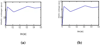
Fig 19. RMS voltage (pu) at generator bus (a) without MPFC (b) with MPFC
(a) (b)
Fig 20. RMS voltage (pu) at load bus (a) without MPFC (b) with MPFC
(a) (b)
Fig 21. RMS current (pu) at generator bus (a) without MPFC (b) with MPFC
(a) (b)
Fig 22. RMS current (pu) at load bus (a) without MPFC (b) with MPFC
As shown in figs.19 to 22, with using the proposed MPFC scheme, the remote short circuit fault has not any effect on the values of RMS voltage and RMS current of generator and load buses, so these schemes can be considered a good power quality mitigation method.
C. Hybrid Local Load Excursions Case:
The real time dynamic responses of the system for a load excursion are obtained for the following time sequences
At t = 0.1 sec, linear load is disconnected for duration of 0.05 sec
At t = 0.2 sec, nonlinear load is disconnected for a duration of 0.05 sec
At t = 0.3 sec, the induction motor torque is decreased by 50% for a duration 0.05 sec.
At t = 0.4 sec, the induction motor torque is Increased by 50% for duration 0.05 sec.
0 0.2 0.4 0.6 0.8 1 -0.05
0 0.05
time(sec)
st
a
b
le
vo
lta
g
e
0 0.2 0.4 0.6 0.8 1
0 0.05 0.1 0.15 0.2
time (sec)
st
a
b
le
vo
lta
g
e
0 0.1 0.2 0.3 0.4 0.5
0 0.5 1 1.5
time (sec)
RM
S
vo
lta
g
e
(
p
u
)
0 0.1 0.2 0.3 0.4 0.5 0
0.5 1 1.5
time (sec)
RM
S
vo
lta
g
e
(
p
u
)
0 0.1 0.2 0.3 0.4 0.5
0 0.5 1 1.5
time (sec)
RM
S
vo
lta
g
e
(
p
u
)
0 0.1 0.2 0.3 0.4 0.5
0 0.5 1 1.5
time (sec)
RM
S
vo
lta
g
e
(
p
u
)
0 0.1 0.2 0.3 0.4 0.5
0 0.2 0.4 0.6 0.8
time (sec)
RM
S
cu
rr
e
n
t
(p
u
)
0 0.1 0.2 0.3 0.4 0.5
0 0.1 0.2 0.3 0.4 0.5
time (sec)
RM
S
cu
rr
e
n
t
(p
u
)
0 0.1 0.2 0.3 0.4 0.5 0
0.2 0.4 0.6 0.8 1
time (sec)
RM
S
cu
r
r
e
n
t
(
p
u
)
0 0.1 0.2 0.3 0.4 0.5 0
0.2 0.4 0.6 0.8 1
time (sec)
RM
S
cu
r
r
e
n
t
(
p
u
[image:5.612.55.258.602.691.2]International Journal of Emerging Technology and Advanced Engineering
Website: www.ijetae.com (ISSN 2250-2459,ISO 9001:2008 Certified Journal, Volume 3, Issue 9, September 2013)
381
[image:6.612.51.547.84.709.2](a) (b)
Fig 23. RMS voltage (pu) at generator bus (a) without MPFC (b) with MPFC
[image:6.612.53.310.97.725.2](a) (b)
Fig 24. RMS voltage (pu) at load bus (a) without MPFC (b) with MPFC
[image:6.612.337.563.266.355.2](a) (b)
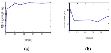
Fig 25. RMS current (pu) at generator bus (a) without MPFC (b) with MPFC
(a) (b)
Fig 26. RMS current (pu) at load bus (a) without MPFC (b) with MPFC
(a) (b)
Fig 27. RMS current (pu) for linear loads (a) without MPFC (b) with MPFC
(a) (b)
Fig 28. RMS current (pu) for non-linear loads (a) without MPFC (b) with MPFC
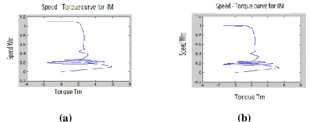
(a) (b)
Fig 29. Speed torque relation of induction motor (a) Without MPFC (b) with MPFC
The RMS of voltage and current waveforms at generator and load buses under load excursions are depicted in Figs 23 to 26. The linear and nonlinear load RMS current waveforms are shown in Fig. 27 & 28 and the speed-torque relationship of induction motor (IM) is shown in Fig. 29.
Table I The Transmission Line Losses
Comparing the dynamic response results without and with using the proposed MPFC under three study cases; normal operation, short circuit fault conditions and hybrid load excursion, it is quite apparent that the proposed MPFC enhanced the power quality, improved power factor voltage and reduced the transmission line losses.
P loss Q loss S loss
Case1 Without 0.0892 0.1542 0.1752
with 0.001 0.007 0.0071
Case 2 Without 0.1954 0.3467 0.398
with 0.001 0.007 0.0071
Case 3 Without 0.1018 0.1869 0.2128
with 0.0011 0.0065 0.0066
0 0.1 0.2 0.3 0.4 0.5 0.6 0.7 0 0.5 1 1.5 time (sec) RM S vo lta g e ( p u )
0 0.1 0.2 0.3 0.4 0.5 0.6 0.7 0 0.5 1 1.5 2 2.5 time (sec) RM S vo lta g e ( p u )
0 0.1 0.2 0.3 0.4 0.5 0.6 0.7 0 0.5 1 1.5 time (sec) RM S vo lta g e ( p u )
0 0.1 0.2 0.3 0.4 0.5 0.6 0.7 0 0.5 1 1.5 2 time (sec) RM S vo lta g e ( p u )
0 0.1 0.2 0.3 0.4 0.5 0.6 0.7
0 0.2 0.4 0.6 0.8 time (sec) RM S cu rr e n t (p u )
0 0.1 0.2 0.3 0.4 0.5 0.6 0.7 0 0.5 1 1.5 time (sec) RM S cu r r e n t ( p u )
0 0.1 0.2 0.3 0.4 0.5 0.6 0.7 0 0.2 0.4 0.6 0.8 time (sec) RM S cu r r e n t ( p u )
0 0.1 0.2 0.3 0.4 0.5 0.6 0.7 0 0.5 1 1.5 2 2.5 time (sec) RM S cu rr e n t (p u )
0 0.1 0.2 0.3 0.4 0.5 0.6 0.7 0 0.02 0.04 0.06 0.08 time (sec) RM S cu rr e n t
0 0.1 0.2 0.3 0.4 0.5 0.6 0.7 0 0.05 0.1 time (sec) RM S cu r r e n t ( p u )
0 0.1 0.2 0.3 0.4 0.5 0.6 0.7 0 1 2 3 time (sec) RM S cu r r e n t ( p u )
[image:6.612.344.551.466.642.2]International Journal of Emerging Technology and Advanced Engineering
Website: www.ijetae.com (ISSN 2250-2459,ISO 9001:2008 Certified Journal, Volume 3, Issue 9, September 2013)
382
VI. CONCLUSION
This paper presents a novel modulated switched power filter compensator (MPFC) scheme is controlled by a dynamic tri-loop dynamic error driven PID controller. The proposed FACTS based scheme can be extended to other distributed/dispersed renewable energy interface and utilization systems and can be easily modified for other specific compensation requirements, voltage stabilization and efficient utilization. The proposed MPFC scheme has been validated for effective power quality improvement, voltage stabilization, and power factor correction and transmission line loss reduction when the system is extensively simulated in MATLAB/SIMULINK.
APPENDIX
1) Steam turbine: Pout = 600 MW, speed = 3600 rpm. 2) Synchronous generator: 3 phase, 1 pair of poles, Vg = 25kV (L-L), Sg = 600 MVA, Xd=1.79, Xd'=0.169, Xd"=0.135, Xq=1.71, Xq'=0.228,
Xq"=0.2, Xl=0.13.
3) Local Hybrid AC Load (90 MVA): Linear load: 30 MVA, 0.85 lag pf.
Non-linear load: P= 20 kW, Q=22.4 MVAR. Induction motor: 3phase, 30 MVA, no of poles=4,
Stator resistance and leakage inductance (Pu) Rs =0.01965, Ls=0.0397
Rotor resistance and leakage inductance (Pu) Rr = 0.01909, Lr=0.0397
Mutual inductance Lm (Pu) =1.354
4) Transmission Line: VL-L = 500 kV, 300 km length,
R/km=0.01273 Ω, L/km=0.9337 mH
5) Infinte Bus: VL-L = 500 kV
6) MPFC: Cs = 30μF, Cf1 = Cf2 = 125μF,
Rf = 0.25Ω, Lf =3mH
7) Controller gains (figure 2): γvg=1, γig=0.5, γpg=0.25,
γvgrip=1, γig-rip=1, γpg-rip=0.5, Ke=0.1, kp=10, ki=5,
kd=0.5 and PWM frequency fs=1750 Hz.
REFERENCES
[1] J. Arrillaga, D. A. Bradley, P. S. Bodge, Power System Harmonics,
Wiley, 1985.
[2] K. Eichert, T. Mangold, M. Weinhold, ―Power Quality Issues and
their Solution‖, in VII Seminario deElectrónica de Potencia, Valparaíso, Chile, Abril 1999.
[3] G. Joos, L. Morán, ―Principles of Active Power Filters‖, Tutorial Course Note. of IEEE Ind. Appl. Society Annual Meeting, Oct. 1998.
[4] W. M. Grady, M.J. Samotyj, A. H. Noyola, ―Survey of Active Power
Line Conditioning Methodologies,‖ in IEEE Trans. on Power Delivery, vol. 5, no 3, pp.1536-1542, July 1990.
[5] H. Akagi, ―New Trends in Active Filters for Power Conditioning,‖in
IEEE Trans. on Industry Applications, vol.32, no.6, pp1312-1322, Nov./Dec. 1996.
[6] M. Aredes, K. Heuman and E. Watanabe, ―An Universal Active
Power Line Conditioner,‖ in IEEE Trans. on Power Delivery, vol. 13, no 2, pp. 545-551, April 1998.
[7] L. Morán, L. Fernández, J. Dixon, R. Wallace, ―A
Simple and Low Cost Control Strategy for Active Power Filters Connected in Cascade‖, in IEEE Trans. on Industrial Electronics, vol. 44, no. 5, pp.621-629, Oct. 1997.
[8] A.Ametani,‖Harmonic reduction in thyristor converters by harmonic
current injection‖, IEEE Trans.power Appl.syst.95 (2),441-449(1976)
[9] L. Gyugi, and E.C.Strycula,‖Active ac power filters‖,IEEE-IAS
Ann, Meeting,529-535(1976)
[10] H. Fujita and H. Akagi, ―A practical approach to harmonic
compensation in power system-series connection of passive, active filters,‖ IEEE Trans. Ind. Applicat., vol. 27, no. 6, pp.1020–1025, Nov./Dec. 1991.
[11] A. M. Sharaf, Caixia Guoand Hong Huang, ―Distribution/Utilization
system voltage stabilization and power quality enhancement using intelligent smart filter‖, UPEC’95, England, UK, 1995.
[12] M. Aredes, K. Heumann, and E. H. Watanabe, ―An universal active
power line conditioner,‖ IEEE Trans.Power Delivery, vol. 13, no. 2, pp. 545–557, Apr. 1998.
[13] H. Fujita and H. Akagi , ―A hybrid active filter for damping of harmonic resonance in industrial power system,‖IEEE Trans. Power Electron., vol. 15, no. 2, pp. 215–222, Mar.2000.
[14] A. M. Sharaf, and G. Wang, "Wind Energy System Voltage and Energy Enhancement using Low Cost Dynamic Capacitor Compensation Scheme." Proceedings of the IEEE International
Conference on Electrical, Electronic and Computer
Engineering. pp. 804-807, 5-7 Sept. 2004.
[15] A. M. Sharaf and Khaled Abo-Al-Ez, ―A FACTS Based Dynamic
Capacitor Scheme for Voltage Compensation and Power Quality Enhancement‖, Proceedings of the IEEEISIE 2006 Conference, Montreal, Quebec Canada,July 2006.
[16] A. Sharaf, R. Chhetri, ―A novel dynamic capacitor
compensator/green plug scheme for 3-phase 4-wire utilization loads‖, Proceeding IEEE-CCECE conference, Ottawa, Ontario, Canada 2006.
[17] A.M. Sharaf, Hassan A. Mahasneh and Yevgen Biletskiy,―Energy
Efficient Enhancement in AC Utilization Systems‖ The 2007 IEEE Canadian Conference on Electrical and Computer Engineering CCECE 07, Vancouver, Canada, April 2007.
[18] A.M. Sharaf, W. Wang, and I.H. Altas, ―A Novel Modulated Power