International Journal of Emerging Technology and Advanced Engineering
Website: www.ijetae.com (ISSN 2250-2459,ISO 9001:2008 Certified Journal, Volume 3, Issue 10, October 2013)
98
Design, Static and Modal Analysis of A Propeller Shaft for
Reducing Vibrations Using Composite Damping
Srimanthula Srikanth
1, Jithendra Bodapalli
2, Avinash Gudimetla
31
Student of M.Tech (CAD/CAM) in Dept. Of ME, NCET College, Vegavaram.
2Assoc. Professor and HOD, Dept. Of ME, NCET College, Vegavaram 3Assoc. Professor, Dept. of ME, Pragati Engineering college, surampalem
Abstract
-
-
With the growing demand for the energy efficient and smart materials, the necessity for reducing the vibrations in the highly sophisticated parts of the machinery is playing a major role. High-technology structures often have stringent requirements for structural dynamics. Suppressing vibrations is crucial to their performance. Passive damping is used to suppress vibrations by reducing peak resonant response. Viscoelastic damping materials add passive damping to structures by dissipating vibration strain energy in the form of heat energy. The incorporation of damping materials in advanced composite materials offers the possibility of highly damped, light-weight structural components that are vibration-resistant.The main theme of the project is to analyze a shaft with and without damping material and also for various isotropic and orthotropic materials. Along with alloys of various materials, composite materials are also considered to analyze the case to increase its robustness. The materials used for shaft are steel, carbon Epoxy and E – Glass Epoxy. The model of a particular shaft is taken and analyzed using ANSYS. The structural analysis is done to verify the strength of the shaft and to compare the results for the three materials. Modal analysis is also done on the shaft to determine mode shapes and to find their frequencies.
Keywords— Viscoelastic damping, frequency, Propulsion Shaft, Damping Material, Carbon Epoxy, steel, Carbon Epoxy, E-Glass Epoxy
I. INTRODUCTION
All engineering structures experience vibratory motion whether in reference to the world’s tallest building or a printed circuit board in a flight control computer. The effect of operating environments and inherent dynamic behavior cause the transmission of periodic waves throughout a structure. In turn, the structure undergoes mechanical vibrations. These unwanted vibrations result in fatigue and catastrophic failure of structures. Hence, the control of vibrations is a serious concern for engineering design.
A structure subjected to oscillatory deformation consists of a combination of kinetic and potential energy. In the case of real structures consists of energy dissipative elements as some of the energy is lost in each cycle. The amount of energy dissipated is a measure of the structure’s inherent damping. Damping can be viewed as the conversion of mechanical energy of a vibrating structure into thermal energy, which ultimately is lost to the structure’s environment.
Vibration control can be accomplished through active and/or passive damping treatments. Active damping control involves the use of a feedback control system that senses structural vibrations and then calculates the necessary control input for actuators. On the other hand, passive damping control refers to a structure’s ability to damp its own oscillations as a result of its structural design, material properties, or by the incorporation of devices like coatings and elastomers that dissipate energy
.
II. LITERATURE SURVEY
International Journal of Emerging Technology and Advanced Engineering
Website: www.ijetae.com (ISSN 2250-2459,ISO 9001:2008 Certified Journal, Volume 3, Issue 10, October 2013)
99
A desirable packing geometry for the composite material is proposed, which is expected to produce maximum shear strain in the Viscoelastic damping matrix. A general method for modeling material damping in dynamical systems is presented and it is primarily concerned with a dissipation model based on Viscoelastic assumptions. Different numerical approaches for modeling and analyzing the behavior of structures having constrained layer damping. Two numerical studies are presented that reveal the accuracy limits of the different finite element modeling approaches for additive and integrally damped plate type structures. Now through the use of improved computational – based approaches (i.e. finite element method) along with the availability of reliable damping materials with accurate thermal and dynamic property characterizations, it is possible to incorporate damping treatments as part of the initial structural design process, thereby virtually eliminating sharp resonant peaks. Cylindrical shells with a constrained damping layer treatment are studied using three theories. Constrained layer damping in structures is a very popular method to control resonant amplitudes of vibration. Shells of revolution (e.g., cylindrical and conical) find wide application in the aerospace industry. An efficient method is described for finite element modeling of three-layer laminates containing a viscoelastic layer. Modal damping ratios are estimated from undamped normal mode results by means of the Modal Strain Energy (MSE) method. The solution for a radially simply supported shell has been obtained and the procedure for determining the damping effectiveness in terms of the system loss factor for all families of the modes of vibration in a multilayered shell with elastic and viscoelastic layers is reported. Approximately 85% of the passive damping treatments in actual applications are based on viscoelastic materials. The solution for the vibration and damping analysis of a general multilayered cylindrical shell consisting of an arbitrary number of orthotropic material elastic and viscoelastic layers with simply supported end conditions has been reported. Damping mechanics for predicting the damped dynamic characteristics in special composite structures with compliant inter laminar damping layers are presented. Designed –in passive damping for structures is usually based on one of four technologies: Viscoelastic materials, viscous fluids, magnetic, or passive piezoelectrics. The technology of using viscoelastic materials for passive damping is discussed in more detail than the other methods since it is presently the most widely used type of damping technology. The effectiveness of damping treatments in structures is related to the amount of vibration energy converted into other forms of energy.
Two viscoelastic models, namely ADF and GHM, which account for frequency dependence and allow frequency and time domain analysis of hybrid active-passive damping treatments, is compared which is made of viscoelastic layers constrained with piezoelectric actuators. The ever increasing need to improve the efficiency of structural system places a growing importance on dynamic analysis in the design or development cycle. Damping analysis is performed by the complex stiffness (modulus and loss factor) approach (variation of material properties and damping factors with frequency is taken into account), and by consideration of the dissipation of vibratory energy through friction. It is well known that considerable reduction in resonant vibration can be realized by the use of highly damped viscoelastic materials as cores in sandwich structures. Such reductions are of practical interest in design applications where resonant excitation cannot be avoided. Embedding viscoelastic materials to dissipate energy within the structures provides a robust means of incorporating damping without encountering several of the common disadvantages associated with external damping treatments. A systematic analytical study of the improvement of damping in polymer composites at the micromechanical level under transverse normal loading by the use of special fiber coatings is described. The formulation of a theory for the prediction of damping and natural frequencies laminated composite beams with multiple viscoelastic damping layers are described.
III. OBJECTIVE
This project work expresses the difference between the structures with and without damping material. The effect of damping on the performance of isotropic (steel) and orthotropic (Carbon Epoxy & E-Glass Epoxy) structures is to be analyzed by using Finite Element Analysis. The values of the static deflection for Steel Shaft, Carbon Epoxy Shaft and E-Glass Epoxy Shaft are to be compared with and without visco elastic polymer (Rubber).
IV. NEED FOR DAMPING
International Journal of Emerging Technology and Advanced Engineering
Website: www.ijetae.com (ISSN 2250-2459,ISO 9001:2008 Certified Journal, Volume 3, Issue 10, October 2013)
100
Fig1: Boundary Excitation
The equation of motion of such a system can be written in the form:
0 ) w w )( i 1 ( k w
m 0
..
Where k, m and are the modal stiffness, mass and damping values, respectively. The ratio of the response of the mass to the input vibration, w/ wo is illustrated in forthcoming figures.
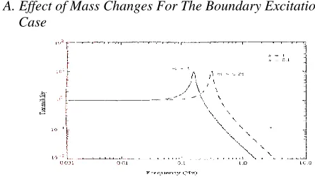
A. Effect of Mass Changes For The Boundary Excitation Case
Fig2: Temperature Vs Frequency for two masses
In the Fig.2 by keeping the stiffness and damping constant the effect of the structure can be seen by varying the mass. Here the same amount of response is occurred but at different frequency
.
B. Effect of Stiffness Changes for the Boundary Excitation Case
Fig3: Temperature Vs Frequency for two different stiffness values
In Fig.3, by keeping the mass and damping constant the effect of the structure can be seen by varying the stiffness. The response is same as that in the case of change of effect in mass.
[image:3.612.46.269.324.451.2]C .Effect of Damping Changes for the Boundary
Fig 4: Temperature Vs Frequency for two different damping values In this case by keeping the mass and stiffness constant the effect of the structure can be seen by varying the damping. In this case it reduces the maximum amplitude by increasing the damping. .
There are three different zones in the above figures.
One below the natural frequency
One above the natural frequency
One at the natural frequency
It is evident from the above figures that the stiffness and mass modifications affect the frequency range above resonance, whereas damping affects the response near resonance, and no important changes occur below the resonant frequency from changes in damping, mass or stiffness.
The primary effect of increased damping in a structure is a reduction of vibration amplitudes at resonance's, with corresponding decreases in stresses, displacements, fatigue, and sound radiations.
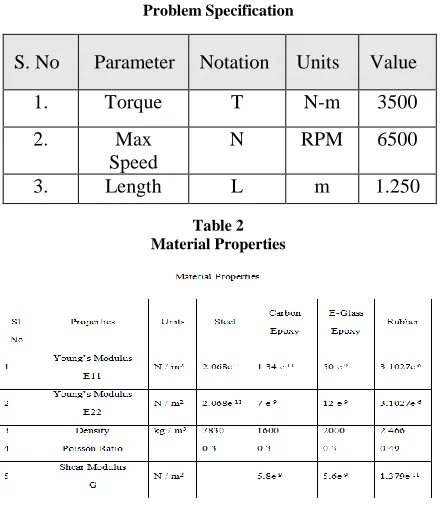
V. PROBLEM FORMULATION
A. Introduction to Propulsion Shaft:
International Journal of Emerging Technology and Advanced Engineering
Website: www.ijetae.com (ISSN 2250-2459,ISO 9001:2008 Certified Journal, Volume 3, Issue 10, October 2013)
101
Fig5: Pictorial representation of shaft transmission system. B. Problem Description:
[image:4.612.59.279.379.632.2]The one-piece hollow composite drive shaft should satisfy three design specifications, such as static torque transmission capability, torsional buckling capacity and the fundamental natural bending frequency. For given specification, the damping factor for Steel, carbon Epoxy and E-Glass Epoxy are to be calculated and compared with and without damping material (Rubber).
Table 1 Problem Specification
Table 2 Material Properties
VI. BRIEF OVER VIEW OF STRUCTURAL STATIC ANALYSIS
Static analysis is one in which the loads/boundary conditions are not the functions of time and the assumption here is that the load is applied gradually. The most common application of FEA is the solution of stress related design problems
.
Typically in a static analysis the kind of matrix solved is
[K] * [X] = [F]
Where K is called the stiffness matrix, X is the displacement vector and F is the load matrix. This is a force balance equation. Some times, the K matrix is the function X. Such systems are called non-linear systems.
Nodal Displacements ui, uj Nodal Forces fi, fj Spring constant k
Spring force displacement relationship F = k with = uj – ui
Where K = F/ (>0) is the force needed to produce a unit stretch.
Consider the equilibrium forces for the spring. At node i, we have
fi = -F = -k(uj – ui) = kui – kuj
And at node j,
fj = F = k(uj – ui) = - kui + kuj
Ductile material
Under combined static loading, the machine parts made of ductile material will fail by yielding. The working or allowable stress is therefore, passed on the yield point stress. The maximum shear stress theory will be used for the design because it is conservative and easy to apply.
Brittle materials
Failure in brittle materials, takes place by fracture. Brittle materials do not have a distinct yield point and so, the ultimate strength is used as the basis for determining the allowable or design stress. Separate design equations should be used in tension and compression, since for materials like cast iron; the ultimate compressive strength is considerably greater than the ultimate tensile strength. The maximum principal stress theory will be used for the design. Due consideration will be given to the sign of principal stresses. If both the principal stresses (2-D case) are of the same sign, the effect of the smaller stress is neglected. If the two principal stresses are of opposite sign, then the maximum principal stress theory does not give conservative results. In that case another equation should be used.
A. Static Analysis Comparison of Theoretical and Ansys Analysis
In this part static deflection of the steel shaft is calculated and compared with ANSYS results. The specification for the shaft is given in the Table 3. For calculating the deflection, the boundary condition is taken by considering its self weight.
S. No Parameter Notation Units Value
1. Torque T N-m 3500
2. Max Speed
N RPM 6500
International Journal of Emerging Technology and Advanced Engineering
Website: www.ijetae.com (ISSN 2250-2459,ISO 9001:2008 Certified Journal, Volume 3, Issue 10, October 2013)
[image:5.612.59.274.164.220.2]102
Table 3 Specification for Steel Shaft
VII. STEEL SHAFT
A. Steel Shaft without damping material
Material for Shell 99
In this case shell element is taken to calculate the deflection value for steel shaft. Here Shell element is taken due to specify the number of layers to include the damping polymer. Here steel shaft without damping material is considered and specifications are tabulated in table 3.
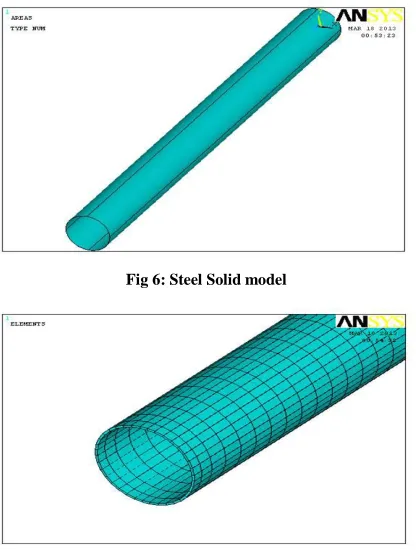
Fig 6: Steel Solid model
Fig7: Meshed Model
Using ANSYS the deflection value is calculated. The value is 0.252e-4m. The deformed shape of the shaft is shown in the Fig 7.
B. Steel Shaft with Damping Material
In this type a damping material (i.e.) Rubber is inserted between the two layers of shaft and the deflection value is calculated using ANSYS. The specification of the shaft with damping material is shown in the Table 4.
Table4
Specifications for Steel Shaft with Rubber Sl. No. Parameters Values
1 Outer Diameter 0.09024 m
2 Thickness of each
layer 1.05 e
-3 m
3 Number of layers 3 4 Damping Material Rubber 5 Element Shell 99
Sl. No.
Parameters
Values
1
Outer Diameter
0.09024 m
[image:5.612.65.273.343.618.2]International Journal of Emerging Technology and Advanced Engineering
Website: www.ijetae.com (ISSN 2250-2459,ISO 9001:2008 Certified Journal, Volume 3, Issue 10, October 2013)
103
[image:6.612.336.544.136.396.2]Fig8: Stacking Sequence for Steel Shaft with Rubber In the above Fig 8. Stacking sequence of the steel shaft with damping material is shown.
Fig 9: Deflection of Steel Shaft with Rubber
Using ANSYS the deflection value is calculated. The value is 0.41 e -4 m. The deformed shape of the shaft is shown in the Fig 9.
C. Carbon Epoxy Shaft without Damping Material
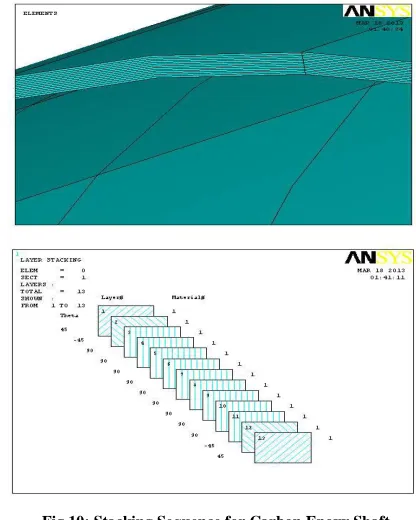
In this case Carbon Epoxy shaft is modeled with 13 layers by considering the shell element. The specifications are shown in the table5.
Table 5
Specification for Carbon Epoxy Shaft Sl. No. Parameters Values
1 Outer Diameter 0.09024 m
2 Thickness of each
layer 1.5 e
-4 m
3 Number of layers 13 4 Element Shell 99
[image:6.612.57.273.294.450.2]Fig 10: Stacking Sequence for Carbon Epoxy Shaft In the above Fig 10. The stacking sequence of the Carbon Epoxy shaft without damping material is shown
.
Fig 11: Static Deflection for Carbon Epoxy Shaft
The value is 0.376 e -4 m. The deformed shape of the shaft is shown in Fig 11.
D. Carbon Epoxy Shaft with Damping Material
[image:6.612.336.546.439.589.2]International Journal of Emerging Technology and Advanced Engineering
Website: www.ijetae.com (ISSN 2250-2459,ISO 9001:2008 Certified Journal, Volume 3, Issue 10, October 2013)
[image:7.612.55.282.157.249.2]104
Table 6
Specification for Carbon Epoxy Shaft with Rubber Sl. No. Parameters Values
1 Outer Diameter 0.09024 m
2 Thickness of each layer 1.5 e -4 m
3 Number of layers 14 4 Damping Material Rubber
5 Element Shell 99
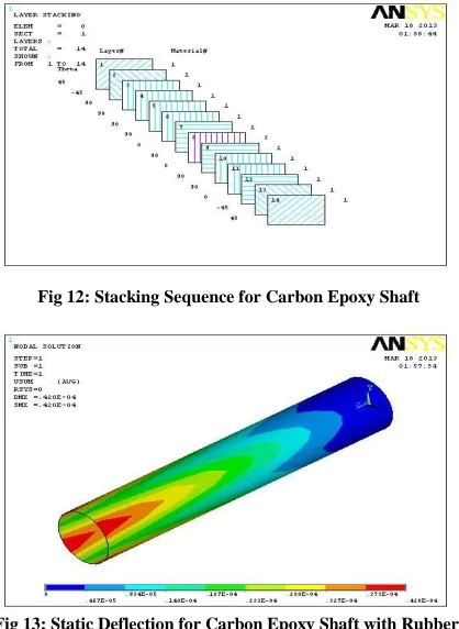
[image:7.612.64.273.296.582.2]The stacking sequence of the Carbon Epoxy shaft with damping material (Rubber) is shown in the fig 12. Here the 8th layer is the rubber.
Fig 12: Stacking Sequence for Carbon Epoxy Shaft
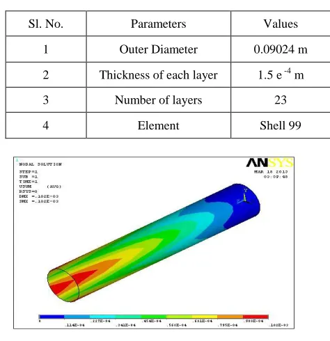
Fig 13: Static Deflection for Carbon Epoxy Shaft with Rubber. The value is 0.712 e -4 m. The deformed shape of the shaft is shown in the Fig 13.
E. E-Glass Epoxy Shaft without Damping Material
In this case E-Glass Epoxy shaft is modeled with 23 layers by using the shell 99 element. The specifications are shown in the table 7.
Fig14: Stacking Sequence Layers from 1 to 12
Fig 15: Stacking Sequence Layers from 13to23
The stacking sequence of the Carbon Epoxy shaft without damping material is shown in above figures.
Fig16: Static Deflection for E-Glass Epoxy Shaft
International Journal of Emerging Technology and Advanced Engineering
Website: www.ijetae.com (ISSN 2250-2459,ISO 9001:2008 Certified Journal, Volume 3, Issue 10, October 2013)
105 F. E-Glass Epoxy Shaft with Damping Material
[image:8.612.332.569.196.441.2]In this case E-Glass epoxy shaft is modeled with damping material (Rubber) and it is incorporated in between the layers. The specification of the shaft is shown in the table 8.
Table 7
Specification for E- Glass Epoxy Shaft Sl.
No. Parameters Values
1 Outer Diameter .09024 m
2 Thickness of each
layer 1.5 e
-4
m
3 Number of layers 24
4 Damping Material Rubber
5 Element Shell 99
Fig17: Stacking Sequence Layers from 1 to 13
Fig18: Stacking Sequence Layers from 14to24
The stacking sequence of the E-Glass Epoxy shaft with damping material (Rubber). Here the 12th layer is the rubber.
Table 8
Specification for E- Glass Epoxy Shaft with Rubber
Fig 19: Static Deflection for E-Glass Epoxy Shaft with Rubber The value is 0.102 e -3 m. The deformed shape of the shaft is shown in the Fig 19.
VIII. MODAL ANALYSIS
Any physical system can vibrate. The frequencies at which vibration naturally occurs, and the modal shapes which the vibrating system assumes are properties of the system, and can be determined analytically using Modal Analysis.
Modal analysis is the procedure of determining a structure's dynamic characteristics; namely, resonant frequencies, damping values, and the associated pattern of structural deformation called mode shapes. It also can be a starting point for another, more detailed, dynamic analysis, such as a transient dynamic analysis, a harmonic response analysis, or a spectrum analysis.
Modal analysis in the ANSYS family of products is a linear analysis. Any nonlinearities, such as plasticity and contact (gap) elements, are ignored even if they are defined. Modal analysis can be done through several mode extraction methods: subspace, Block Lanczos, Power Dynamics, Reduced, Unsymmetric and Damped. The damped method allows you to include damping in the structure.
Sl. No. Parameters Values
1 Outer Diameter 0.09024 m
2 Thickness of each layer 1.5 e -4 m
3 Number of layers 23
[image:8.612.57.282.208.714.2]International Journal of Emerging Technology and Advanced Engineering
Website: www.ijetae.com (ISSN 2250-2459,ISO 9001:2008 Certified Journal, Volume 3, Issue 10, October 2013)
106 A. Uses of Modal Analysis
Modal analysis is used to determine the natural frequencies and mode shapes of a structure. The natural frequencies and mode shapes are important parameters in the design of a structure for dynamic loading conditions. They are also required to do a spectrum analysis or a mode superposition harmonic or transient analysis. Another useful feature is modal cyclic symmetry, which allows reviewing the mode shapes of a cyclically symmetric structure by modeling just a sector of it.
B. Modal Analysis of Steel Shaft without Damping Material by Shell Element
In this part Modal analysis of the shaft is calculated using the same specifications given in the static analysis. Modal analysis is needed because the output of this analysis is used in the transient analysis to calculate the time step.
C. Modal Analysis of Steel Shaft Using Shell Element Without and With Rubber
In this case Steel shaft is modeled using Shell 99. The specifications used are same as in the Static Analysis
[image:9.612.319.550.136.646.2]Fig20: Modal Analysis for Steel Shaft using Shell 99 In this case Rubber is embedded in between the steel layers. The stacking Sequence and the specifications are same as in the Static Analysis
.
Fig 21: Modal Analysis for Steel Shaft with Rubber
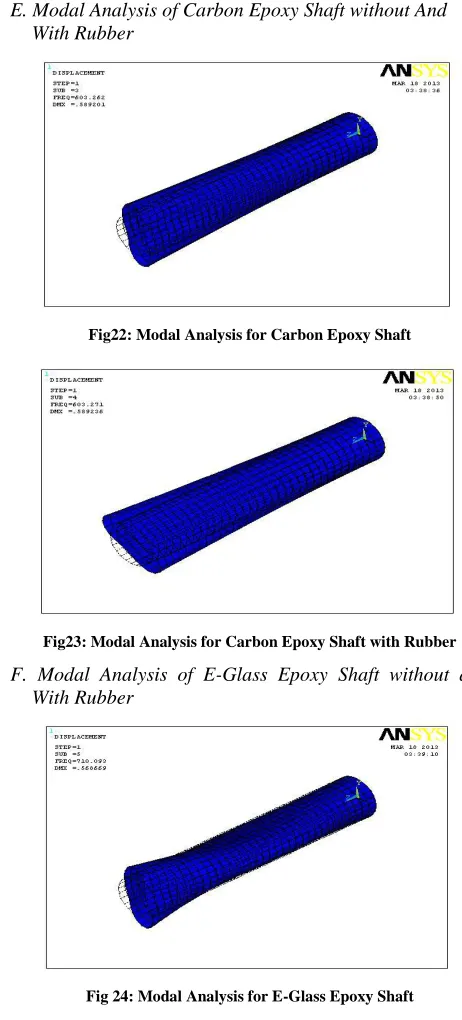
E. Modal Analysis of Carbon Epoxy Shaft without And With Rubber
Fig22: Modal Analysis for Carbon Epoxy Shaft
Fig23: Modal Analysis for Carbon Epoxy Shaft with Rubber F. Modal Analysis of E-Glass Epoxy Shaft without and
With Rubber
[image:9.612.60.272.582.703.2]International Journal of Emerging Technology and Advanced Engineering
Website: www.ijetae.com (ISSN 2250-2459,ISO 9001:2008 Certified Journal, Volume 3, Issue 10, October 2013)
107
Fig25: Modal Analysis for E-Glass Epoxy Shaft with Rubber IX. RESULTS
[image:10.612.327.567.167.450.2]In this case all the results of Static and Modal Analysis of Steel Shaft, Carbon Epoxy Shaft and E-Glass Epoxy shaft with and without damping polymer are tabulated and compared
.
Fig 26: Modal Analysis for Steel Shaft with Rubber A. Comparison of Steel Shaft with and Without Damping
[image:10.612.54.279.359.504.2]Material
Table 9
Comparison of Results for Steel Shaft Type of
the Shaft
Results
Steel without Viscoelastic
Material
Steel with Viscoelastic
Material
Static Deflection
(in m) 0.41 e
-4
0.252e-4
B. Comparison of Carbon Epoxy Shaft with and Without Damping Material
C. Comparison of E-Glass Epoxy Shaft with and Without Damping Material
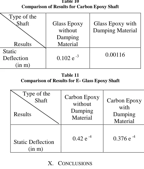
Table 10
Comparison of Results for Carbon Epoxy Shaft Type of the
Shaft
Results
Glass Epoxy without Damping
Material
Glass Epoxy with Damping Material
Static Deflection
(in m)
0.102 e -3 0.00116
Table 11
Comparison of Results for E- Glass Epoxy Shaft
X. CONCLUSIONS
As the aim of the project is to reduce the damping effects of the driven shaft, the major sources used for this purpose are composite materials. By using three different kind of composite materials steel, carbon epoxy, E-glass epoxy the project has been carried out. For controlling the damping effects by using passive damping the materials which reduces these damping like rubber are employed in the center of the shaft. Shaft is analyzed using layer stacking method in ANSYS software which utilizes finite element method technologies. These layer stacking techniques are employed for shafts with and without damping material. Static analysis is done for observing the steady loading conditions. The results have shown that the shaft with damping material made of any composite material has less damping effects when compared with shaft without damping material. The results have clearly proved that the static deflection of the shaft made with three composite materials with damping material when compared with without damping material. For the purpose of dynamic loading conditions and for determining natural frequencies, mode shapes modal analysis is also done.
Type of the Shaft
Results
Carbon Epoxy without Damping
Material
Carbon Epoxy with Damping
Material
Static Deflection (in m)
[image:10.612.50.287.563.639.2]International Journal of Emerging Technology and Advanced Engineering
Website: www.ijetae.com (ISSN 2250-2459,ISO 9001:2008 Certified Journal, Volume 3, Issue 10, October 2013)
108
The final result of the project is the shaft made with composite material and damping material has less damping effects compared with composite material shaft.
REFERENCES
[1] Autar K. Kaw, "Mechanics of Composite Materials", CRC press, 1997.
[2] Ahid D. Nashif, David I. G. Jones and John P. Henderson, ―Vibration Damping‖, John Wiley & Sons Publication, 1985, Newyork.
[3] C. T. Sun and Y. P. Lu, "Vibration Damping of Structural Elements", Prentince Hall PTR, New Jeresy, 1995.
[4] K. L. Napolitano, W. Grippo, J. B. Kosmatka and C. D. Johnson, ―A comparison of two cocured damped composite torsion shafts‖, Composite Structures, Vol. 43, 1998, pp. 115-125.
[5] J. M. Biggerstaff and J. B. Kosmatka, ―Damping Performance of Cocured Composite Laminates with Embedded Viscoelastic Layers‖, Journal of Composite Materials, Vol. 32, No.21/ 1998.
[6] Jin Kook Kim, Dai Gil Lee, and Durk Hyun Cho, 2001, ―Investigation of Adhesively Bonded Joints for Composite Propeller shafts‖, Journal of Composite Materials, Vol.35, No.11, pp. 999-1021.
[7] T. E. Alberts and Houchun Xia, ―Design and Analysis of Fiber Enhanced Viscoelastic Damping Polymers‖, Journal of Vibration and Acoustics, Vol. 117, October 1995, pp. 398-404.
[8] K. J. Buhariwala and J. S. Hansen, "Dynamics of Viscoelastic Structures", AIAA Journal, Vol. 26, February 1988, pp 220-227. [9] J. B. Kosmatka and S. L. Liguore, ―Review of Methods for
Analyzing Constrained Layer Damped Structures‖, Journal of Aerospace Engineering, Vol.6, No.3, July 1993, pp. 268-283. [10] T. C. Ramesh and N. Ganesan, ―Vibration and Damping Analysis of