International Journal of Emerging Technology and Advanced Engineering
Website: www.ijetae.com (ISSN 2250-2459, ISO 9001:2008 Certified Journal, Volume 6, Issue 3, March 2016)
210
Load Frequency Control in an Interconnected Hydro Power
System with SMES and SCES Units
V. Rajaguru
1, R. Sathya
2, Tesfaye Nafo Tefera
31
Lecturer, Department of Electrical & Computer Science Engg., Debre Berhan University, Debre Berhan, Ethiopia
2Assistant Professor, Department of EEE, Krishnasamy College of Engg & Tech., Cuddalore, India 3Scientific Director, Institute of Technology, Debre Berhan University, Debre Berhan, Ethiopia
Abstract—In the power system, any sudden changes in the load leads to frequency deviation. But the frequency should remain nearly constant for the satisfactory operation of a power system. So the Load Frequency Control (LFC) is an important issue in interconnected power systems. Energy storage units are very important for damping out the oscillations due to sudden changes in the power system. The addition of small capacity energy storage unit in each area of the power system can effectively restrain the system oscillations. Hence in this paper, the Superconducting Magnetic Energy Storage (SMES) Units and Super Capacitor Energy Storage (SCES) Units are incorporated in the Load Frequency Control model of two area interconnected hydro power system. The proposed work consist of two area interconnected hydro power system with SMES and SCES units has been designed to improve the dynamic performance of the system and also Integral Square Error (ISE) technique is used to obtain the optimal integral gain settings. The simulation result shows that the Load Frequency Control in an interconnected hydro power system with SCES units is considerably improved the system dynamics such as peak overshoot, settling time and frequency oscillations as compared to that of the system with SMES units and also the system without SMES and SCES units.
Keywords— Energy storage units, interconnected hydro power system, Integral Square Error technique, Load Frequency Control, Superconducting Magnetic Energy Storage Unit, Super Capacitor Energy Storage Unit.
I. INTRODUCTION
Load Frequency Control introduces as the most important term in power system so as to supply reliable and quality power supply to the consumers. Any change in the system loads, may be cause to abnormal operation of the system. In order to overcome from this problem, using the Load Frequency Control is essential. Maintaining frequency and power interchanges with interconnected control areas at the scheduled values are the main task of a Load Frequency Control. A lot of research work has been made in this area are as follows.
International Journal of Emerging Technology and Advanced Engineering
Website: www.ijetae.com (ISSN 2250-2459, ISO 9001:2008 Certified Journal, Volume 6, Issue 3, March 2016)
211
A comprehensive digital computer model of a two area interconnected power system including the Governor Dead Band (GDB) non-linearity, steam reheat constraints and the boiler dynamics is developed. The improvement in AGC with the addition of a small capacity SMES unit is studied [11].
II. TRANSFER FUNCTION MODEL OF TWO –AREA
INTERCONNECTED HYDRO POWER SYSTEM
A two area system consists of two single area systems, Connected through a power line called tie-line, is shown in the Fig.1. Each area feeds its user pool, and the tie line allows electric power to flow between the areas. Information about the local area is found in the tie line power fluctuations. It is conveniently assumed that each control area can be represented by and equivalent turbine, generator and governor system. Fig.1 shows the block diagram representing the two area interconnected hydro power system. This model includes the conventional integral controller gains (K11, K12). Each power area has a number of generators which are closely coupled together so as to form a coherent group. Such a coherent area is called a control area in which the frequency is assumed to be same.
III. INTEGRAL CONTROLLER
The integral control composed of a frequency sensor and an integrator. The frequency sensor measures the frequency error Δf and this error signal is fed into the integrator.
The input to the integrator is called Area Control Error (ACE). The ACE is the change in area frequency, which when used in an Integral-control loop, forces the steady-state frequency error to zero.
The integrator produces a real-power command signal ΔPc and is given by
(1) dt f c
P
K i
(2) dt ACE K i
Where,
ΔPc = input of speed –changer Ki = integral gain constant.
The value of Ki is so selected that the response will be damped and non-oscillator. For conventional Integral controller, the gains KI have to be determined by using Integral Square Error (ISE) criterion. The objective function used for this technique is
(3) )dt 2 1 ΔPtie t
0 F 2 1 (Δ J
Where,
F1= change in frequency in area 1 Ptie = change in tie-line power.
The optimum values of KI for the system with and without energy storage units are found to be 0.03, 0.04 & 0.02 respectively.
International Journal of Emerging Technology and Advanced Engineering
Website: www.ijetae.com (ISSN 2250-2459, ISO 9001:2008 Certified Journal, Volume 6, Issue 3, March 2016)
212
IV. SMESMODEL
The Fig.2 shows the basic configuration of a SMES unit in the power system. The superconducting coil can be charged to a set value (which is less than the full charge) from the utility grid during normal operation of the grid. The DC magnetic coil is connected to the AC grid through a Power Conversion System (PCS) which includes an inverter/rectifier. Once charged, the superconducting coil conducts current, which supports an electromagnetic field, with virtually no losses. The coil is maintained at extremely low temperature (below the critical temperature) by immersion in a bath of liquid helium.
When there is a sudden rise in the demand of load, the stored energy is almost immediately released through the PCS to the grid as line quality AC. As the governor and other control mechanisms start working to set the power system to the new equilibrium condition, the coil charges back to its initial value of current. Similar is the action during sudden release of loads. The coil immediately gets charged towards its full value, thus absorbing some portion of the excess energy in the system, and as the system returns to its steady state, the excess energy absorbed is released and the coil current attains its normal value. The operation of SMES units, that is, charging, discharging, the steady state mode and the power modulation during dynamic oscillatory period are controlled by the application of the proper positive or negative voltage to the inductor. This can be achieved by controlling the firing angle of the converter bridges.
Fig.2 Configuration of SMES unit
Neglecting the transformer and the converter losses, the DC voltage is given by
Ed2VdoCosα2IdRc (4)
Where, Ed = DC voltage applied to the inductor (KV)
α = firing angle (degree)
Id = current through the inductor (KA) Rc = equivalent commutating resistance (Ω)
Vdo= maximum open circuit bridge voltage of each six pulse convertor at α=0 degree (KV).
The inductor is initially charged to its rated current, Ido by applying a small positive voltage. Once the current has attained the rated value, it is held constant by reducing voltage ideally to zero since the coil is superconducting. A very small voltage may be required to overcome the commutating resistance.
The energy stored at any instant,
(5) MJ , ) LI 2d ( 2 1 L
W
Where, L = inductance of SMES, in Henry Id = current through the inductor (KA).
In LFC operation, the Ed is continuously controlled by the input signal to the SMES control logic. The inductor current must be restored to its nominal value quickly after a system disturbance so that it can respond to the next load disturbance immediately. Thus, in order to improve the current restoration to its steady state value the inductor current deviation is used as a negative feedback signal in the SMES control loop. Based on the above discussion, the converter voltage deviations applied to the inductor and the inductor current deviations are described as follows:
(7) (S) di ΔE i SL 1 (S) di ΔI (6) (S) di ΔI dci ST 1 id K (S) SMESi U dci ST 1SMES K (S) di ΔE Where
∆Edi (s) = Converter voltage deviation applied to inductor in SMES unit
KSMES = gain of control loop SMES
Tdci = convertor time constant in SMES unit
USMES = control signal of SMES unit
International Journal of Emerging Technology and Advanced Engineering
Website: www.ijetae.com (ISSN 2250-2459, ISO 9001:2008 Certified Journal, Volume 6, Issue 3, March 2016)
213
Fig.3 Block Diagram of SMES Unit
The ACEi is defined as follows:
(8) Ptie,i Δ Fi Δ Bi i
ACE
Where
Bi = Frequency bias in area i ∆Fi = Frequency deviation in area i
∆Ptie,i = Net tie line power flow deviation in area i.
The deviation in the inductor real power of SMES unit is expressed in time domain as follows:
(9) Idoi i SMES,
P Edi I diEdi
Where,
∆PSMESi = Deviation in the inductor real power
of SMES unit in area i.
This value is assumed to be positive for transfer from AC grid to DC. Fig. 3 shows the block diagram of SMES unit.
V. SCESMODEL
The block diagram of Super Capacitor Energy Storage (SCES) Unit is shown in Fig.4. Either frequency deviation or Area Control Error (ACE) can be used as the control signal to the SCES unit (Δerrori = Δfi or ACEi). Edi is then continuously controlled in accordance with this control signal. For the ith area, if the frequency deviation Δfi (i.e., Δerrori = Δfi).
Of the power system is used as the control signal to SCES, then the deviation in the current, ΔIdi is given by
(10) ] di E vdi K if . SCESi [K DCi ST 1 1 di
ΔI
If the tie-line power flow deviations can be sensed, then the Area Control Error (ACE) can be fed to the SCES as the control signal (i.e., Δerrori = ACEi). Being a function of tie-line power deviations, ACE as the control signal to SCES, may further improve the tie-power oscillations. Thus, ACE of the two areas are given by
(11) 2 1, j i, ; ij tie if . i B i
ACE P
Where, ΔPtie ij is the change in tie-line power flow out of area i to j.
Thus, if ACEi is the control signal to the SCES, then the deviation in the current ΔIdi would be
(12) 1,2 j i, ; ] di E vdi K i . SCESi [K DCi ST 1 1 di
ΔI
ACE
International Journal of Emerging Technology and Advanced Engineering
Website: www.ijetae.com (ISSN 2250-2459, ISO 9001:2008 Certified Journal, Volume 6, Issue 3, March 2016)
214
Fig.4 Block Diagram of SCES Unit
VI. COMPARISON OF SMESAND SCESUNITS
The following table shows the comparison of various parameter of SMES & SCES unit.
Table.I
Comparison of SMES and SCES unit
S.No Parameters SMES SCES
1 Typical Range 1-100 MW 1-250KW
2 Power Density (kW/M3) >530 >176678
3 Energy Density (kW-h/M3) >7.07 >53
4 Emission No No
5 Life time ~30 Years ~30 Years
6 Losses/W 17mW 0.004mW
7 Electrical Efficiency 90% >95%
8 Levelized annual cost ($/kW-h) 200 85
9 Response Time Milliseconds Milliseconds
10 Backup Time Seconds Seconds
11 Applications Peak saving, Power quality
Emergency power sources, Power
quality, Defence
12 Advantages
Storage time is very high,
Independent of the number of
charges & discharges
High charge and discharge current,
Maintenance free, Very high
International Journal of Emerging Technology and Advanced Engineering
Website: www.ijetae.com (ISSN 2250-2459, ISO 9001:2008 Certified Journal, Volume 6, Issue 3, March 2016)
215
VII. SIMULATION MODEL AND RESULTS
International Journal of Emerging Technology and Advanced Engineering
Website: www.ijetae.com (ISSN 2250-2459, ISO 9001:2008 Certified Journal, Volume 6, Issue 3, March 2016)
216
International Journal of Emerging Technology and Advanced Engineering
Website: www.ijetae.com (ISSN 2250-2459, ISO 9001:2008 Certified Journal, Volume 6, Issue 3, March 2016)
217
International Journal of Emerging Technology and Advanced Engineering
Website: www.ijetae.com (ISSN 2250-2459, ISO 9001:2008 Certified Journal, Volume 6, Issue 3, March 2016)
218
0 50 100 150 200 250 300
-0.5 -0.4 -0.3 -0.2 -0.1 0 0.1 0.2 Time(s) c h a n g e i n f re q u e n c y (D E L F 1 ), H z
FREQUENCY DEVIATION IN AREA 1
with SCES with SMES without
Fig .6 (a)Frequency Response of Area-1 (∆f1)
0 50 100 150 200 250 300
-0.5 -0.4 -0.3 -0.2 -0.1 0 0.1 0.2 Time(s) c h a n g e i n f re q u e n c y (D E L F 2 ), H z
FREQUENCY DEVIATION IN AREA 2
with SCES with SMES without
Fig. 6 (b)Frequency Response of Area-2 (∆f2)
0 50 100 150 200 250 300
-4 -3 -2 -1 0 1 2 3 4x 10
-5 Time(s) c h a n g e i n t ie l in e p o w e r( D E L P ti e ), P U .M W
TIE-LINE POWER DEVIATION
with SCES with SMES without
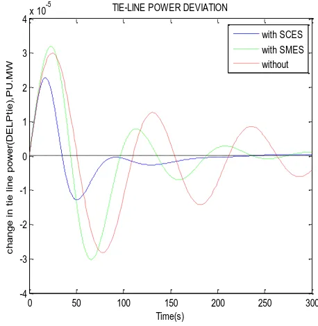
Fig.6 (c)Tie line power deviation of area-1 & area-2 (∆ptie 1, 2)
The fig.5 (a, b & c) shows the simulation diagram of Load Frequency Control in an interconnected hydro power system without & with SMES and SCES unit.
Fig.6 (a, b, & c) shows the simulation results of two area interconnected hydro power system with SCES & SMES unit and also for without SCES & SMES unit, considering Integral controller. Fig.6 (a & b) shows the frequency response of area-1 (i.e. ∆f1) and area-2 (i.e. ∆f2) for the system with SCES and SMES unit and also for the system without energy storage units. And the fig.6 (c) shows the tie line power deviation (∆ptie 1,2) for the system with and without energy storage units. Thus, from the Simulation Results, We say that the dynamic performance (such as frequency oscillation, peak overshoot and settling time) of the hydro power system is significantly improved when the SCES units are incorporated in a system.
VIII. CONCLUSION
[image:9.612.337.566.140.375.2] [image:9.612.60.287.141.376.2] [image:9.612.59.278.401.656.2]International Journal of Emerging Technology and Advanced Engineering
Website: www.ijetae.com (ISSN 2250-2459, ISO 9001:2008 Certified Journal, Volume 6, Issue 3, March 2016)
219
The simulation model consists of identical hydro units (two units per area) with and without energy storage units (SMES & SCES units) are considered for this study. And also the system performance is observed for 1% step load disturbance. In addition to this, Integral Square Error technique is used to obtain the conventional integral controller gains. The simulation results show that the dynamic performance of the system is significantly improved in terms of frequency oscillations, peak overshoot and settling time when the SCES units are incorporated in a two area interconnected hydro power system rather than the system with SMES units and without SMES & SCES units.
Appendix
A.1 Data for the two-area interconnected hydro power system
Pr1= Pr2 = 2000MW, T1= 41.6 sec, T2 = 0.513 sec,
TR = 5 sec, TW = 1 sec, H = 5 sec, D = 8.33*10-3 Pu. MW/Hz,
B = 0.425 Pu.MW/Hz, R = 2.4 Hz/Pu.MW.
A.2 Data for SMES block
L =2.65 H, Tdc = 0.03 sec, KSMES = 50 KV/unit MW
Kdi = 0.2 KV/KA, Ido= 4.5 KA.
A.3 Data for SCES block
K vd = 0.1 KV/KA, K0 = 70 KV/Hz,
KSCES = 0.7 Hz/Pu. MW, TSCES = 0.01 sec,
C= 1 F, R= 100Ω.
REFERENCES
[1] Adhimoorthy Venkatachalam and Chidambaram Ilangi Akilandam,
―Dual Mode Two – Layer Fuzzy Logic Based Load – Frequency Controller for a Two – Area Interconnected Power System With Super Capacitor Energy Storage Units Using Control Performance Standards Criterion‖, International Journal of Engineering and Innovative Technology, Vol.2, No.12, pp. 162–173, 2013.
[2] Banerjee S, Chatterjee JK, Tripathy SC, ―Application of Magnetic
Energy Storage unit as Load-Frequency stabilizer‖, IEEE Transaction on Energy Conversion, Vol.5, No.1, pp. 46–51, 1990.
[3] Demiroren A, Yesil E, ―Automatic Generation Control with Fuzzy
Logic Controllers in the Power System including SMES units‖, Electrical Power and Energy Systems, Vol.26, No.1, pp. 291–305, 2004.
[4] Naimul Hasan, Ibraheem, Shuaib Farooq, ―Real time simulation of
Automatic Generation Control for interconnected power system‖, International Journal of Electrical Engineering and Informatics, Vol.4, No.1, pp.40-51, 2012.
[5] Prajod.V.S and Carolin Mabel.M, ―Design of PI controller using
MPRS method for Automatic Generation Control of hydro power system‖, International Journal of Theoretical and Applied Research in Mechanical Engineering, Vol.2, No.1, pp.1-7, 2013.
[6] Ramanand Kashyap and S.S.Sankeswari, ―A simulation model for
LFC using fuzzy PID with interconnected hydro power systems‖, International Journal of Current Engineering and Technology, Special Issue.3, pp. 183-86, 2014.
[7] Ramanand Kashyap, S.S.Sankeswari, B.A.Patil, ―Load Frequency
Control using fuzzy PI controller generation of interconnected hydro power system‖, International Journal of Emerging Technology and Advanced Engineering, Vol.3, No.9, pp.655-59, 2013.
[8] A. Ruby meena and S.Senthil kumar, ―Load Frequency Stabilization
of four area hydro thermal system using Superconducting Magnetic Energy Storage System‖, International Journal of Engineering and Technology, Vol.6, No.3, pp.1564-72, 2014.
[9] C. Srinivasa Rao, ―Improvement of Dynamic Performance of AGC
of Hydrothermal System Employing Capacitive Energy Storage and TCPS‖, Innovative System Design and Engineering, Vol.2, No.6, pp. 63-71, 2011.
[10] A.Suresh Babu, Ch.Saibabu, S.Sivanagaraju, ―Implementation of
load following in multiarea hydrothermal system under restructured environment‖, International Journal of Engineering Sciences and Emerging Technologies, Vol.3, No.1, pp.13-21, 2012.
[11] Tripathy SC, Balasubramanian R, Chanramohanan Nair PS, ―Effect
of Superconducting Magnetic Energy Storage on Automatic Generation Control considering governor dead band and boiler dynamics‖, IEEE Transaction on Power Systems, Vol.3, No.7, pp.1266–73, 1992.
BIOGRAPHIES
V.Rajaguru received B. E. degree in Electrical and Electronics Engineering in 2006 from Annamalai University and M.E degree in Power Systems Engineering in 2009 from Annamalai University, India. He is currently working as a Lecturer in Electrical and Computer Science Engineering Department at Debre Berhan University, Debre Berhan, Ethiopia.
R.Sathya received B. E. degree in Electrical and Electronics Engineering in 2007 from Annamalai University and M.E degree in Power Systems Engineering in 2009 from Annamalai University, India. She is currently working as a Assistant Professor in Krishnasamy College of Engineering & Technology, Cuddalore,TamilNadu, India.
Tesfaye Nafo Tefera received B. E. degree in Electrical & Electronics Technology in 2005 from Adama Science & Technology University and M.Tech degree in Power & Energy Systems in 2010 from
National Institute of Technology, Karnataka