2018 International Conference on Applied Mechanics, Mathematics, Modeling and Simulation (AMMMS 2018) ISBN: 978-1-60595-589-6
Polarization Re-configurable Antenna Using SPDT Switch with
Off-Centered Fed
Peng DU, Xiao-lin YANG
*and Xue-lin LIU
School of Physical, University of Electronic Science and Technology of China, Chengdu, 610054, China
*Corresponding author
Keywords: Circular polarization, Reconfigurable antenna, Single-pole double-throw (SPDT) switch.
Abstract. This letter proposed a novel circular polarization (CP) reconfigurable antenna with off-centered fed. The off-centered feed line is designed to separate two orthogonal modes produced by the antenna with 90 degree phase difference, which could form a circular polarization wave. By controlling the state of a single-pole double-throw (SPDT) switch, different RF paths can be chose and the antenna can work in left-hand circular polarization (LHCP) mode or right-hand circular polarization (RHCP) mode with the 3-dB axial ratio (AR) bandwidth of 16.3%.When the SPDT is left turn-on, the antenna in the direction of Z axis works in LHCP and in negative direction of Z axis works in RHCP. The switch is directly driven by digital signal and no bias network is needed. The measured results are agreed well with the simulations. This proposed antenna is suitable for WLAN 5.2 GHz/5.8 GHz applications.
Introduction
In modern wireless communication system, reconfigurable antenna has attracted much attention for its advantages of miniaturization and multi-function. The polarization reconfigurable antenna is rationally used to realize the signal transmitting or receiving diversity so as to eliminate the multipath effect and improve the performance of wireless communication system. In space applications, launching, receiving, and reusing the same spectrum scope can increase the system capacity. Thus the study on the polarization reconfigurable antenna is of significant value.
In recent years, some new methods are used to achieve polarization reconfigurability of the antenna. Liquid crystal technology is exploited to dynamically change polarization state by electronically controlling the biasing voltage [1]. Reference [2] proposed a planar polarization-reconfigurable metasurface (MS) antenna. By mechanically rotating the MS atop of the slot antenna, linear polarization, left-hand and right-hand circular polarizations can be achieved. However, electrically re-configurable antennas usually have narrow axial-ratio bandwidths and mechanically re-configurable antennas have complicated structure and occupy much space. Most of polarization re-configurable antennas are designed using PIN-diodes because of its low cost and easy integration [3-8]. While, direct-current (DC) biasing circuits are needed to bias the PIN- diodes. This may affect the performance of the antenna and increase the complexity of the communication system. In addition, PIN-diodes have high power loss which limits its application. In our previous work [9], a GaAs FET with high isolation and low insertion loss acting as SPDT switch has been used to realize frequency re-configurable antenna. Complicate DC biasing circuits and blocking capacity are not required which make antenna more compact and easy to fabricate. Therefore we are considering using GaAs FET in polarization re-configurable antenna.
with perturbative stubs is introduced to separate two orthogonal modes and make the antenna produce CP wave. A small package SPDT switch is used between the feed line and the radiation strip. By choosing the state of the SPDT switch, the antenna can operate in two modes: a LHCP mode (5.03-5.87 GHz), and a RHCP mode (5.06-5.91 GHz), which can be applied to WLAN 5.2 GHz/5.8 GHz system.
Antenna Design
Antenna Structure
The proposed antenna is constructed on a Rogers Duroid5880 substrate with the size of 30 mm×28 mm and the thickness of 0.254 mm. The dielectric constant of the substrate is 2.2, and the loss tangent is 0.0009. The antenna is fed by a 50Ω CPW transmission line with a gap of 0.1 mm and the width of 4.8 mm. In order to obtain better impedance matching, between CPW line and radiation strip lines, an exponential curve shape transmission (ET) line is added. Two orthogonal radiation strip lines, which in parallel with the edge of the square slot in ground plane, connected with the ET line by GaAs FET. When the left/right radiation strip line connected with the ET line by controlling the FET, the antenna can work in the RHCP/LHCP mode. Two rectangle shape stubs are placed in the edges of the square slot to adjust the axial ratio of the antenna. Fig. 1(a) shows the geometry of proposed antenna worked in the LHCP mode and the optimized parameters.
Figure 1. (a) Geometry of the proposed antenna; (b) The enlargement of the SPDT switch. [W=30, W1=4.8, L=28, L1=0.5,
L2=5, L3=1, L4=2, L5=4.3, r1=r2=15, r3=14.5, r4=15, X1=2, X2=10.5, X3=1 (units in millimeters)].
W L r1 r4 L2 L5 L4 X3 X1 W1 r2 r3 L3 X2 L1 Y X
.
Z [image:2.595.187.411.351.703.2]SPDT Switch
Figure 1(b) displays the antenna with a SPDT switch and the enlargement of the switch between the feed line and the radiation strip-lines. The SPDT switch is a PHEMT GaAs FET (SKY13298-360LF) produced by Skyworks company [12]. It has a high isolation of 30 dB, and low insertion loss of 0.7 dB at 5.5 GHz. The feed line is connected to the RF input port of the switch (RFC), and the radiation strip lines are respectively connected to the RF output port (RF1 and RF2). The GND pin, VBIAS pins, and control pins (A and B) of the switch are connected to the behind pads through via. If VA (voltage at A port) is high level (1.8-3.3 V) and VB (voltage at A port) is low level (0 V), the RF signal path is from RFC to RF1, and the antenna works in LHCP mode. While if VA is low level and VB is high level, the RF signal path is from RFC to RF2, and the antenna works in RHCP mode. (If the high level is greater than 3 V, the Bias line needn’t external voltage, but if not, 1.8V voltage is needed.)
Circular Polarization Mechanism
As we all known, two orthogonal linear polarization waves in the space, with equal amplitude and phase difference of 90 degree, can form a circular polarization (CP) wave. Based on this mechanism, some perturbation elements are introduced in the design of CP antenna. The design of this proposed antenna uses the method of off-centered fed which is the one of the perturbation methods to separate the two orthogonal modes, and make them produce a 90 degree phase difference for forming a circular polarization. The co-planar waveguide transmission line has the advantage of low-dispersion, which is conductive to design wide-band antenna. The effect of elements in the antenna will be discussed in part 3.
Simulation and Discuss
The Effect of Parameters
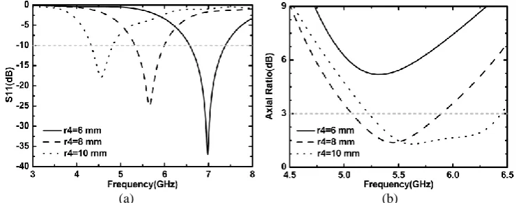
The performance of the antenna has been analyzed by CST Microwave Studio. During the simulation, it is found that the radiation is related to parameters of off-centered feed line. Figure2 shows the simulated reflection coefficient and axial ratio of the proposed antenna with different values of r4.
When r4 increases, namely the length of the feed line increases, the feed line inductance and the
capacitance between feed line and square slot (equivalent to multiple capacitors in parallel) also increase.
[image:3.595.109.485.541.689.2]
(a) (b)
Figure 2. The simulated (a) S11, and (b) axial ratio with different r4.
The value of L2 represents the intensity of exponential curve shaped transmission line. It has a small
Though some simulation results are not shown to make paper briefly, other parameters such as x2, W, and r1 also have effect on the proposed antenna. When the value of x2 decreases, the capacitance
between the rectangle shaped stub and off-centered feed line increases, the resonance frequency moves down and the CP bandwidth is expanded. W and the r1 (or r2) have a small influence on the
reflection coefficient, but also expand the CP bandwidth. The reason for these phenomenon is that separating the two orthogonal modes is a subtle operation, and varying a parameter will modify the impedance matching, which slightly impacts on radiating frequency.
Current Distribution
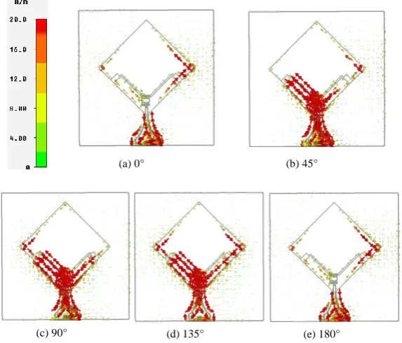
Figure 3 is the currents distribution of the antenna in different phase at 5.5 GHz. It illustrates the current distribution reaches the densest on the off-centered feed line and the edges of square slot. It can be observed on the ground plane, the direction of the current rotates clockwise with the phase from 0° to 180° in the RHCP mode, which is the characteristic of the RHCP wave.
Figure 3. Simulated surface current distribution in different phase at 5.5 GHz.
Results
As Figure 4 displays, Control voltage (high level of 3.3V) are input through the wire behind the proposed antenna. The BIAS pin of the SPDT switch is left open, and the GND port (the black wire) is grounded. A port connects with the white wire, and B port connects with the green wire.
(a) 0° (b) 45°
[image:4.595.155.442.273.518.2]Figure 4.The Photograph of the proposed antenna.
[image:5.595.68.531.291.458.2](a) (b)
Figure 5. The Simulated and measured results of the antenna in LHCP and RHCP modes: (a) S11; and (b) axial ratio.
(a)
(c)
(b)
[image:5.595.182.413.489.740.2]The simulated and measured reflection coefficient of the proposed antenna has been compared as illustrated in Figure 5 (a). It can be viewed the measured LHCP mode frequency band is 5.07-5.94 GHz, and the measured RHCP mode frequency band covers 5.10-6.04 GHz. The measurement matches well with the simulated results. Figure 5(b) shows the axial ratio results in the direction of maximum radiation. Compared with the simulation, the measured 3-dB AR bandwidth which are 5.03-5.87 GHz in LHCP mode and 5.06-5.91 GHz in RHCP mode become narrow. But with the error allowed, the antenna has achieved the 16.3% CP bandwidth.
Figure 6 presents the normalized radiation patterns for LHCP mode and RHCP mode in YZ-plane and XZ-plane. Due to the reason that the coordinates of the antenna plane and instrument are not coincide perfectly during testing, slight deviations can be observed between the simulation and measurement. Figure 7 is the measured gain of the antenna in different modes. The measured peak gain is about 3.69dBi at 5.5GHz in LHCP mode, and approximately 3.75dBi at 5.6GHz in RHCP mode. These two curves coincide with the measured return loss covers of the proposed antenna, which demonstrates the CP antenna has satisfactory performance in the pass band.
4.5 5.0 5.5 6.0 6.5
-3 -2 -1 0 1 2 3 4
Gai
n
(d
B
i)
[image:6.595.177.407.279.454.2]Frequency(GHz) LCHP RCHP
Figure 7. The measured peak gain of the proposed antenna in two modes.
Conclusion
A novel off-centered fed circular polarization reconfigurable antenna is proposed and designed in this paper. By choosing the state of the SPDT switch, this antenna can work in LHCP mode and RHCP mode with 16.3% 3-dB AR bandwidth, which can be applied to WLAN 5.2 GHz/5.8 GHz system. Due to the good performance of the switch and without complex DC network, good polarization reconfigurability is acquired viewed from the simulation and measurement.
References
[1] E. Doumanis, G. Goussetis, R. Dickie, R. Cahill, P. Baine, M. Bain, V. Fusco, J. A. Encinar, and G. Toso, Electronically Reconfigurable Liquid Crystal Based Mm-Wave Polarization Converter, IEEE Trans. Antennas Propagation. 62(4) (2014) 2302-2307.
[2] H. L. Zhu, S. W. Cheung, X. H. Liu, and T. I. Yuk, Design of Polarization Reconfigurable Antenna Using Metasurface, IEEE Trans. Antennas Propagation. 62 (6) (2014) 2898-2901.
[4] B. Kim, B. Pan, S. Nikolaou, Y. S. Kim, J. Papapolymerou, and M. M. Tentzeris, A Novel Single-Feed Circular Microstrip Antenna With Reconfigurable Polarization Capability, IEEE Trans. Antennas Propagation. 56 (3) (2008) 630–638.
[5] Y. Li, Z. J. Zhang, W. H. Chen, and Z. G. Feng, Polarization Reconfigurable Slot Antenna with a Novel Compact CPW-to-Slot line Transition for WLAN Application, IEEE Antennas Wireless Propagation Letters. (9) (2010) 252–255.
[6] P. Y. Qin, A. R. Weily, Y. J. Guo, and C. H. Liang, Polarization Reconfigurable U-Slot Patch Antenna, IEEE Antennas Wireless Propagation Letters. 58 (10) (2010) 3383–3388.
[7] J. S. Row, W. L. Liu, and T. R. Chen, Circular Polarization and Polarization Reconfigurable Designs for Annular Slot Antennas, IEEE Antennas Wireless Propagation Letters. 60 (12) (2012) 5998–6002.
[8] A. Khidre, K. F. Lee, F. Yang, and A. Z. Elsherbeni, Circular Polarization Reconfigurable Wideband E-Shaped Patch Antenna for Wireless Applications. IEEE Trans. Antennas Propagation. 61, (2) (2013) 960–964.
[9] X. L. Yang, J. C. Lin, G. Chen, and F.L. Kong, Frequency Reconfigurable Antenna for Wireless Communications Using GaAs FET Switch, IEEE Antennas Wireless Propagation Letters. 14 (2015) 807–810.
[10]W. M. Dorsey, A. I. Zaghloul, and M. G. Parent, Perturbed Square-Ring Slot Antenna with Reconfigurable Polarization, IEEE Antennas Wireless Propagation Letters. 8 (2009) 603–606.
[11]X. X. Yang, B. C. Shao, F. Yang, A. Z. Elsherbeni, and B. Gong, A Polarization Reconfigurable Patch Antenna With Loop Slots on the Ground Plane, IEEE Antennas Wireless Propagation Letters.. 11 (2012) 69–72.