2018 International Conference on Physics, Computing and Mathematical Modeling (PCMM 2018) ISBN: 978-1-60595-549-0
The Physical Layer Technologies in 5G
Mobile Communication System
Ping PEI
*and Yury N. PETRENKO
Belarusian National Technical University, Belarus
*Corresponding author
Keywords: Millimeter-wave, Massive MIMO, Mobile communication.5G wireless system.
Abstract. The continuously increasing demand of wireless communication impels the fast development of the next generation wireless communication technology. The fifth generation wireless mobile communication network (5G) has been proposed and is becoming a hot topic in academic and industrial field. Now, many countries or many corporations have completed the first step of 5G development which according to ITU requirements for future 5G. The 5G era is a high-speed network era of the interconnection of all things; it can load the many terminals access and high data transfer rate. However, the 5G communication technology which is scheduled to be commercialized around 2020 is still in its earlier stage. In order to solve the shortage of current radio waves resources and improve the capacity of system, two key technologies of physical layer (millimeter-wave and massive MIMO) were introduced and remarked. The best characteristics of millimeter wave technique are extremely-short wavelength and extremely-broad bandwidth. Its merits are narrow wave beam, good directivity and high antenna gain, the weakness is propagation on range of visibility. When these merits and weakness are applied to the 5G, it can solve many needs of 5G networks.
Introduction
Wireless mobile communication is a science which has the potential to grow. Recall from the first generation which support a small amount of analog voice signal to realize the video, audio, picture and other multimedia broadband services as (3G, LTE) only developed for decades. wireless communications technology is undergoing profound changes [1].
The demand for mobile communications have grown exponentially to compare with human beings. The emergence of 3G system, represents the wireless communications network from a purely technical system to provide a large number of multimedia data network system. 4G wireless communication technology has greatly improved in compare to 3G in spectral efficiency, transmission rate and system performance. However, there are still some problems about unable to meet the large-scale terminal access such as the shortage of wireless spectrum resources, end-to-end delay and the improvement of air interface utilization rate. The above problems prompted ITU, 3GPP, IEEE and equipment manufacturers to reflect on how about “the next generation of mobile communication system” Although 5G mobile communication system is in the stage of demonstration and experiment, however it has apparently become the hotspot topic in all over the world. For example, the European Union launched "5G NOW" research project in September 2012, Chinese government launched 5G "863" project in 2013 with setup IMT-2020 (5G) group, and the United States, South Korea, Japan have also found their own working group for 5G research [3]. These organizations implement on key technologies, frequency bands, and application scenarios in the 5G development direction. The goal in 5G communication system is to achieve a global internet which has high quality on reliability, low latency, and high data throughput. The new features of the future 5G mainly include:
Take Advantage of Higher Spectrum Resources
order to solve the problem which about current shortage of spectrum resources, the 30-300GHz spectrum resources will be used for the construction of the future 5G mobile communications [2].
Increase System Capacity and Enhance User Experience
Information technology bound to enter the era of big data with the continuous development of broadband wireless business. The number of mobile terminals will reach 50 billion [2] and the amount of data generated from different device will reach over a hundred times than now by estimated in 2020. These demands have prompted 5G mobile communication systems to increase system capacity for future societal development. However, the best user experience pursued by the user when the data transmission speed will reach the requirement of business and application. At this point, how a secure, real-time, stable wireless network environment to be established will become the dominant ideology of future network development.
System's Energy Consumption will be Reduced
The mobile communications will turn towards green communications in development. How to achieve the minimum energy consumption should be considered while meeting the growing number of businesses, quality of service and user experience [3].
Features of Millimeter Wave Communication
The development of mobile communication networks accompanied by the rise of key technologies from 1G to LTE era. At the same time, the key technologies meet business needs and promote the network function continues to developing. Similarly, the development of 5G can not be separated from support of key technologies [4]. This paper will introduce two kinds of 5G physical layer key technologies (Millimeter wave communication and Massive MIMO technology).
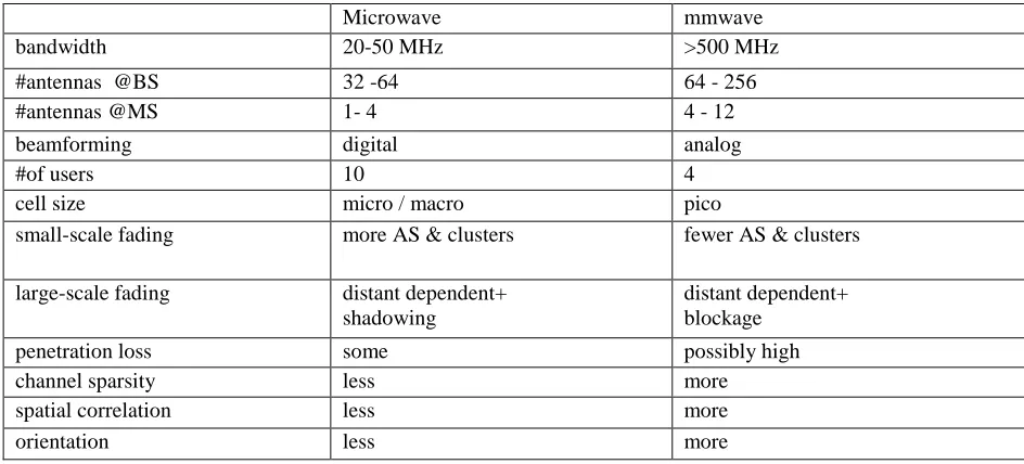
[image:2.595.61.533.583.797.2]Millimeter wave communication is a kind of microwave communication which length range of wave between 1 ~ 10 mm and radio frequency range between 30 ~ 300 GHz. Table I shows the characteristics of millimeter wave and microwave. The radio wave dissemination distance is a few kilometers when at 30GHz. But, if the radio frequency increase to 60GHz, dissemination distance only has 0.8 km. At the same time, millimeter wave is a very high frequency electromagnetic waves. Atmospheric absorption and rainfall decline has a great interference for millimeter wave propagation [5]. Why the telecommunication organizations still researching millimeter wave communication technology all over the world, because of the characteristic which millimeter wave has a short wavelength and propagation stability is higher than decimeter microwave is suitable for dense base station layout [6]. Currently, 5G millimeter wave technology still in phase of demonstrating and piloting time, the process of developing millimeter waves exist many problems should be considered.
Table 1. The characteristics of millimeter wave and microwave.
Microwave mmwave
bandwidth 20-50 MHz >500 MHz
#antennas @BS 32 -64 64 - 256
#antennas @MS 1- 4 4 - 12
beamforming digital analog
#of users 10 4
cell size micro / macro pico
small-scale fading more AS & clusters fewer AS & clusters
large-scale fading distant dependent+
shadowing
distant dependent+ blockage
penetration loss some possibly high
channel sparsity less more
spatial correlation less more
The Problem from Routing Path Loss in Propagation
Path loss is caused by the characteristics of channel [7]. The problem from path loss is a common phenomenon in all of wireless communication systems, signals easily to be interference during propagation from adjacent wireless channel. The model of propagation from radio wave path loss could expressed, as in
𝑃𝑡(dB) = 32.44 + 20lnd + 20lnf (1)
d in km and f in MHz. It can be found that the propagation path loss increasing as the radio wave frequency increasing, as in Eq. 1. Millimeter wave spectrum has greater pass loss in propagation to Compare with 300MHz-3GHz wireless mobile communication spectrum which used by LTE [7]. However, according to another 5G new techniques which named beamforming can concentrate energy in a small area to get a higher signal gain to solve the problem of path loss in propagation.
Signal Loss From a Building Penetration
The ability of low-band wireless signals in penetration is more powerful to compare with high- frequency. This is the reason why wireless signal will have much energy loss when penetrating the building [7]. As the millimeter wave has a large signal penetration loss and a short transmission in distance function, the signal can not enter the room for provide users communicate. However, by establishing millimeter-wave picocell nodes indoors could guarantee the communication quality very well.
Fading of Signals on a Rainy Day
The wireless communication needs to consider what are the different characteristics of signal in propagation with different frequency band range. At the same time, the fading of signals on a rainy day is an important factor in millimeter wave communication researching. Firstly, the length of wireless millimeter waves routing path propagation could be restricted by water molecules. Secondly, water molecules will reduce the reliability of wireless communication system [8]. The size of a raindrop mostly is the same as the length of millimeter wave. Therefore, it will cause serious disturbances to the millimeter-wave communication system when the rainfall is heavy. Here is a signal fading model of millimeter wave based on geographic observations which according to rainfall rate and rainfall structure [9], as in Eq. 2.3.
AR= aRb { eubd−1
ub } (0 ≤ D ≤ d) (2)
AR= aRb { eubd−1
ub − Bbecbd
cb + BbecbD
cb } (d ≤ D ≤ 22.5Km) (3)
The Advantages of Millimeter Wave Communication
A Millimeter Wave Occupies Large Bandwidth to Improve the Speed of Communication. It is generally considered that the frequency range of millimeter wave is between 26.5 to 300 GHz and the peak of bandwidth could arrive to 15 GHz. The peak rate is 5 times higher than the existing microwave transmission rate even with considering the problems which from atmospheric absorption or the fading of signals on a rainy day [9]. The research of millimeter wave propagation features become very popular in the frequency resource tense time.
A Millimeter Wave has a Narrow Beam. The millimeter wave beam is much narrower than the microwave beam at the same antenna size. For example, a 12cm antenna which working at 9.4GHz, the beam width is 18 degrees. However, if this antenna working at 94GHz, the beam width will become 1.8 degrees. Thus, a small target can be clearly distinguished from observation [10].
The Present Situation of Massive MIMO Technology Research
[image:4.595.193.404.258.362.2]MIMO technology has four-dimensional space (time domain, frequency domain, code domain, and airspace) which greatly improves the data transfer rate. MIMO technology not only evolved from 2×2 MIMO to 8×8 MIMO but also from single-user MIMO to cooperative MIMO with processor chip’s capacity enhancement. However, MIMO technology has been unable to meet the exponential growth of data for mobile broadband services and cloud computing [11] - [13]. Therefore, the researchers proposed Massive MIMO technology. The advances in MIMO technology developing include three aspects: firstly, from passive to active; Secondly, from two-dimensional (2D) to three-dimensional (3D); the last is from MIMO to massive MIMO arrays. Massive MIMO provides more orientation capabilities and beamforming capabilities [14]. The direction of the antenna diagram shown in Figure 1. Multi-dimensional massive MIMO technology will markedly increase spectral efficiency and reduce transmitting power to realizing green energy saving.
Figure 1. Millimeter Wave Directed Graph of massive MIMO system.
Channel Matrix of Massive MIMO and Application Scenarios
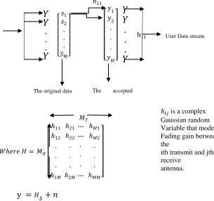
Processing huge amounts of data in transmission and acceptance simultaneously in massive MIMO system is able to the antenna matrix which with space multiplexing technology at base station side [15] - [16]. The system could provide services to more users to compare MIMO system, at the same time the working efficiency of the system has been improved [17]. Massive MIMO working principle model as shown in Figure 4:
ℎ11 | |
𝑌
𝑌
.
.
.
𝑌
[ 𝑠1 𝑠2 . . . 𝑆𝑀]
[ 𝑦1 𝑦2 . . . 𝑦𝑀]
| |
𝑌
𝑌
.
.
.
𝑌
h11 𝑀𝑇
𝑊ℎ𝑒𝑟𝑒 𝐻 = 𝑀𝑅
[ ℎ11 ℎ12 . . . ℎ1𝑀 ℎ21 ℎ22 . . . ℎ2𝑀 … … . . . … ℎ𝑀1 ℎ𝑀2 . . . ℎ𝑀𝑀]
y = 𝐻𝑆 + 𝑛
Figure 2. Channel Matrix of massive MIMO.
User Data stream
The original data The accepted
data
ℎ𝑖𝑗is a complex
Gaussian random Variable that models Fading gain between the
ith transmit and jth receive
[image:4.595.123.428.484.771.2]The Channel Status Information about Massive MIMO
With the number of antennas increasing in massive MIMO system, the base station needs to precisely gather current CSI (channel state information, CSI) to ensure the reliability of system communications [15] - [17]. The current research is based on time division duplex (TDD) for how to get an accurate channel state information. The TDD system effectively reduces the channel overhead, therefore the number of base station antennas are unrestricted. There are three types of interference factors during transmission in massive MIMO system, such as inter-cell, no coincidence frequency interference, and the interference which caused by pilot pollution [15]. Here have given equations which about massive MIMO system capacity in three kinds of interference factors [15], as in Eq. 4
C1 is the inter-cell interference as in Eq. 5, C2 is no coincidence frequency interference as in Eq. 6, C3 is the interference which caused by pilot pollution as in Eq. 7.
R = K (1 −QK
T ) ln (1 +
(M−1)OT2 1
pB+C1+C2+C3
) (4)
C1 = K − OT2 (5)
C2 = K ∑j>0 ( j2d2
d02 + 1)
−a2
− OT2∑l>0 ( l2d2Q2
d02 + 1)
−a
(6)
C3 = (M − 1)OT2∑l>0 ( j2d2
d02 + 1)
−a
(7)
Q is the pilot multiplexing factor, K is the number of terminal devices, M is the number of antennas on base station, OT2 is Estimated value of power. The equations about OT2 as in Eq. 8.
OT2 = {1 + ∑l>0 ( l2d2Q2{ d2
d02} + 1)
−a
2
+ 1
B0ptKQ } (8)
Multi-Cell TDD System's Channel Model in Massive MIMO
[image:5.595.178.418.615.746.2]In this moment, time division duplex (TDD) system has been assumed for massive MIMO model research [15]. The massive MIMO multi-cell TDD system channel model is shown in Figure 6. Supposing the number of cells is L, the number of antennas in sum is K, and the total number of base station antennas is M (M >> K) in this model. The pilot sequences of mobile terminals are orthogonal to each other in a same cell or between different cells. At this time, the sequence of orthogonal pilots’ length at least in K * L. The related events between each channel are very short when the terminal in a high-speed mobile environment [19]. Therefore, the channel parameters can not be accurately estimated if the pilot sequence is too long at this time [19].
Figure 3. The Model of massive MIMO multi-cell TDD system channel.
𝑔𝑙𝑗𝑚𝑘 = ℎ𝑙𝑗𝑚𝑘 ∗ √𝐵𝑙𝑗𝑘 𝑗, 𝑙 (9)
hljmk is fast fading coefficient which covariance is 1 and the mean of distribution is 0 in this
equation [17]. The physical size of antenna array which from the base station could be neglected between the distance calculation from mobile terminal to the base station [18]. Therefore, the slow fading coefficient can be expressed as in Eq.10
Bljk = zljk
dljky (10)
Summary
In recent years, mmWave communication is considered as one of the most promising technologies for both next generation cellular networks and High-Speed Tester (HST) communication systems, and in this paper, we have studied mmWave beamforming (BF) technologies for HSTs enabling to meet the growing demand for high-speed mobile Internet services in HSTs. Throughout the paper, we have introduced the BF schemes based on the beam pattern that we designed, and investigated three mmWave BF scenarios for HST communication [14]. Then, the simulation has been conducted to show the performance of the three BF scenarios. It is useful to recognize via the simulation that the different BF schemes are appropriate for different HST location and the fixed BF can achieve very similar performance to that of adaptive BF in most of time, which gave a valuable insight into designing the mmWave BF based HST communication system from feasibility and implementation perspective [20]. As future works, it is worth to study the performance of adaptive BF in the presence of calibration error and the HST communication system in various environments including the case of HST running along the curved line [21].
The large potential of massive MIMO systems as a key enabling technology for future beyond 4G cellular systems have been highlighted in this paper. The technology offers huge advantages in terms of energy efficiency, spectral efficiency, robustness and reliability. It allows for the use of low-cost hardware both at the base station as well as the mobile unit side. At the base station the use of expensive and powerful, but power-inefficient, hardware is replaced by massive use of parallel low-cost, low-power units that operate coherently together. There are still challenges ahead to realize the full potential of the technology [22]; for example, computational complexity, realization of distributed processing algorithms, and synchronization of the antenna units. This gives researchers both in academia and industry a goldmine of entirely new research problems to be tackled.
Acknowledgement
This research was supported by the Belarusian National Technical University department of information system and technologies.
References
[1]Z. Pi, F. Khan, “An introduction to millimeter wave mobile broadband system.” IEEE Communication Magazine., vol.49, no.6 pp. 101-107, 2011.
[2]A. Bleicher, “The 5G phones future.” IEEE Spectrum., vol.50, no.7, pp. 15-16, 2013.
[3]“Bell Labs: 5G urgent task is to be completed
as soon as possible standardization” (2015). [online]. Available:
http://www.xinhuanet.com/info/2015-03/11/ c_134058306.htm Accessed on: Jan.10.2018.
[5]T. S. Rappaport, S. Sun, and R. Mayzus. “Millimeter wave mobile communication for 5G cellular: it will work!” IEEE, no.1, pp. 335-349, 2013.
[6]Q. L. Zhao, J. Li, “Rain attenuation in millimeter wave ranges” Proceedings of 7th International Symposium on Antennas, Propagation & EM Theory. Guilin, pp. 1-4, 2006.
[7]H.Q. Ngo, T.L. Marzetta, and E.G. Larsson, “Analysis of the pilot contamination effect in very large multi-cell multiuser MIMO system for physical channel model.” IEEE International Conference on Acoustices. Speech and Signal Processing (ICASSP), Prague, pp.3464-3467, 2011.
[8]F. Rusek, D. Presson, and B.K. Lau, “Scaling up MIMO: opportunities and challenges with very
large arrays.” IEEE Signal Processing Magazine, vol. 30, no.1, pp. 40-60, 2013.
[9]H. Yin, D. Gesbert, and M. Filippou, “A coordinated approach to channel estimation in
large-scale multiple-antenna system.” IEEE Journal of selected Areas in Communications, vol.31, no.2, pp.264-273, 2013.
[10]Y. Li, Y.H. Nam, B. Ng, “A non-asymptotic throughput for massive MIMO cellular uplink with pilot reuse” IEEE Global Communications Conference (Globecom), Ottawa, pp.4500-4504, 2012.
[11]B. Gopalakrishnan, N. Jindal, “An analysis of pilot contamination on multi-user MIMO cellular system with many antennas” IEEE 12th International workshop on Signal Processing Advances in Wireless Communications (SPAWC), San Francisco, pp. 381-385, 2011.
[12]T. X. Vu, T. A. Vu, and T.Q.S. QUEK, “Successive pilot contamination elimination in
multi-antenna multi-cell networks.” IEEE Wireless Communication Letters, vol.3, no.6, pp. 617- 620, 2014.
[13]J. Zhang, B. Zhang, and S. Chen, “pilot contamination elimination for large-cale multiple-antenna aided OFDM system.” IEEE Journal of selected Topics in Signal Processing, vol.8, no.5, pp.759-772, 2014.
[14]N. A. Osama, T. Elpiniki, H. Howard. “Beamforming via large and dense antenna arrays above
a clutter.” IEEE Journal of selected Areas in Communications, pp. 314-324, Dec. 2013.
[15]F. Fernandes, A. Ashikhmin, and T. L. Marzetta, “Inter-cell interference in uncooperative TDD large scale antenna system.” IEEE Journal on Selected Area in Communication.vol.31, no.2, pp.192-201, 2013.
[16]V. Tarokh, N. Seshadri, and R. Calderbank, “Space-time codes for high data rate wireless communication: Performance criterion and code construction” IEEE Trans. Inf. Theory, vol.44, no.2, pp.744-765, 1998.
[17]J. Kermoal, L. Schumacher, K. Pederson, P. Mogensen, and F. Frederiksen, “A stochastic MIMO radio channel model with experimental validation.” IEEE Journal on Selected Areas in Communications, vol.20, no. 6, pp.1211-1226, 2002.
[18]S. Catreux, V. Erceg, D. Gesbert, and R. W. Heath, “Adaptive modulation and MIMO coding
for broadband wireless data networks.” IEEE Commun. Mag., vol.40, no. 6, pp. 108-115, 2002.
[19]K. Appaiah, A. Ashikhmin, and T. L. Marzetta, “pilot contamination reduction in multi-user TDD system.” IEEE International Conference on Communication (ICC), Cape Town, pp.1-5, 2010.
[20]H. Q. Spencer, B. Christian, and P. A. Lee, “an introduction to the multi-user MIMO downlink”. IEEE Communication Magazine, pp. 60-67, 2014.
[21]R.M. Rao, W. Zhu. “Multi-antenna test beds for research and education in wireless communication.” IEEE Communication Magazine, vol. 12, pp. 72-81, 2004.
[22]X.H. Wang, “Development and Application of Millimeter Wave Communication Technology”