2018 International Conference on Computer, Communication and Network Technology (CCNT 2018) ISBN: 978-1-60595-561-2
The Analysis and Application of Testability Development
Test for Equipment
Kun-ye ZHOU, Tao JIANG
*and Ning ZHANG
Naval University of Engineering, Wuhan, China
*Corresponding author
Keywords: Development test, Sample size, Testability.
Abstract. The newly issued national military standard, ‘Material testability test and evaluation’, has made a clear definition and introduction to the development test of equipment. However, there is still a lack of systematic discussion about how to carry out the test work at present. Therefore, based on the current engineering of aeronautical equipment, an essential method of the development test is put forward, and then the key link in the development test is analyzed, which is to formulate the development test scheme. Finally, through the case of a transmitter receiver, the validity and maneuverability of the method are verified, providing a good reference for the development of the equipment in the future.
Introduction
The newly issued GJB 8895-2017 ‘Material testability test and evaluation’ provides effective theoretical guidance for the testability verification of equipment. In the design phase, by means of failure injection the designer can measure whether the testability design meets the requirements, fully exposes the design defects and improves the scheme, so as to achieve the improvement of the equipment [1].
At present, the research on testing and verification engineering of equipment mainly includes: In view of the characteristics of "small, multi stage, and different population" of experimental data of testability growth in the development stage, Liu Lei lead to the problem that the test level is difficult to verify and evaluate and an optimized dynamic Bayes method is proposed [2]. Chen Ran proposed a fault simulation method based on the signal model to realize the reappearance of the fault. It can effectively excavate the potential of the existing fault injection means and greatly increase the amount of the effective injection of the fault samples [3]. By analyzing the relevant standards of testing verification at home and abroad, Shi Junyou summed up the shortcomings of its applicability, and proposed to establish a test verification special standard to guide the test verification work [4]. In conclusion, there is still a lack of systematic discussion on how to carry out testability development test. Therefore, it is worth studying and discussing.
Work Flow of Testability Development Test
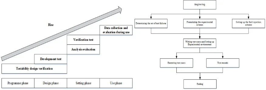
The test verification and evaluation engineering is clearly divided into 5 projects, including: testability design verification, development test, verification test, analysis evaluation, and data collection and evaluation during use. Among them, test development test refers to the process of fault injection or simulation test, analysis and improvement carried out by the contractor in the semi physical model of the product, the prototype, or the test part to confirm the test design characteristics of the product. The relationship between testability testing and evaluation items is shown in Fig. 1. As the core link of the testability testing and evaluation, the development test can evaluate the existing fault diagnosis ability before the product is transferred to the setting phase, and it is of great significance to the improvement of the testability design.
1) Determining the set of test failures 2) Formulating the experimental scheme 3) Setting up a fault injection scheme
4) Writing test cases and setting up experimental environment 5) Executing test cases
[image:2.612.89.527.150.299.2]6) Test records
Figure 1. Relationship between testability test and evaluation. Figure 2. Work flow of testability development test.
The core of testability development test is to formulate the experimental scheme. The main work of the test scheme includes the determination of the sample size, the distribution of fault samples, the selection of the index evaluation, which will directly affect the feasibility, cost and accuracy of the test evaluation conclusion.
Formulating the Experimental Scheme
The experimental scheme of the product is affected by the factors including the requirement of the test, risk, cost, and so on, which is based on the statistical theory [5-6].
Determination of the Sample Size
In the development test, the common test statistics include the fixed number test scheme, the minimum acceptable value test scheme, the truncated sequential test scheme and the Bayesian based parameter estimation scheme [7-9].
The test plan is applicable to both the ordering party and the contractor to agree on the testability indicators. Usually, the ordering party and the contractor will agree on the testability index of the product. For example, the ordering party requires that the equipment failure detection rate is generally not lower than the limit quality level q1 (the minimum acceptable value). When the actual fault detection rate q is less than the limit quality level q1, the product will be rejected. In order to make the real value of the fault detection rate satisfy q > q1, the design requirement of the fault detection rate is required to satisfy q0 > q1, so that the product can be received with a larger probability.
Considering one-time test process (n, c) of the fault detection rate, n is the number of test times (the
sample size), and the c is the maximum allowable number of test failures (the number of qualified
judges). At the moment, if q < q1, the product should be rejected by the subscriber. However, due to
the randomness of the sampling, the probability of the actual failure number F < C is as Eq. 1 shows:
( )
n-1 1
0
( c)
c n i i i
P P F q
=
= ≤ =
∑
(1) The probability value P1is called the subscriber's risk, which is recorded as β.
minimum acceptable value q1 and the subscriber risk β will be given, and the sample size is
determined by Eq. 2.
(
)
1 1 1 0 1 β − = − ≤ ∑
c n ni
n
q q
i
(2) The available test schemes determined by this method have infinitely many groups, and the suitable test scheme can be determined according to the required lookup table. The general sample size n is
greater than the minimum value of the total number N0 in the product failure mode.
Distribution and Supplement of Fault Sample
After determining the sample size of the test, it is necessary to extract the corresponding number of fault modes from the failure mode of the product to form the fault sample set. The simple proportional random sampling method or the sampling method based on the failure rate could be adopted [10-11]. The simple random sampling method is based on the cumulative range determined by the relative frequency of the fault samples according to the relative frequency of the fault samples. The random number from 0 to 99 uniformly distributed random numbers is extracted randomly in the whole sample, and the initial sample size N1is obtained. For example, the failure mode of a receiver, the relative frequency ratio and the cumulative range of faults are shown in Table 1.
Table 1.Random sampling results of a certain receiver.
No. Unit Failure Mode Fault Relative Frequency Ci Range Sample Size 1
Receiver
Parameter drift Component 0.20 00~19 3
2 Short circuit or open circuit 0.35 20~54 8
3 Harmonization failure 0.45 55~99 9
Total 1 20
λ λ
=∑ i i i i
i i i
Q T C Q T (3) = i i n nC (4) 1 0 = =
∑
n i i N n (5) In the form: Qi is the number of the i unit, λi is the failure rate of the i unit, Tiis the working time coefficient of the i unit (equal to the ratio of the working time to the full working time of thecomponent).
After the end of the sample allocation, the sample size of the unallocated samples is added to verify FCR (Fault Coverage Rate). The sample size supplement in the testability test is: one sample size will be added to the failure mode which is not allocated to the sample size and by means of BIT (Built-in Test). In order to control the workload of the trial, on the basis of the initial sample size of N1, the
maximum number of samples required for supplementary sample size is generally N2.
Assuming maximum upper limit of test is N2, and N2 > N0:
1) If N1≤ N2,at the end of the initial sample allocation, samples are added to the fault pattern that is
not allocated to the sample size, and the sample size for each failure mode is one.
Selection of the Index Evaluation
In terms of FDR (Fault Detection Rate) and FIR (Fault Isolation Rate), the calculation points can be estimated according to the experimental data, and the two terms distribution method is used to estimate the limit value of the unilateral confidence or the confidence interval value [12].
The point estimates of BIT and ATE (Automatic test equipment) are shown in Eq. 6
ˆ ρ=n−F
n (6)
For the FDR, n represents the number of fault samples; F represents the number of undetected
faults. For the FIR, n represents the number of successfully isolated faults; F represents the number of
unsuccessfully isolated faults.
The FDR of BIT and ATE is evaluated by one side confidence lower limit, shown in Eq. 7.
(
)
0
1 1 −
=
− = −
∑
F n i iL L i
n
R R C
i
(7) In the equation, n is the sample size, and F is the number of failure detection or successful isolation
of the tested products. It can be obtained by statistics at the end of the test implementation; C is the
reliability, generally takes C=0.8, and RL is the single side confidence lower limit evaluation value of
the FDR.
Case Application
Basic Information
[image:4.612.83.528.451.527.2]The transmitter receiver of a certain type radaris a system level product, consisting of 5 LRU (Line Replaceable Unit). The list and quantity of the composition are shown in Table 2.
Table 2.The component of a certain type radar.
System LRU Number
Transmitter receiver
Transmitter 1
Amplifier 1
Receiver 1
Modulator 1
Power Supply 1
Sampling Situation
According to the FMECA (Failure Mode Effects and Critical Analysis), 47 SRU (Shop Replaceable Unit) level failure modes are selected. When β=0.2 and q1=0.9, the minimum acceptable value test scheme is 54.
After the allocation of sample size, 27 sample sizes were added to 31 unallocated sample failure modes, and 81 alternative fault samples were set up for the alternative sample library.
Test Result
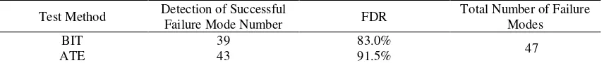
Table 3. Evaluation index of FDR.
Test Method Detection of Successful
Failure Mode Number FDR
Total Number of Failure Modes
BIT 39 83.0%
47
[image:4.612.94.522.686.731.2]The results of the test are shown in Table 3-4. Suggestions for design improvement are made for the problems exposed during the testability test.
1) Suggest iterative modification of FMECA;
2) Modify the BIT software testing and diagnosis strategy against BIT failure;
[image:5.612.89.526.168.239.2]3) Improve the detection logic and diagnosis strategy of the fault diagnosis unit in view of the fact that the special test equipment is not reported.
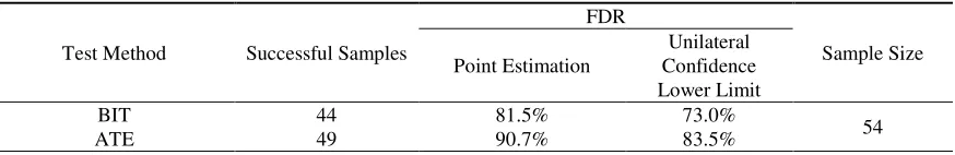
Table 4. Evaluation index of FDR.
Test Method Successful Samples
FDR
Sample Size Point Estimation
Unilateral Confidence Lower Limit
BIT 44 81.5% 73.0%
54
ATE 49 90.7% 83.5%
Summary
1) According to the testability engineering and requirements of the national military standard, the method of testability development test is put forward.
2) The core of the development test is the formulation of the statistical scheme, including the determination of sample size, the distribution and supplement of sample size, and the selection of index evaluation.
3) As the key link of the test verification technology, the test development test is of great significance for the equipment to improve the fault diagnosis ability and to find the test design defects.
References
[1]Zhao C X.Research on testability growth test theory and method[D].Changsha: National University of Defense Technology, 2016.
[2]Liu L, Song J Y, Yao M.Testability verification and evaluation method based on dynamic Bayes theory in development stage[J].Computer Engineer and Design:2017, 38(6):1516-1521.
[3]Chen R, Lian G Y, Qin Z L, et al. Fault injection approach for line replaceable module based on hierarchical model[J]. Journal of Zhejiang University (Engineering Science) 2017, 51(7):1390-1396.
[4]Shi J Y, Ji C, Li H W. Analysis of Testability Verification Technology and Application Status[J]. Measurement & Control Technology, 2012, 31(5):29-44.
[5]Qiu J, Liu G J, Zhang Y, et al.Test and evaluation technology of equipment testability[M]. Beijing:Science Press, 2017:1-17.
[6]Min T Y, Jiang L, Liu L, Application of testability modeling and testability verification test[J].Avionics Technology, 2016, 47(1):41-46.
[7]Chen R, Liang Y, Zhang X S, et al. Methods of experiment sample size determination based on fault injection experiment[J]. Computer Measurement & Control,2015, 23(12):3994-3997.
[8]Zhang X S, Huang K L, Yan P C, et al. Method of confirming testability verification test schemebased on prior information[J]. Journal of Beijing University of Aeronautics and Astronautics, 2017, 41(8):1505-1512.
[9]Yu C, Wang X H, Li Q. Q. Calculation and selection of sequentially truncated test scheme[J].Journal of Beijing University of Aeronautics and Astronautics, 2014, 40(4):574-578.
[11]Li T M, Qiu J, Liu G J, et al. Allocation plan of failure samples based on failure rate in testability[J].Acta Aeronautica et Astronautica Sinica, 2009.30(9):1662-1665.