© 2016, IRJET | Impact Factor value: 4.45 | ISO 9001:2008 Certified Journal | Page 63
DESIGN AND DEVELOPMENT OF A GROUNDNUT DECORTICATING AND
SEPARATING MACHINE.
C. C. Eze - Department of Mechanical Engineering, Michael Okpara University of Agriculture,
Umudike, Abia State, Nigeria.
Abstract :
An integrated groundnut decorticating and winnowing machine which bears a 1 Ihp, 1000 r.p.m. electric motor was designed and developed. It is a 1000mm x 400mm x300 mm machine of gross mass 33.42kg which makes it portable. Falling pods from the hopper are struck by a rotating dehusking drum of 72.2 N force, the chaffs are blown out through a window and the seeds fall down and out via a chute. All the components of this machine were sourced locally making the overall cost cheap and affordable to the people in contrast with the decorticators imported from overseas.KEYWORDS
:
Groundnut, decorticator, blower, locally-sourced materials, affordable.1.0
INTRODUCTION
Groundnut or peanut or earthnut (Arachis hypogaea) is one of the most important food legumes in the world (1). It has been identified as one of the leguminous species with the greatest potential for both food and industrial purposes in the tropical regions of Africa. This crop is a major source of income to the people in the major producing states of the federation and is a major source of revenue for rural and other capital development projects in such states. The production rate world-wide is over 270,000 metric tonne annually (2). Nigeria possesses a land area of 923,768 Km2 of arable land i.e. about 91 million hectares of land, and vegetation ranging from the Sahel savanna in the extreme North to Swamp forest in the South. Of this, over 85 million hectares is uncultivated land, about 82 million hectares has the potentials for agriculture, and groundnut can thrive very well in all the states of Nigeria (3). Even with this little cultivated portion (6 million hectares or 55,500km2 or 5.1%), Nigeria is ranked 4th in the world in the production of groundnut with over 1.55 metric ton in 2012 (2).
Nigeria, though the fourth highest producer of groundnut in the world still finds it hard in processing this oil seed in the area of dehusking. A good percentage of the farmers of this crop crack the pods using fingers and stones or by beating out the seeds with paddles and sticks. This is time wasting, boring and energy sapping. Other producers and marketers of this economically important crop who procure decorticating machines from overseas do this with tears because the stresses and costs involved in importation is enormous. Some imported large-scale plants are increasingly replacing small groundnut processing units, but due to high foreign exchange rate, the cost of such imported machines is clearly out of reach of poor farmers in Nigeria. Developing an affordable groundnut decorticator to ease the labour associated with shelling and reduce operational cost and time would enable the high potentials of the crop to be harnessed optimally.
© 2016, IRJET | Impact Factor value: 4.45 | ISO 9001:2008 Certified Journal | Page 64
materials, which is cheap and affordable to the majority of the farmers and processors of groundnut to encourage the cultivation of this important food crop.
2.0
METHODS AND MATERIALS
2.1 Description of the groundnut Sheller
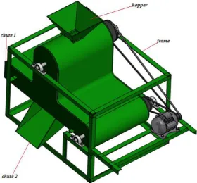
In this design, the shelling machine consists of the following basic units: the frame, hopper, shelling, winnowing and delivery units.
The frame carries the entire components of the machine. It was constructed from 50mm by 50 mm angle mild-steel iron.
The hopper feeds the groundnut pods to be decorticated into the shelling unit, the pods falling down the shelling unit by gravity. The hopper is square shaped with the inlet side frames tilted 60o to the horizontal to prevent falling out of pods during decorticating. The neck base of this hopper which leads into the shelling unit is square, 58 by 58 mm2 and can only let a maximum of 86 pods into the decorticating or shelling cylinder per unit time.
The decorticator drum is a cylinder formed with 6 mm diameter spiral aluminium rods with the spiral edges forming the shelling spikes. It bears two circular mild-steel plates of thickness 3.5 mm and 200 mm diameters, which were drilled through at the centre to hold the 14 mm diameter decorticator shaft in position with the end bearings.
Decortication is effected when the falling pods from the hopper hit the rotating spikes of the aluminium rods that form the cylinder drum. The nuts and chaffs by machine vibrations fall through a semi-circular sheet metal sieve of 10 mm diameter slots, fixed just under the rotating decorticator. The groundnut shells are separated from the seeds by an air stream supplied by a blower as both materials fall towards the delivery pan. The chaffs are blown out through chute 1 while the seeds fall down and out through chute 2. Undecorticated pods cannot pass through the 10 mm diameter holes of the sheet metal sieve and are swept out after decortication operations.
© 2016, IRJET | Impact Factor value: 4.45 | ISO 9001:2008 Certified Journal | Page 65
Figures 1- The shelling components of the machine
© 2016, IRJET | Impact Factor value: 4.45 | ISO 9001:2008 Certified Journal | Page 66
Figure 3-The wire view of the integrated machine
Figure 4 - The integrated decorticating and separating machine.
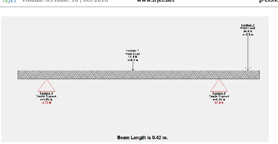
Using the Beamboy software, the relevant reactions and moments were obtained: Vertical load components of the decorticator belt = T1sin12o + T2sin12o
[image:4.595.80.361.425.685.2]© 2016, IRJET | Impact Factor value: 4.45 | ISO 9001:2008 Certified Journal | Page 67
3.0 DESIGN ANALYSIS AND CALCULATIONS
Some ground nuts were stochastically collected from a basket of the dry nuts using small plate and weighed.
2.1.1 Weight of a dry undecorticated groundnut
.Average mass of one dry groundnut nut was obtained using this expression, Am=
(
)
2 1 3
p
p
p
(1)where, number found in the plate = p2 =67 nuts
Mass of both plate and contents = p3 = 62.65g
Mass of empty plate = p1 = 13.43g.
2.1.2. Breaking force dry groundnut pod using a falling mass
Mass of falling body = 400g = 0.4kg
Average force required to break one pod (without crushing the seeds) may be obtained thus:
Employing Newton’s law of linear motion s = ut +
2
1
gt 2 (2)
or g =
2
2t
s
if the initial velocity u = 0 (3)
where t and s = time taken to hit the ground and height of fall respectively, and g = gravitational acceleration.
Thus for a mass (m) of 400g to take the time t = 0.8 seconds to fall freely from a height s = 0.75metres to hit the nut, the
force generated by the falling body (from 2 and 3), to decorticate one pod, the force F = mg
F =2
2t
ms
(4)
The diameters of the motor and decorticator sheaves according to (4) are related to their revolutionary speeds as
2 1
n
n
1 2d
d
(5)Where n1 = motor sheave speed = 1000rpm
n2 = decorticator drum sheave speed = 200rpm
d1 = motor sheave diameter =40mm = 0.04 m; r1 = 0.02 m
© 2016, IRJET | Impact Factor value: 4.45 | ISO 9001:2008 Certified Journal | Page 68
From equation (5), d2 =
2 1 1
n
d
n
(6)
2.1.3. Hopper dimensions
Area of square hopper neck from this expression Ah = l2, (7)
l being the length, 38 mm and breadth, 38 mm of hopper
Estimated surface area of one undecorticated dry groundnut pod (obtained by the expression of assuming areas of two small circular objects, each of diameter 5 mm stuck together)
Ag = 2πr2 (8)
:. Estimate maximum pods that can go through the hopper neck per unit time Nh = g h
A
A
= (9).
Also, mass of maximum pods in decorticator per unit time mp= Nh x Am (10)
The total force required to decorticate this maximum number of pods that may from time to time go through the hopper neck into the decorticator drum per unit time was considered as
FT = F x Nh (11)
2.1.4 Decorticator drum
This drum was fabricated of 0.7mm spiral aluminium rods. The spiral edges form the cracking spikes.
Length of decorticator cylinder = 200 mm
Diameter of decorticator drum = 200 mm; radius = 100 mm
Mass of decorticator drum (measured without groundnut pods) = 1100 g
2.1.5. Force possessed by revolving decorticator
The centrifugal force possessed by the spiral spikes of the decorticator rods Fc =
r
mv
2(12)
where m = mass of decorticator drum + mass of maximum number of groundnut pods in it
v = linear velocity of spikes on drum since decorticator pulley speed n2 = 200rpm
and v = ωr,
v =60
2
n
2r
(13)© 2016, IRJET | Impact Factor value: 4.45 | ISO 9001:2008 Certified Journal | Page 69
:. Force possessed by the decorticator spikes, the centrifugal force from equation (12) = Fc
To minimize energy waste, the force possessed by the revolving decorticator should just be slightly higher than the force required to decorticate the maximum number of pods that may possibly get into the decorticator drum per unit time.
2.1.6 Torque possessed by decorticator spikes Td
Td = mαr (14)
Where mass of decorticator drum + maximum number groundnut pods = mT
α = tangential component of the angular acceleration of the decorticator drum
=
r
mv
2, (normal/centripetal components being zero). (15)
Radius of decorticator drum + height of spikes = r
:.Torque Td from equation (16) = r x
r
mv
2(16)
2.1.7. Motor power requirement
This involves
(i) Power required to drive the decorticator. The power required to drive the decorticator Pd = Td . ω (17)
where ω is the angular velocity of decorticator drum =
60
2
N
(18)
(ii) Power required to drive the blower
The power consumption of a blower which is the function of the power required to run it can be calculated using equation (19), according to (5), which is derived from adiabatic compression equation. This was modified by (6) as
(19) Here, the following particulars apply for the blower chosen
: Motor efficiency (0.76 )
: Blower efficiency (0.78 )
: Inlet pressure, absolute ( 0.3kpa )
© 2016, IRJET | Impact Factor value: 4.45 | ISO 9001:2008 Certified Journal | Page 70
: Power (kW)
: Air flow in ambient condition (7m3/min)
:. The power requirement of the blower bears the symbol Pw as in equation (19). Therefore, the total power required by the motor to run the machine should be a little above that required by both the decorticator and blower sections ie (Pd +
Pw) watts. An overload factor of 1.23, was used to obtain the total power PT = 1.23(Pd + Pw) watts (20)
2.1.8 Motor torque
The motor torque involved in the drive may be obtained using this expression (7)
Tm = PT x 1
554
.
9
n
(21)2.1.9 Tensions in the V-belt drive of decorticator shaft
The relationship existing between the two tensions in a V-belt arrangement according to (8) is
2.3 log
(
)
2 1
T
T
= µθcosecβ (22)
Where T1 = tension on the tight side of the belt
T2 = tension on the slack side of the belt
x = centre distance between the two shafts = 350mm = 0.350m.
r2 = decorticator sheave diameter
r1 = motor sheave diameter
. α = angle of wrap = x + sin-1
(
2 1)
x
r
r
(23)µ = coefficient of friction between the belt and groove side = 0.5123 (8)
θ = angle of contact on the motor sheave, and Now θ = 180o - 2α x
)
180
(
(24)β = half of the groove angle of the sheaves, where the full angle of groove is measured as 32o.. Thus β=
)
2
32
(
o
= 16o
From equation (14),
(
)
2 1
T
T
= log-1
)
3
.
2
cosec
µ
© 2016, IRJET | Impact Factor value: 4.45 | ISO 9001:2008 Certified Journal | Page 71
Again, the power transmitted by this v-belt is related to tensions in this expression (8)
PT = (T1-T2)Vb . , (26)
Where PT = motor power and Vb = belt velocity which is given as Vb =
)
60
(
d
1n
1 (27)2.1.10 Decorticator shaft diameter
The shaft is made of steel having a yield stress of 240 Mpa. ASME code was used to design the diameter of the shaft for suddenly applied load with combined fatigue and shock factors in bending and torsion. Subsequently, the bending and twisting factors are kb = 2.0 and kt = 1.5 respectively. The diameter of the shaft may therefore be determined using maximum shear stress theory (4)
d3 =
(
16
)
max
(Mb.kt)2 + (Mt.kt)2where d = shaft diameter
τmax = permissible shear stress = 0.3 of the material yield stress or 0.3Syt (9)
= 0.3 x 240 = 72 Mpa
Mb = maximum resultant bending moment = 10.23 Nm
Mt = maximum working stress in shear = 14.95 Nm (equation 16).
Kb = combined shock and fatigue factor for bending moment = 2.0
Kt = combined shock and fatigue factor for torsion =1.5
= 3
max
.
).
16
(
d
= (Mb x kb) + (Mt x kt)
d3 =)
© 2016, IRJET | Impact Factor value: 4.45 | ISO 9001:2008 Certified Journal | Page 72
4.0RESULTS AND DISCUSSIONS
[image:10.595.31.483.176.437.2]4.1 Results
Table 1- The preliminary parameters/calculations leading to the machine design.
s/n Preliminary parameters symbol value Unit
1 Average mass of one dry groundnut pod Am 0.77 G 2 Force required to decorticate one dry groundnut pod F 0.94 N 3 Decorticator drum sheave diameter d2 200 Mm 4 Maximum number of pods through hopper per unit time Nh 86 pods 5 Mass of maximum pods in decorticator per unit time Mp 66.22 G 6 Total force required to decorticate all pods per unit time FT 80.63 N 7 Mass of decorticator drum (without pods) Md 1100 G 8 Mass of aluminum sheave attached to the decorticator shaft Ms 183.5 G
9 Mass of belt Ml 40 G
10 Centrifugal force of decorticating spikes Fc 81.14 N 11 Linear velocity of spike regions v 3.19 m/s 12 Angular velocity of spike regions 20.95 rad/s 13 Torque possessed by decorticator spikes Td 14.95 Nm
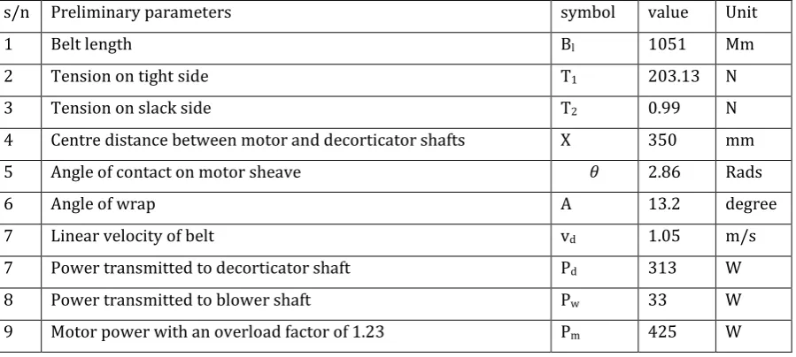
Table 2- Belt and motor calculated parameters
s/n Preliminary parameters symbol value Unit
1 Belt length Bl 1051 Mm
2 Tension on tight side T1 203.13 N
3 Tension on slack side T2 0.99 N
4 Centre distance between motor and decorticator shafts X 350 mm
5 Angle of contact on motor sheave 2.86 Rads
6 Angle of wrap Α 13.2 degree
7 Linear velocity of belt vd 1.05 m/s
[image:10.595.34.484.487.689.2]© 2016, IRJET | Impact Factor value: 4.45 | ISO 9001:2008 Certified Journal | Page 73
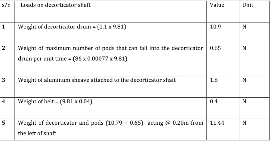
Table 3- Total load on decorticator shaft`
s/n Loads on decorticator shaft Value Unit
1 Weight of decorticator drum = (1.1 x 9.81) 10.9 N
2 Weight of maximum number of pods that can fall into the decorticator drum per unit time = (86 x 0.00077 x 9.81)
0.65 N
3 Weight of aluminum sheave attached to the decorticator shaft 1.8 N
4 Weight of belt = (9.81 x 0.04) 0.4 N
5 Weight of decorticator and pods (10.79 + 0.65) acting @ 0.20m from the left of shaft
11.44 N
Table 4-Vertical and horizontal load components on the decorticator shaft.
s/n load components of the belt Value Unit
1
Vertical load components of the belt (T1sin12o + T2sin12o)
42.44 N
2 Weight of pulley and belt (1.8 + 0.4) 2.2 N
3 Vertical load effect at sheave side (42.44 + 2.2) N acting @ 0.4m from left. 44.64 N 4 Total vertical force Vl (11.44)N + (44.64)N 56.53 N
5 Reaction supports at 0.05m for A and at 0.35 for B, both from the left. -1.72, 57.8 N 5 Total moment arising from vertical load on shaft Mv 2.23 Nm 6 Horizontal forces R1H + R2H = (T1cos12o + T2cos12o ) 199.6 N 7 Total moment arising from horizontal load on shaft Mh 9.98 Nm 8 The resultant maximum bending moment Mb = (Mv)2 +(Mh)2 or
(2.23)2 + (9.98)2 Mb
10.23 Nm
ss9 Maximum working stress in shear Mt 14.95s Nm
10 Standard decorticator shaft diameter was selected 14 Mm 11
The horizontal reaction components, RAH and RBH
[image:11.595.38.516.405.696.2]© 2016, IRJET | Impact Factor value: 4.45 | ISO 9001:2008 Certified Journal | Page 74
Figure 3- The decorticator free body diagram with vertical stresses
[image:12.595.37.262.403.564.2]© 2016, IRJET | Impact Factor value: 4.45 | ISO 9001:2008 Certified Journal | Page 75
[image:13.595.37.264.413.558.2]Figure 4 - The decorticator free body diagram with horizontal stresses
Table 6 - Maximum values of horizontal stresses on decorticator shaft.
4.2 Discussions
In Table 1, the preliminary parameters and calculations leading to the machine design were obtained. The total force needed to decorticate the maximum pods per unit time in the shelling unit is 80.63 N, and the force possessed by the sheller spikes is 81.14 N indicating that decortication is possible. From the motor horsepower standards of Engineering tool bar (7), a 1 horsepower, 1000 rpm motor was chosen as adequate.
© 2016, IRJET | Impact Factor value: 4.45 | ISO 9001:2008 Certified Journal | Page 76
Table 3 shows the various loads on the decorticator shaft. The total weights of decorticator and pods is 11.44 N, acting at 0.20m from the left of shaft; that of the belt is 0.4 N.
Table 4 is the vertical and horizontal load components on the decorticator shaft. The total vertical force component is 56.33 N, while that of the horizontal is 199.6 N. The total vertical moment and horizontal torsional stress are 2.23 and 9.98 Nm respectively. The decorticator shaft experiences a maximum bending moment and stress in shear of 10.23 and 14.95 Nm respectively. Based on these stress values involved in the machine operation, a standard decorticator shaft diameter of 14 mm was selected.
Tables 5 and 6 show the maximum stress values on the decorticator shaft as a result of vertical and horizontal loads acting on it respectively, including the locations on the shaft where they act.
5. CONCLUSION
A simple groundnut decorticating and separating machine is designed and developed. It is portable and simple to operate. Every component of the machine was sourced locally thus giving a machine that is cheaper than the costly and complex imported heavy groundnut decorticators which are usually out of the reach of the common farmers and the local entrepreneurs.
REFERENCES
[1] Norde, E.N.; Jensen, C. and Helsel J.D. (1982): Priorities and strategies for groundnut research in Nigeria. National workshop on Groundnuts. Institute for Agricultural Research, Samaru. Ahmadu Bello University, Zaria-Nigeria. p.34.
(2) United Sates Department of Agriculture (USDA, 2009): U.S. Department of Agriculture (2009).Data on Groundnut Oil. http://www.nal.usda.gov/fnic/foodcomp/search/. Retrieved on April 22, 2016.
(3) Sambo, A.S. (2007).Renewable Energy Development in Nigeria: A Situation Report In Proceeding of the International Workshop on Renewable Energy in Africa, July 30th to August 1st, University of Nigeria, Nsukka,1-39.
(4) Joseph, S., Charles, R. M.., Richard, G. B., Keith, J. N. (2008): Mechanical Engineering Design: Tata McGraw-Hill Publishing Company Limited, New Delhi.
(5) Blower-online MBR info-www.onlinembr.info/cost/blower. htm. Retrieved on 15/3/2015
[6] Burton. [2002].
Blower power calculation
-http://onlinembr.info/cost/blower-power-calculation. Retrieved on 03/04 15(7) Engineeringtoolbar: Fan efficiency and power consumption: www.engineeringtoolbar.com/fans-efficiency-_Power_consumption. Retrieved on 14/11/2016.