© 2016, IRJET | Impact Factor value: 4.45 | ISO 9001:2008 Certified Journal
| Page 2482
Optimal Placement of Capacitor and DG for Minimization of Power
Losses using Genetic Algorithm and Artificial Bee Colony Algorithm
Aakanksha Kumawat
1, Pushpendra Singh
21
Student, Department of Electrical and Electronics,Government Women Engineering College, Ajmer,Rajasthan,
India
2
Assistant professor, Department of Electrical and Electronics, Government Women Engineering College Ajmer,
Rajasthan, India
Abstract: This paper speaks to a viable strategy for ideal situation of DG and capacitor in dispersion framework. The
primary goal is to lessen the power losses in the test system by setting capacitor and DG of ideal size and at ideal area. Conveyance system associate the high voltage transmission system and low voltage side, subsequently it is important to keep the system at least misfortunes for making our system sound. Position of capacitor enhances the voltage profile and lessens the power losses and vitality losses in influence system. Capacitor situation works for reactive power compensation. This paper contains the subsequent graphs for capacitor and generator positions in the test system, the graphs will demonstrate the relative consequences of power losses. Newton-Raphson technique under burden stream study is utilized to figure out the active and reactive losses in the system and relative investigation of Genetic algorithm and ABC is utilized to check the outcomes additionally by utilizing genetic algorithm toolbox as a part of MATLAB programming we get the size and location of capacitor and DG in test system. Genetic algorithm and ABC are the advancement methods utilized here to locate the viable, proficient and best location and size of capacitor and DG by utilizing these advancement systems. IEEE 33 and 69 bus test systems are utilized to confirm the proficiency of these calculations.Key words-Capacitor placement, DG placement, ABC algorithm, Genetic algorithm, Distribution System, load flow, power
system
1.
INTRODUCTION
Distribution generation is the units set close to the heap it serves. These are essentially little scale generators that creates a few KW to several MW of power. They might possibly be joined with the network. DG units are numerous sorts of generation techniques for instance biomass, gas turbine, wind turbine, sun powered voltaic and diesel motors. DG is otherwise called inserted generation, on location generation, decentralized generation. DG gathers vitality from distinctive different sources and consequently Enhances security of supply, additionally the association of DG to network expands the steadiness of power system [1]. Numerous methodologies have been proposed to unravel DG estimating and position in distribution system. Ayse Aybike Seker and Mehmet Hakan Hocaoglu used ABC algorithm on 33, 69, 229 bus radial test systems In solving non linear optimization problems and successfully shows that ABC can successfully determines optimal place and size of DG unit[1]. Dharani Hemanath kumar, P suresh babu, M padma Lalitha perform ABC algorithm on 33 bus test system,in their results they shown that ABC for real power loss minimization is the most effective and efficient technique[2]. Mahdi Mozaffari legha, Marjan Tavakoli, Farzaneh Ostovar and Milad Askari shows a paper having new population based ABC algorithm for solving capacitor placement problem. According to this paper capacitor reduces line losses only and other losses remain unaltered[3]. Mohd Nabil Bin Muhtazaruddin, Nguyen Duc Tuyen and Goro Fujita published a paper in which optimized coordination for DG and the capacitor simultaneously is presented. The proposed method is executing using hybridization of ABC and artificial immune system optimization methods[4]. Israfil hussian and Anjan Kumar roy published a paper in which they proposed a new meta heuristic population based ABC algorithm which achieves the optimal solutions at different cases with advantages of less CPU time consumption and high solution quality[5]. Seyed Abbas Taher and Reza Bagherpour published a paper with a new approach for the discrete optimization problem of fixed and switched shunt capacitor placement and sizing in distorted unbalanced radial distribution system. according to them capacitor placement is necessary to avoid high harmonic distortion levels[6].
© 2016, IRJET | Impact Factor value: 4.45 | ISO 9001:2008 Certified Journal
| Page 2483
losses in the system. This paper contains a few areas which are as per the following-segment 2 contains distribution generation, segment 3 contains genetic algorithm, segment 4 contains ABC algorithm, segment 5 contains problem formulation and segment 6 contains results and afterward conclusions.
2.
DISTRIBUTED GENERATION
In straightforward words we can say that DG is a term that shows an innovation which is set close to an utility’s administration range and thus upgrade the nature of administration. At present numerous definations are utilized for distribution generation, some of them are-[7]
1) As indicated by Cardwell, distributed generation is a generation between 500 KW to 1 MW. 2) Gas Research Institute exhibits that distributed generation is in the middle of 25 KW to 25 MW. 3) Rastler and Preston said that the DG size is in the middle of few KW to 100 MW.
4) Additionally the Electric Power Research Institute clarifies that the DG generation ranges from a couple KW to 50 MW.
The critical explanations behind compelling increment in the utilization of Distribution generation are-[8]
a) Since DG units are put close to the shopper destinations subsequently the expense identified with transmission and conveyance get lessened.
b) Presently it is more simpler to locate the monetary and viable spots of little scale generators.
The reason for DG is to satisfy the expanding interest for power specifically territories and perform a few exercises independent in the event of force creation and subsequently picking up vitality reserve funds [9].
3.
GENETIC ALGORITHM
Genetic algorithm is utilized as an improvement procedure which is a populace based inquiry method. It takes after the truism of Darwin that is ‘survival of fittest’ consequently it chips away at the hypothesis that says select the best and evacuate the rest. Genetic algorithm was initially presented by John Holland of Michigan University in 1970’s. Genetic algorithm are themethods rely on normalchoiceand hereditary qualities. It is an iterative procedure which proceeds with a consistent size populace of applicant arrangements. Every emphasis procedure have three hereditary administrators that are 1. Propogation, 2. Hybride, 3. Change. These three administrators perform to deliver another populace likewise the chromosome of new populace are created by the estimation of the wellness which is identified with expense capacity. As indicated by Darwin’s hypothesis just the fittest and most suited components of populace can survive and create posterity and henceforth exchange their organic heredity to up and coming new generations. By the utilization of these three hereditary administrators and assessments, enhanced new populaces of applicant arrangement are gotten. In the event that the point of pursuit is not accomplished of course the GA produces new posterity by utilizing these three administrators and this procedure is proceeded till the hunt point is accomplished. They create another arrangement of people, a populace in this manner new posterity are produced from folks. The heredity is put away in the chromosome of people appeared in an improvement issue by a specific numeric code. The adequacy of every part as per the using so as to streamline issue considered is ascertained a wellness quality which is gotten from the target work straightforwardly.
4.
ARTIFICIAL BEE COLONY (ABC)
© 2016, IRJET | Impact Factor value: 4.45 | ISO 9001:2008 Certified Journal
| Page 2484
another nourishment source in the area of the one in the memory relying upon visual data. Visual data depends on the examination of sustenance source positions. At the point when the nectar of a nourishment source is deserted by the honey bees, another sustenance source is haphazardly controlled by a scout honey bee and supplanted with the surrendered one. In this model, at every cycle one scout goes outside for looking another nourishment source and the quantity of employed and onlooker honey bees were equivalent. The likelihood Pi of using so as to select a nourishment source i is dictated as [10]
Pi= (1)
Where fiti is wellness of the arrangement spoke to by nourishment source i and SN is aggregate number of sustenance sources. After all spectators have chosen their sustenance sources, each of them decides a nourishment source in the area of his picked sustenance source and figures its wellness. The best nourishment source among all the neighboring sustenance sources dictated by the onlookers connected with a specific sustenance source i will be the new area of the sustenance source i. on the off chance that an answer spoke to by a specific sustenance source does not enhance for a foreordained number ofphases then that nourishment source is surrendered by its related utilized honey bee and it runs into a scout. This commensurate to relegating an arbitrarily created nourishment source to this scout and changing its statusisagain from scout to utilized. After the new area of every nourishment source is resolved, another emphasis of ABC calculation starts. The entire procedure is rehashed over and over till the end condition is fulfilled. The nourishment source in the area of a specific sustenance source is dictated by adjusting the estimation of one haphazardly picked arrangements parameter and keeping different parameters unaltered. Assume each arrangement comprises of d parameters and let Xi=(Xi1, Xi2, Xi3...Xid) be a solution. In request to decide an answer Vi in neighborhood of Xi, an answer parameter j and other arrangement Xk=(Xk1, Xk2, Xk3,…..Xkd) are chosen haphazardly. Aside from the estimations of the chose parameter j, all other parameter estimations of Vi are same as Xi, ie Vi=(Xi1, Xi2,…Xi(j-1), Xij, Xi(j+1),…Xid)The worth Vi of the chose parameter j in Vi is dictated by equation-
Vij=Xij+u(Xij-Xkj) (2)
where u is a uniform variate in [-1, 1]. On the off chance that the subsequent worth falls outside the worthy scope of j, it is set to the relating amazing quality.
5.
PROBLEM FORMULATION
After electrical power is created, it is exchanged through the transmission line to numerous appropriation circuits that the utility works. In this way, circulation system will take the power and sent it to the buyer to serve their needs. On the other hand, not all the power are conveyed hundred percent effectively because of the losses happens at the transformer and appropriation lines.Electrical cables or circulation lines associate the substation to the heaps. For all intents and purposes, all genuine power that is lost indissemination system is becauseof thecopper losses. Thus it can be calculated as equation below-[11]
Ploss= (3)
Where, Ik=current magnitude and Rk=resistance at branch k. By equation 2 we can say that amount of power loss in the line can be affected by the change of current or line resistance. Hence minimizing the real power loss is considered for the placement and sizing of DG in distribution system as below-
Minf(X)= (4)
Where, Ploss is the real power losses
6.
RESULTS
© 2016, IRJET | Impact Factor value: 4.45 | ISO 9001:2008 Certified Journal
| Page 2485
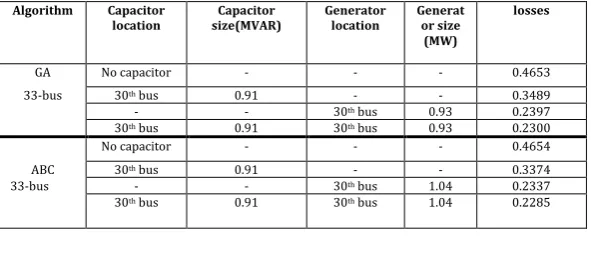
[image:4.595.151.447.314.448.2]exploration paper is acquired from load flow program on MATLAB programming are performed on a laptop with processor AMD-A4-3330MX APU with radeonTM HD design 2.20 GHz and RAM of 2.00 GB.By using genetic algorithm and Artificial bee colony algorithm, the optimal location andsize for capacitor and DG get obtained. We can easily compare the results of genetic algorithm with the results of ABC. Since ABC is a meta heuristic technique it gives more efficient results than genetic algorithm. Below are thetables showing the respective results of GA and ABC.
Table 1 shows the results of GA and ABC in 33 bus test system. The results clearly shows that ABC reduces more losses than GA also it is beneficial to use capacitor with DG to reduce the system losses more and more. In the table losses are calculated when no capacitor and DG is placed in the system, in this case loss is maximum, next losses are calculated after placing capacitor only. In this case losses get reduced. After this losses are calculated after placing both capacitor and DG, in this case losses are minimum.
Table 2 shows the results of GA and ABC in 69 bus test system. Here the size of DG get calculated first and then the reduction in losses is achieved by placing the generator optimally in the system.
TABLE 1
Shows the losses with location and size of generator and capacitor with GA and ABC for 33 bus test system
Algorithm Capacitor
location size(MVAR) Capacitor Generator location Generator size (MW)
losses
GA No capacitor - - - 0.4653
33-bus 30th bus 0.91 - - 0.3489
- - 30th bus 0.93 0.2397
30th bus 0.91 30th bus 0.93 0.2300
No capacitor - - - 0.4654
ABC 30th bus 0.91 - - 0.3374
33-bus - - 30th bus 1.04 0.2337
30th bus 0.91 30th bus 1.04 0.2285
TABLE 2
Shows losses with generator location and size using GA and ABC for 69 bus test system.
Algorithm Generator location Generator size(MW) Losses
GA-69 bus
2 variables Without generator - 0.5002
61st bus 1.769 0.1544
GA-69 bus Without generator - 0.5667
4 variables 61st bus 1.348 0.0745
25th bus 0.618
ABC-69 bus Without generator - 0.5002
2 variables 61st bus 1.297 0.1191
ABC-69 bus Without generator - 0.5375
4 variables 61st bus 1.263 0.0722
21ST BUS 0.606
[image:4.595.161.437.490.630.2]© 2016, IRJET | Impact Factor value: 4.45 | ISO 9001:2008 Certified Journal
| Page 2486
[image:5.595.159.414.265.391.2]Figure 1:Variation in voltage magnitude in 33 bus system by ABC
Figure 2: Variation in voltage magnitude in 33 bus system by GA
Figure 3: Variation in voltage magnitude in 69 bus system by GA
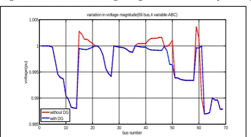
Figure 4:Variation in voltage magnitude in 69 bus system by ABC
0 10 20 30 40 50 60 70
0.985 0.99 0.995 1 1.005 bus number vo lt a g e (p u )
variation in voltage magnitude(69 bus,4 variable-GA)
without DG with DG
0 10 20 30 40 50 60 70
0.985 0.99 0.995 1 1.005 vo lt a g e (p u ) bus number
variation in voltage magnitude(69 bus,4 variable-ABC)
without DG with DG
0 5 10 15 20 25 30 35
0.93 0.94 0.95 0.96 0.97 0.98 0.99 1 bus number vo lt a g e (p u )
variations in voltage magnitude(by GA-33 bus)
without DG with DG
0 5 10 15 20 25 30 35
0.93 0.94 0.95 0.96 0.97 0.98 0.99 1 bus number vo lt a g e (p u )
variation in voltage magnitude(33 bus-ABC)
[image:5.595.159.413.431.565.2] [image:5.595.160.415.592.731.2]© 2016, IRJET | Impact Factor value: 4.45 | ISO 9001:2008 Certified Journal
| Page 2487
CONCLUSION
In this paper two optimization techniques are used to reduce the system losses effectively, these are Genetic Algorithm and Artificial Bee Colony algorithm. These two algorithms are used for both 33 bus test system and 69 bus test system to find out the optimal location and size of DG going to place in these systems for minimizing power losses and improving voltage profile. Here the results of both ABC and GA get compared and it is proved that ABC is more beneficial than GA, since ABC takes less time to operate and also gives more accurate results than GA. In 69 bus test system two generators are placed to minimize the system losses more. It is easy to compare that the losses with two DG placement is less than the losses with single DG placement. Hence it is beneficial to place more number of DGs in large bus systems to reduce the losses more.
ACKNOWLEDGEMENT
The paper presented over here is made possible through the support of my guide Mr Pushpendra singh, Assistant professor at GWEC Ajmer, he kindly read my research papers and guides me for the betterment of my research. I would like to thanks the faculties of EEE department for arranging some beneficial workshops.
Finally, I sincerely thank to my parents, family, and friends, who provide the advice and financial support. This paper would not be possible without all of them.
REFERENCES
[1] Ayse Aybike Sekar, Mehmet hakan Hacaoglu,”Artificial bee colony algorithm for optimal placement and sizing of distributed generation”, unpublished.
[2] Dharani hemant Kumar, P. Suresh Babu, M Padma Lalitha,”Reconfiguration
of distribution system network with distributed generation for loss reduction using artificial bee colony algorithm”,International jpournal of Recent Advances in Engineering and Technology,volume-1,issue-3,2013. [3] Mahdi Mozaffari Legha, Marjan Tavakoli, Farzaneh Ostovar, Milad Askari
Hashemabadi,”Capacitor placement in radial distribution system for improve network efficiency using artificial bee colony”,International Journal of Engineering Research and Applications, vol 3, Issue-6, Nov-Dec 2013.
[4] Mohd. Nabil Bin Muhtazaruddin, Nguyen Duc Turyen and Goro Fujita, Jasrul Jamani Bin Jamian, 2014 IEEE.
[5] Israfil Husain, Anjan Kumar Roy,”Optimal distributed generation allocation in distributed systems employing modified artificial bee colony algorithm to reduce losses and improve voltage profile”,IEEE-ICAESM-2012,march 30,31,2012.
[6] Seyed Abbas Tehar, Reza Bagherpour,”A new approach for optimal capacitor placement and sizing in unbalanced distorted distribution systems using hybrid honey bee colony
algorithm”,2013,Elsevier.
[7] Thomas Ackermann, Goran Andersson, Lennart soder,”Distributed
generation:a definition”,2001 Elsevier Science.
[8] W.S. Tan, M.Y. Hassan, M.S Majid,”Multi population genetic algorithm for allocation and sizing of distributed generation”,2012 IEEE, International Power Engineering and Optimization Conference, Melaka Malaysia:6-7 June 2012.
[9] Gopiya Naik S.,D.K. Khatod and M.P. Sharma,”Optimal allocation of distributed generation in distribution system for loss reduction”,2012 IACSIT Coimbatore Conferences, Vol 28. [10] M.Padma Lalitha, N.Sinarami Reddy, V.C. Veera Reddy,”Optimal DG
placement for maximum loss reduction in radial distribution system using ABC algorithm”,International Journal of Reviews in Computing, E-ISSN:2076-3336.
[11] Nur Fairuz Mohd Johan, Azral mukmin Azmi, Samila Mat Zali, Mohd Abdur
© 2016, IRJET | Impact Factor value: 4.45 | ISO 9001:2008 Certified Journal
| Page 2488
BIOGRAPHIES
Aakanksha Kumawat, has obtained 1st merit honours degree in Bachelor of Technology in Applied Electronics and Instrumentation from Compucom Institute of Technology and Management Jaipur (RTU) in 2013. She is pursuing her M.Tech in Power System from Govt. Women Engg. College, Ajmer. Her area of research is biomass, Distribution system and Power Loss Minimization.
Pushpendra Singh, has obtained degree in Bachelor of Engineering in Electrical from Rajasthan