© 2016, IRJET | Impact Factor value: 4.45 | ISO 9001:2008 Certified Journal | Page 1446
Optimization of Process Parameters of AISI D3 Steel with Abrasive
Assisted Drilling
Parminderjeet Singh
1, Kamaljeet Bhambri
21
Dept. of Mechanical Engineering, Shaheed Udham Singh College of Engineering and Technology Tangori,
Mohali,Punjab,India
2
Assistant Professor, Mechanical Engineering, Shaheed Udham Singh College of Engineering and Technology
Tangori, Mohali,Punjab,India
---***---Abstract –
This paper presents the optimization ofprocess parameters for the surface finish & material removal rate during the drilling of AISI D3 steel with HSS drill. This study includes drilling of AISI D3 steel with supply of silicon carbide abrasive having grain size 1200µm mesh size through abrasive slurry & with coolant also. The slurry concentration has been varied from 15-35% by weight. Abrasive slurry performs the function of coolant as well as increases the surface finish, MRR. Experiments were conducted on a CNC machine. Taguchi was applied for executing the planning of experiments. The drilling parameters including spindle speed (RPM), feed rate (mm/min), and slurry concentration are optimized using multiple performance characteristics for surface roughness and MRR. Although, feed rate and spindle speed, slurry concentration were the most significant factors which affect the surface roughness but an overall improvement of 26.51% in the surface roughness has been witnessed with the aid of abrasive slurry. The feed rate was the most significant factor for the material removal rate during the abrasive assisted drilling.
Key Words: Drilling, MRR, surface roughness, Taguchi method, Abrasive, Twist drill.
1. INTRODUCTION
Drilling is a process of producing round hole in solid material or enlarging existing hole with the use of multi-point cutting tools called drill or drill bits. Various cutting tools are available for drilling, but the most common is the twist drill. Drilling is one of the most fundamental machining processes. It is most frequently performed in material removal and it is used as a preliminary step for many operations such as reaming, tapping and boring. It is moving toward high speed applications for productivity enhancement. It has found that high production machining and drilling with high cutting velocity, feed and depth of cut is inherently associated with generation of large amount of heat and high cutting temperature which reduces surface
finish and tool life. Twist drills are the most common cutting tools used with drilling machines.
They are called twist drills mainly because of the helical flutes or grooves that wind around the body from the point to the neck of the drill and appear to be twisted. Twist drills are simply constructed but designed very tough to withstand the high torque of turning, the downward pressure on the drill, and the high heat generated by friction.
2 LITERATURE REVIEW
© 2016, IRJET | Impact Factor value: 4.45 | ISO 9001:2008 Certified Journal | Page 1447
process. Results indicate that the carbide tool is durable,showing minimal tool wear after drilling 11,000 holes, but observations also indicate the progressively severe abrasive grooving on the tool tip. C.C. Tsao [7] optimized the all machining operations; drilling using twist drill is the most frequently applied for secondary machining of composite materials owing to the need for structure joining. This study presents a comprehensive analysis of De-lamination caused by the drill wear for twist drill in drilling carbon fiber-reinforced composite materials. It results demonstrate that though the critical thrust force is higher with increasing wear ratio, the De-lamination becomes more liable to occur because the actual thrust force increases to larger extent. Quan Yanming [22] analyzed the tool wear in the cutting of SiC particle-reinforced aluminum matrix composites with special attention paid to the effects of material structures on the tool wear mechanism. The results of experiments show that the cutting of composites reinforced by coarse SiC particles requires tools which have high hardness: conventional tools are only adaptable to cut composites reinforced by fine SiC particles. J.Pradeep Kumar [16] utilized Taguchi method to investigate the effects of drilling parameters such as cutting speed , feed rate and drill tool diameter on surface roughness, tool wear by weight, material removal rate and hole diameter error in drilling of OHNS material using HSS spiral drill. Yogendra Tyagi [28] investigated the drilling of mild steel with the help of CNC drilling machine operation with the use high speed steel by applying Taguchi methodology. Different machining parameters i.e. spindle speed, depth of cut and feed rate were investigated in order to minimize the surface roughness and to maximize the material removal rate. B. Ramesh [4] analyzed a non laminated Glass Fiber Reinforced Plastic (GFRP) composite manufactured by pultrusion process. Drilling was done with a coated cemented carbide drill. Feed significantly influences both the thrust force and torque with 88.52% and 92.83% respectively whereas the influence of spindle speed on the above was relatively insignificant. Kapil Kumar [18] investigated the optimization of cutting parameters for improving surface finish of stainless steel SS304 in the abrasive assisted drilling. Feed rate and spindle speed are the most significant factors which affect the surface roughness but an overall improvement of approximately 11% in the surface roughness has been witnessed with the aid of abrasive slurry. Arshad Noor Siddiquee [3] focused on optimizing deep drilling parameters based on Taguchi method for minimizing surface roughness. All four cutting parameters significantly affected the surface roughness with maximum contribution from speed (27.02%), followed by cutting fluid (25.10%), feed (22.99%), and hole-depth (14.29%). B.V.Kavad [5] studied that both vibration assisted drilling and Ultrasonic assisted drilling are more appropriate for drilling of GFRP. Gaurav Chaudhary [11] studied that Metal matrix composites (MMCs) consisting of two or more physically/chemically distinct phases are potential material for aerospace, automobile, defense, sport and research industries.
Kamaldeep Singh [17] has done research work to find optimum process parameters for abrasive assisted surface grinding of AISI D3 tool steel. This study demonstrates that c-BN grinding wheel is preferred for higher MRR and Al2 O3 grinding wheel for better surface finish. Depth of cut is the most significant factor for both MRR and surface roughness.
3. EXPERIMENTATION
The HAAS TM1 Vertical Milling machine was used for experimentation. The twist drill bit was used in machining the work-piece. Preparing the slurry by taking concentration (gm/ml) of 15%, 25%, and 35%, with abrasive powder of Silicon carbide which has grit size 1200 µm. Stop-watch was used to determine material removal rate (MRR). For measuring surface roughness Mitutoyo (Surftest-4) was used. The corresponding MRR and surface finish was recorded for each experiment.
3.1 Machining Setup
The entire machining was carried out on 3-Axis HAAS TM1 Vertical Milling machine as shown in Figure 1. The HSS drill bit was used for drilling operation, diameter of 10 mm having two Flutes. Abrasive slurry of the silicon carbide (SiC) having grain size 1200 mesh was used as cutting fluid for present work. The slurry was used with varying concentration of 15%, 25%, and 35%. The work material used for the experimentation is AISI D3 steel. It is a high carbon high chromium tool steel. Material was cut into rectangular flats of 305*66*12 mm.
© 2016, IRJET | Impact Factor value: 4.45 | ISO 9001:2008 Certified Journal | Page 1448
3.2 Control factors and their limits
Table -1: Different control variables & their level
Factors Levels Level 1 Level 2 Level 3 Speed of
Spindle
(RPM) (A) 3 400 500 600
Feed Rate (mm/min)
(B) 3 30 50 80
Slurry concentration
(%) (C) 3 15% 25% 35%
3.3 L9 orthogonal array
[image:3.595.310.561.301.476.2]In the present investigation, three different process parameters have been selected such as feed rate, spindle speed (RPM), and slurry concentration have three levels each. As per the requirements of the study, L9 orthogonal array has come out as one of the possible solutions for designing the experiments.
Table -2 L9 orthogonal array
3.4 Experimental procedure
Firstly the material was cut into two equal parts of rectangular flats of size 305*66*12mm. After cutting, the AISI D3 steel material was holding on the vice fitted on CNC Machine. Then a program was made for each experiment as per the input parameters in orthogonal array. For each experiment, three holes were drilled into the AISI D3 steel plate to reduce error by taking the mean value. During the experiments, the abrasive slurry of Silicon carbide was used for first plate and coolant was used for second plate. Time
taken for drilling operation on work piece was recorded with the help of stop watch. Then surface roughness of work piece was measured with the help of Mtiutoyo Surftest-4 for all the machined samples.
4. RESULTS & DISCUSSIONS
After conducting the experiments with abrasive slurry, the values of output variables (MRR & surface roughness) were recorded & plotted as per Taguchi’s design & methodology. The analysis of the results obtained has been performed according to the standard procedure recommended by Taguchi. The detailed description of the analysis is given as under.
Table -3: Observation table
Exp.
No. MEAN MRR (mm³/sec) Ratio(dB) S/N Mean Ra S/N (d/B)
1 33.26 30.44 3.62 -11.17
2 48.75 33.76 4.17 -12.4
3 104.67 40.4 5.39 -14.64
4 37.72 31.53 4.41 -12.9
5 56.57 35.05 4.21 -12.48
6 91.35 39.21 4.97 -13.93
7 34.06 30.64 2.59 -8.27
8 60.18 35.59 4.95 -13.89
9 101.18 40.1 5.09 -14.14
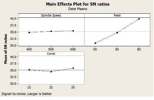
4.1 Effect on MRR
It is observed that the feed rate affects the Material Removal rate significantly. As the feed rate increases there is increase in material removal rate. With the lower of feed rate, material removal rate is also low. The maximum material rate value is observed at the feed rate of 80 mm/min.
Chart -1: Plot for S/N ratio (MRR) Sr.
No. Speed(RPM) Spindle (mm/min) Feed Slurry Const. (%)
1 400 30 15
2 400 50 25
3 400 80 35
4 500 30 35
5 500 50 15
6 500 80 25
7 600 30 25
8 600 50 35
[image:3.595.311.560.595.756.2]© 2016, IRJET | Impact Factor value: 4.45 | ISO 9001:2008 Certified Journal | Page 1449
Chart -2:Plots for Mean (MRR)
It is observed that material removal rate is maximum at feed rate 80 mm/min, spindle speed of 600 rpm, and slurry concentration of 35%.Also material removal is minimum at feed rate of 30 mm/min, spindle speed of 400 rpm and slurry concentration of 25%.
4.2 Effect on Surface Roughness
It is observed that the lower value of surface roughness is obtained with the abrasive assisted drilling as compared to the drilling with coolant. This can be explained on the basis of low removal rate during the silicon abrasive assisted drilling. As the removal rate is low, very less cavities found on the surface during drilling.
Chart -3: Plot for S/N ratio (Surface roughness)
Chart -4: Plot for Mean (Surface roughness)
Feed rate affects the surface roughness the most. It is observed that Surface finish is maximum at feed rate of 30 mm/min, spindle speed of 600 rpm, and slurry concentration of 25%. Also Surface finish is minimum at feed rate of 80 mm/min, spindle speed of 500 rpm, and slurry concentration of 35%.
4.3 Comparison-abrasive & coolant assisted drilling
For comparing abrasive assisted drilling with coolant assisted drilling, nine experiments were performed with SiC abrasive & SE-363 as coolant.
Table-4 Percentage comparison for MRR
Sr.
No. Abrasive Assisted Drilling
MRR (mm³/sec)
Drilling With Coolant
MRR (mm³/sec)
Improvement (%)
1 33.26 31.76 4.5
2 48.75 46.35 4.92
3 104.67 83.26 20.45
4 37.72 32.12 14.84
5 56.57 53.36 5.67
6 91.35 85.64 6.25
7 34.06 33.67 1.14
8 60.18 54.39 9.63
9 101.18 88.49 12.54
Average 8.88%
© 2016, IRJET | Impact Factor value: 4.45 | ISO 9001:2008 Certified Journal | Page 1450
Table-5 Percentage comparison for Surface RoughnessSr.
No. Abrasive Assisted Drilling RA
(µm)
Drilling With Coolant RA
(µm)
Improvement (%)
1 3.62 4.84 25.16
2 4.17 5.63 25.89
3 5.39 6.97 22.68
4 4.41 5.04 12.38
5 4.21 5.71 26.29
6 4.97 7.12 30.24
7 2.59 5.11 49.28
8 4.95 5.97 17.14
9 5.09 7.23 29.61
Average 26.51%
It observed that there is an average 26.51% increase in Surface Roughness when silicon carbide slurry is used instead of coolant.
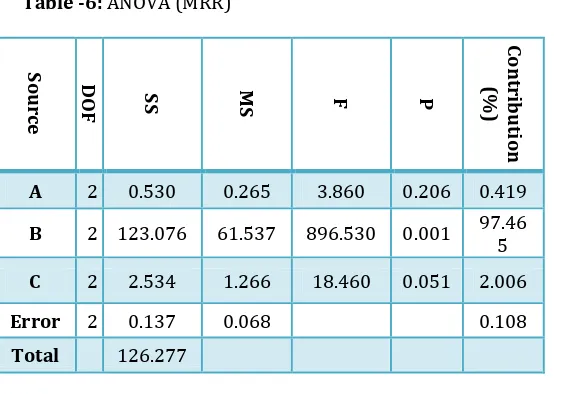
4.4 Analysis of Variance (ANOVA)
The percentage contribution of various process parameters on the selected performance characteristic can be estimated by performing analysis of variance test (ANOVA). Thus information about how significant the effect of each controlled parameter is on the quality characteristic of interest can be obtained. The total variation in the result is due to various controlled factors and their interactions and variation due to experimental error.
Table -6: ANOVA (MRR)
Source D
O
F SS MS F P
Con
tr
ibu
tion
(%)
A 2 0.530 0.265 3.860 0.206 0.419
B 2 123.076 61.537 896.530 0.001 97.465
C 2 2.534 1.266 18.460 0.051 2.006
Error 2 0.137 0.068 0.108
Total 126.277
After investigating the above data it is found that feed rate with percentage contribution of 97.47% & slurry concentration (2.01%) are the significant factor for material
removal rate. Spindle speed (0.42%) is non-significant parameters.
Table -7:
ANOVA (Surface Roughness)
Source D
O
F SS MS F P
Con
tr
ibu
tion
(%)
A 2 1.548 0.773 0.470 0.680 5.013 B 2 18.265 9.132 5.540 0.153 59.155
C 2 7.769 3.884 2.360 0.298 25.161 Error 2 3.295 1.647 10.671
Total 30.876
As per this experiment data for surface roughness, feed rate is the important factor to consider for surface finish during the abrasive assisted drilling of AISI D3 steel with a percentage of 59.16% and slurry concentration is also a important factor with contribution of 25.16%. Beside this, spindle speed has 5.01% contribution.
5. CONCLUSIONS
1. In case of surface finish, 25% slurry concentration and a feed rate of 30 mm/min with spindle speed of 600 rpm found to be optimized parameters for abrasive assisted drilling.
2. In case of Material Removal Rate, 35% slurry concentration and a feed rate of 80 mm/min with 600 rpm rotational speed found to be optimized parameters for abrasive assisted drilling.
3. When we compare the surface finish and MRR, the abrasive assisted drilling gives better result as compared to drilling with coolant.
4. In case of Abrasive assisted drilling (silicon slurry) versus drilling with coolant, the average improvement in surface roughness is 26.51%.
5. In case of Abrasive assisted drilling (silicon slurry) versus drilling with coolant, the average improvement in material removal rate is 8.88%.
6. All the selected parameters are affecting the results but feed rate has maximum effect on the surface finish in abrasive assisted drilling of AISI D3 steel.
7. Minimum value of Surface roughness is obtained at higher spindle speed (600 RPM) and lower feed rate (30 mm/min) at moderate slurry (25%) concentration. 8. The overall improvement in surface finish & MRR
© 2016, IRJET | Impact Factor value: 4.45 | ISO 9001:2008 Certified Journal | Page 1451
REFERENCES
[1] Adem Cicek & Turgay Kivak & Ilyas Uygur & Ergun Ekici & Yakup Turgut., “Performance of cryogenically treated
M35 HSS drills in drilling of austenitic stainless steels”,
International Journal Adv Manufacturing Technology, Volume 60, pp. 65–73, 2012.
[2] Anil Jindal., “Analysis of Tool Wear Rate in Drilling Operation using Scanning Electron Microscope (SEM)”, Journal of Minerals & Materials Characterization & Engineering, Vol. 11, No.1, pp.43-54, 2012.
[3] Arshad Noor Siddiquee, Zahid A. Khana, Pankul Goel, Mukesh Kumar, Gaurav Agarwal, Noor Zaman Khan., “ Optimization of Deep Drilling Process Parameters of AISI
321 Steel using Taguchi Method”, Procedia Materials
Science, Volume- 6, pp. 1217 – 1225, 2014.
[4] B. Ramesh, S. Joseph Cyril Sharan, R. Kavialagan.,
“Experimental investigation and optimization in drilling
GFRP polymeric composites using Taguchi and
ANOVA",International Journal of Mechanical and
Production Engineering, ISSN No. 2315-4489, Vol-2, Iss-1, 2013.
[5] B.V.Kavada, A.B.Pandey, M.V.Tadavi, H.C.Jakhari., “A Review Paper on Effects of Drilling on Glass Fiber
Reinforced Plastic”, Procedia Technology, Volume 14, pp.
457 – 464, 2014.
[6] C.C. Tsao, H. Hocheng., “Effect of tool wear on
delamination in drilling composite materials”,
International Journal of Mechanical Sciences, Volume 49, pp. 983–988, 2007.
[7] C.C. Tsao, H. Hocheng., “Evaluation of thrust force and surface roughness in drilling composite material using Taguchi analysis and neural network”, Journal of materials processing technology Volume 203, pp. 342– 348, 2008.
[8] C.C. Tsao, H. Hocheng., “Taguchi analysis of de-lamination associated with various drill bits in drilling of composite
material”, International Journal of Machine Tools &
Manufacture, Volume 44, pp. 1085–1090, 2004. [9] Deepak Pal, Ajay Bangar, Rajan Sharma, Ashish Yadav.,
“Optimization of Grinding Parameters for Minimum
Surface Roughness by Taguchi Parametric Optimization
Technique”, International Journal of Mechanical and
Industrial Engineering , ISSN No. 2231 –6477, Volume-1, Issue-3, 2012.
[10] Erkki Jantunen., “A summary of methods applied to tool
condition monitoring in Drilling”, International Journal of
Machine Tools & Manufacture, Volume 42, pp. 997– 1010, 2002.
[11] Gaurav Chaudhary Manoj Kumar, Santosh Verma, Anupam Srivastav., “Optimization of drilling parameters of hybrid metal matrix composites using response surface
methodology”, Procedia Materials Science, Volume 6, pp.
229 – 237, 2014.
[12] Gul Tosun, Mehtap Muratoglu., “The drilling of Al/SiCp metal–matrix composites. Part II: work piece surface
integrity”, Composites Science and Technology, Volume
64, pp. 1413–1418, 2004.
[13] H. Liu a, J. Wanga, N. Kelson, R.J. Brown., “A study of
abrasive waterjet characteristics by CFD simulation”,
Journal of Materials Processing Technology, number 153–154, pp. 488–493, 2004.
[14] H.S. Liu, B.Y. Lee, Y.S. Tarng., “In-process prediction of
corner wear in drilling operations”, Journal of Materials
Processing Technology, Volume 101, pp. 152-158, 1998. [15] Hans B. Kief, Helmut A. Roschiwal., “CNC Handbook”
McGraw-Hill Education, New York, pp. 30-31, 2012. [16] J.Pradeep Kumar, P.Packiaraj., “Effect of drilling
parameters on surface roughness, tool wear, material removal rate and hole diameter error in drilling of ONHS”, International Journal of Advanced Engineering Research and Studies E-ISSN2249–8974, Vol. I, Issue III, pp. 150-154, 2012.
[17] Kamaldeep Singh, Dr. Beant Singh, Mandeep Kumar., “Experimental Investigation of Machining Characteristics of AISI D3 Steel with Abrasive Assisted Surface Grinding”, International Research Journal of Engineering and Technology, E-ISSN: 2395-0056, P-ISSN: 2395-0072, Volume. 02, Issue: 04, 2015.
[18] Kapil Kumar Goyal, Vivek Jain, Sudha Kumari., “Prediction of Optimal Process Parameters for Abrasive
Assisted Drilling of SS304”, Procedia Materials Science,
Volume 6, pp. 1572 – 1579, 2014.
[19] Kyung-Hee Park, Aaron Beal, Dave Kim, Patrick Kwon, Jeff Lantrip., “Tool wear in drilling of composite/titanium
stacks using carbide and polycrystalline diamond tools”,
Wear, Volume 271, pp. 2826– 2835, 2011.
[20] M. Ramulu, P.N. Rao, H. Kao., “Drilling of (Al2O3)p/6061
metal matrix composites”, Journal of Materials
Processing Technology, Volume 124, pp. 244–254, 2002. [21] Murthy B.R.N, Lewlyn L.R. Rodrigues and Anjaiah
Devineni., “Process Parameters Optimization in GFRP Drilling through Integration of Taguchi and Response
Surface Methodology”, Research Journal of Recent
Sciences ISSN 2277-2502, Vol. 1(6), pp. 7-15, 2012. [22] Quan Yanming, Zhou Zehua., “Tool wear and its
mechanism for cutting SiC particle-reinforced aluminum
matrix composites”, Journal of Materials Processing
Technology, Volume 100, pp. 194-199, 1998.
[23] Rajender Singh, “Introduction to basic manufacturing
processes and workshop technology”, New Age
International (P) Ltd., New Delhi, pp.-430, 2006. [24] Resit Unal, Edwin B. Dean., “Taguchi Approach to Design
Optimization for Quality and Cost”, Annual Conference of
© 2016, IRJET | Impact Factor value: 4.45 | ISO 9001:2008 Certified Journal | Page 1452
[25] Scott F. Miller, Peter J. Blau, Albert J. Shih., “Tool wear in
friction drilling”, International Journal of Machine Tools
& Manufacture, Volume 47, pp. 1636–1645, 2007. [26] T. Rajmohan, K. Palanikumar, M. Kathirvel.,
“Optimization of machining parameters in drilling hybrid
aluminum metal matrix composites”, Trans. Nonferrous
Met. Soc. China, Volume 22, pp. 1286−1297, 2012. [27] Yanming QUAN, Wenwang ZHONG., “Investigation on
drilling-grinding of CFRP”, Front. Mech. Eng. China,
Volume 4(1), pp. 60–63, 2009.
[28] Yogendra Tyagi, Vedansh Chaturvedi, Jyoti Vimal.,
“Parametric Optimization of Drilling Machining Process
using Taguchi Design and ANOVA Approach”,