© 2016, IRJET | Impact Factor value: 4.45 | ISO 9001:2008 Certified Journal | Page 2209
Optimization of balance weight of unbalanced turning operation with
optimized cutting parameter
Prof. Hemant K. Shete
DACOE Karad, Maharashtra, India
DACOE Karad, Maharashtra, India
Prof. Vishal N. Gandhe
---***---Abstract – In unbalanced turning operation on lathe machine counter weight position and its weights is most desiring parameter. The aim of the present work is to optimize counter weight and its position with optimized cutting parameter for machining of the bearing cap from engine of tractor .Computer Aided Mass Balancing (CAMB) methodology is used for determining the counter weight for rotary turning fixture. The performance characteristics in terms of surface roughness are studied by using the orthogonal array S/N ratio, And the ANOVA from Taguchi method for interrupted cuts of boring operation and effect of Cutting force for balanced and unbalanced rotary fixture.
Key Words:
CAMB, Rotary fixture, Bearing cap,
Surface roughness etc…
1. INTRODUCTION
In the manufacturing process, material removal process comes after primary manufacturing process. In metal machining process turning operation of cylindrical parts are machined on lathe machine. It is very common machine to machine cylindrical components. Present work includes the machining of half round component with interrupted cuts. Experimental work is done on bearing cap from tractor engine. And it is form famous tractor company. The material of bearing cap is cast iron. Rotary fixture is designed for machining on lathe machine. Boring, internal grooving and both side facing are the operations to be performed on work piece. As there is mounting of another cap inside the bearing cap surface required should free from chatter marks. But for machining of bearing cap we can mount only 1 component on fixture and as cutting tool is only partially in contact in a revolution. It generates interrupted cut while machining internal surface which shows chatter mark on internal surface.
To avoid unbalancing of fixture, fixture must be balanced by adding the counterweight on rotary fixture to minimize effect of cutting forces acting on the tool. The fixture can
be balanced by dynamic balancing machine. In present work rotary fixture is balanced by Computer Aided Mass Balancing (CAMB) methodology. The methodology for balancing rotary fixture is used to calculate counterweight to be added on rotary fixture along with its position. This method of balancing the rotary fixture is commonly used in the industry.
2 Computers Aided Mass Balancing (CAMB) for
Rotary Fixture
The balancing in present work is required in rotational motions. The balancing is achieved by adding the counter weight or by unbalanced mass removal. These methods performed on balancing machine. The Computer Aided Mass Balancing (CAMB) methodology saves time and money consuming in regular practice by manual method. In this paper 3D high end modeling software “Creo 2.0 “is used to predict / calculate the counterweight to be added on rotary fixture well before manufactured. Hence there is no need to be balance the rotary fixture after manufacturing, as it gives the value of counterweight to be added.
C. G. and weight of fixture are determined in “Creo 2.0 “. Center of gravity is offset from axis of rotation of rotary fixture in x axis by -204.90mm and in y axis by 218.23 mm Ad in z axis by 73.58mm According to principles of mechanics, F = 0 and M=0
Figure: 1.10
© 2016, IRJET | Impact Factor value: 4.45 | ISO 9001:2008 Certified Journal | Page 2210 For the experimentation following parameters are
selected by considering the work piece material, lathe machine specifications. L9 orthogonal array is selected for experimentation from MINITAB to perform different combinations
.
3.1 Selection of the levels for the factors
In the present experimental study, cutting speed, feed rate, depth of cut and balanced and unbalanced rotary fixture have been considered as process variables [11].
1. Cutting Speed
Cutting speed is defined as linear speed at the tool/work piece contact area. This speed is measured in revolution per minute (rpm). Three levels of cutting speed were selected.
The upper and lower levels are selected by considering the machine speed. The three levels of cutting speed are 200rpm, 275rpm and 400rpm.
2. Feed
The tool feed is the relative motion of the cutting tool with respect to the work-piece. It is measured in millimeters per revolution (mm/rev.) Cracks, pits and chatter marks on the machined surfaces are increases with increase in feed rate, due to reinforcement pull-out and fracture. It deteriorates the surface quality and produces higher thermal stresses on the machined surfaces. The feed value increases then the surface finish of the work-piece reduces. Three levels of feed rate are 0.1 mm/rev, 0.15 mm/rev, and 0.5mm/rev.
3. Depth of cut
The depth of the tool along the radius of the work-piece as it makes a cut, as in a boring and facing operation. A large depth of cut will require a low feed rate, or else it will result in a high load on the tool and reduce the tool life.
4. Cutting conditions
[image:2.595.114.477.576.742.2]One of the objectives of this research is to study the effect of unbalanced and balanced conditions of the rotary fixture on surface roughness, MRR and forces acting on tool. The levels of input parameters are shown in Table 3.1
Table 3.1: The levels of input parameters Parameters Level 1 Level 2 Level 3
Speed (rpm) 200 275 400
Feed (mm/rev) 0.1 0.15 0.2
Depth of cut
(mm) 0.25 0.50 0.75
3.2 Selection of the appropriate experimental design and assignment of factors to experimental design. The working ranges of the parameters for subsequent design of experiment, based on Taguchi’s L9 Orthogonal array (OA) design have been selected. In this experiment, there are three parameters at three levels each. Experiments are carried out by using L9 orthogonal array. That orthogonal array is chosen because of expected accuracy in the experimental results. Table 3.2 shows the L9 array.
Table 3.2: L9 Orthogonal Array Trial
No. Speed (rpm) (mm/rev) Feed
Depth of cut (mm)
1 200 0.10 0.25
2 200 0.15 0.50
3 200 0.20 0.75
4 275 0.10 0.50
5 275 0.15 0.75
6 275 0.20 0.25
7 400 0.10 0.75
8 400 0.15 0.25
9 400 0.20 0.50
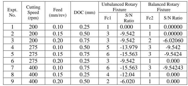
Table 3.3: Experimental Results and Analysis using S/N ratio:
Expt. No.
Cutting Speed (rpm)
Feed
(mm/rev) DOC (mm)
Unbalanced Rotary Fixture
Balanced Rotary Fixture
Fc1 S/N
Ratio Fc2 S/N Ratio
© 2016, IRJET | Impact Factor value: 4.45 | ISO 9001:2008 Certified Journal | Page 2211
4 FIXTURE BALANCING ANALYSIS
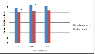
4. 1 Effect of Balancing On Surface Roughness
(RA)
At the cutting speed 200 rpm, the surface roughness (Ra) is more for unbalanced rotary fixture, by balancing the rotary fixture the surface roughness is minimizes. The effect of balancing the rotary fixture can be seen in following graphs. At the cutting speed 275 rpm and 400 rpm, the surface roughness is minimizes by balancing the rotary fixture.
Figure 4.10: Feed rate Vs. Surface Roughness at Cutting speed: 200 rpm; Depth of cut: 0.25, 0.50, 0.75 mm at the three regions a, b and c respectively
Figure 4.11: Feed rate Vs. Surface Roughness, Cutting speed: 275 rpm; Depth of cut: 0.50, 0.75, 0.25 mm at the three regions a, b and c, respectively
Figure 4.12: Feed rate Vs. Surface Roughness, Cutting speed: 400 rpm; Depth of cut: 0.75, 0.25, 0.50 mm at the three regions a, b and c, respectively
4.2 Surface Roughness Analysis
[image:3.595.326.546.100.238.2]4
.2.1 Boring operation for balanced rotary fixture 4 Figure.13 presents main effect plot of the S/N ratio for three control parameters cutting speed, feed and depth of cut for boring operation (balanced rotary fixture).Figure 4.13: Effect of cutting Speed, feed and Depth of cut on Surface Roughness (BB)
Effect of cutting Speed:
The effect of parameter cutting speed on the surface roughness values is shown above for S/N ratio. The surface roughness is increases with increase in cutting speed from 200 rpm to 275 rpm and further decreases. So, the optimum cutting speed level is 200 rpm.
Effect of feed:
The effect of parameter feed rate on the surface roughness values are shown above for S/N ratio. The surface roughness decreases as feed increases. So, the optimum feed rate level is 0.15 mm/rev.
Effect of Depth of cut:
[image:3.595.80.243.231.324.2]The effect of parameter depth of cut on the surface roughness values is shown above for S/N ratio. The surface roughness increases with increase in depth of cut. So, optimum depth of cut is 0.5 mm .
Figure 4.14: Main effect plot for surface roughness (BB)
The Figure 4.14 shows the main effect plot for surface roughness. The cutting speed has linear relationship with the surface roughness; it decreases up to 275 rpm and further increases up to 400 rpm. In case of feed it increases with increase in feed rate. In case of depth of cut it decreases with increase in depth of cut.
[image:3.595.328.540.461.596.2]© 2016, IRJET | Impact Factor value: 4.45 | ISO 9001:2008 Certified Journal | Page 2212
Level
Cutting Speed (rpm)
Feed (mm/rev)
DOC (mm)
Mean S/N Ratio
1 -15.98 -13.59* -15.80 2 -14.34* -15.35 -15.06 3 -15.14 -16.52 -14.60* Delta 1.64 2.93 1.21
Rank 2 1 3
As experiments are performed for cutting speed in the range of 200 to 400 rpm, feed in the range 0.1 to 0.2 mm/rev and depth of cut in the range of 0.25 to 0.75 mm, significance of surface roughness was determined by signal to noise ratio analysis as shown in Table 4.14. In this table starred values shows corresponding highest S/N ratio values showing best levels for each process parameter. Significance of machining parameters (Difference between max. and min. values) indicates that depth of cut is significantly contributing towards machining performance as difference gives higher values. Therefore, most influencing parameter is depth of cut. The S/N ratio analysis shows that optimized process parameters corresponding to surface roughness are Vc=275 rpm, f=0.1 mm/rev and DOC=0.75 mm which will yield the minimum surface roughness.
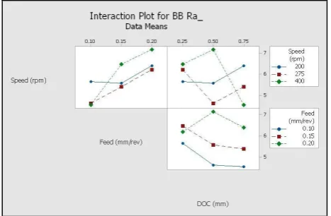
Figure 4.14: Surface roughness Interaction plot (BB) The interaction plot indicates that at higher speed the surface roughness increases and as speed decreases the surface roughness also decreases. It is seen that from interaction plot the cutting speed and feed, cutting speed and depth of cut affects more on surface roughness.
5 RESULTS
5.1. Boring for unbalanced rotary fixture
The Results of ANOVA for the surface roughness of unbalanced rotary fixture boring operation are shown in
Table 5.20. For unbalanced rotary fixture, ANOVA of the boring operation is as follows. The main effect of feed (the most significant parameter), Cutting speed (significance bellow the feed rate) are significant. It is evident that 76.228% feed is contributing on surface roughness than other cutting parameters. The cutting speed is next contributing factor whose contribution is 12.175% and lowest contribution from depth of cut which is 5.941%. Table 5.10: ANOVA (Surface Roughness) of boring operation for unbalanced rotary fixture
5.2. Boring for balanced rotary fixture
The Results of ANOVA for the surface roughness of balanced rotary fixture boring operation are shown in Table 5.21. For unbalanced rotary fixture, ANOVA of the boring operation is as follows. The main effect of feed (the most significant parameter), Cutting speed (significance bellow the feed rate) are significant. It is evident that 64.691% feed is contributing on surface roughness than other cutting parameters. The cutting speed is next contributing factor whose contribution is 20.107% and lowest contribution from depth of cut which is 8.897%.
Table 5.11: ANOVA (Surface Roughness) of boring operation For balanced rotary fixture
Sr. No.
Factor D O F
Sum of Squares
Mean Squares
F P %
Cont ribu tion 1 Speed 2 1.625 0.812 3.1 0.2 20.1 2 Feed 2 5.228 2.614 10.2 0.08 64.6
9 3 DOC 2 0.719 0.359 1.4 0.4 8.89 4 Error 2 0.509 0.254
5 Total 8 8.082
S=0.504771 R-sq=93.70% R-sq(adj)= 74.78%
6 CONCLUSIONS
An integrated approach is used for performing this study. Actually VMC is the best solution for performing these types of jobs. But by using lathe machine or CNC machine we simply perform these types of operations. The balancing of rotary fixture is done by analytical method using ‘Creo 2.0’. VMC costs very high, but by using lathe or CNC cost can reduce and CAMB is methodology can give us counterweight for balancing of rotary fixture.
Sr.
No. Factor D O F
Sum of Squares
Mean
Squares F P % Cont ribut ion 1 Speed 2 0.532 0.266 2.1 0.3 12.1 2 Feed 2 3.338 1.669 13.6 0.06 76.2 3 DOC 2 0.260 0.130 1.06 0.48 5.9 4 Error 2 0.244 0.122
5 Total 8 4.376
[image:4.595.54.271.97.241.2] [image:4.595.44.278.450.603.2] [image:4.595.298.571.553.657.2]© 2016, IRJET | Impact Factor value: 4.45 | ISO 9001:2008 Certified Journal | Page 2213 Interrupted cuts like facing, turning, boring (internal
turning) can harm the tool. These forces are optimized by Taguchi method. It is recommended that the frequently rotary fixture balancing need not be done, simply CAMB analytical method can give counterweight. This method can be used for regular routine balancing of the rotary fixture, hence it saves time and cost.
REFERENCES
[1] N. P. Maniar1, D. P. Vakharia2, Design, Modelling & Analytical Analysis of Rotary Fixture for CNC with an Approach of Computer Aided Mass Balancing Method, International Journal of Engineering Inventions e-ISSN:2278-7461, p-ISBN: 2319-6491 Volume 2, Issue 3 (February 2013)PP: 10-21.
[2] Hunter, R.; Rios, J.; Perez J. M.; Vizan, A. A functional approach for the formalization of the fixture design process.
International Journal of machine tools and manufacture, 2006,46, pp. 683–697.
[3] Bo Li; Shreyes N. Melkote. Improved work piece location accuracy through fixture layout optimization.
International Journal of machine tools and manufacture, 1999, 39, pp. 871–883.
[4] Nirav P. Maniar1*, D. P.Vakharia2, Comparative Study of Rotary Fixture Design – A Review, Int. J. on Recent Trends in Engineering & Technology, Vol. 05, No. 04, Mar 2011.
[5] Chigbogu C. Ozoegwu1,*, Christian. C. Nwangwu2,Chigozie F. Uzoh3, Arinze V. Ogunoh4, zPure AnalyticalApproach to Rotational Balancing, Journal of SafetyEngineering 2012, 1(4): 50-56 DOI: 10.5923/j.safety.20120104.01.
[6] Rodrigues L.L.R. 1, Kantharaj A.N. 1, Kantharaj B. 2,Freitas W. R. C. 2 and Murthy B.R.N. 1, Effect of CuttingParameters on Surface Roughness and Cutting Force in Turning Mild Steel, Research Journal of Recent Sciences ISSN 2277-2502 Vol. 1(10), 19-26, October (2012).
[7] D.V.V. Krishan Prasad, Influence of Cutting Parameters on Turning Process Using Anova Analysis, Research Journal of Engineering Sciences ISSN 2278 – 9472 Vol. 2(9), 1-6,September (2013).
[8]Shunmugesh K. 1, Panneerselvam K. 1 and Pramod M. 2 and Amal George 2, Optimization of CNC Turning Parameters with Carbide Tool for Surface Roughness Analysis Using Taguchi Analysis, Research Journal of Engineering Sciences ISSN 2278 – 9472 Vol. 3(6), 1-7, June (2014).
BIOGRAPHIES
Prof. Shete H. K. Asst. Prof.
Dr. Daulatrao Aher College of Engineering, Karad.
Prof. Gandhe V. N Asst. Prof.