Finite Element Analysis of the Bending Behaviour for
Triangular Web Profile with Opening Steel Section
De’nan F.*, Osman. M.H.**, Saad S.**, Hashim N.S.* and Sharizal N.*
*School of Civil Engineering, Engineering Campus, Universiti Sains Malaysia, 14300 Nibong Tebal, Pulau Pinang, Malaysia **Faculty of Civil Engineering, Universiti Teknologi Malaysia, 81310 Skudai, Johor, Malaysia
Abstract- The new steel section known as triangular web profile (TriWP) was studied by previous researcher to replaced flat web (FW) steel section for better resistance on bending behaviour. In order to reduce the weight of TriWP steel section for economic purposes opening on the web steel section is introduced. This paper described the study on the bending behaviour in major axis and mainly focus on the effect of opening on the TriWP, effect of the web thickness on triangular web profile with opening (TriWP with opening) steel section and effect of different type of opening shape on TriWP with opening. The TriWP with opening steel section with 200×100×6×3 mm size was analyze using finite element analysis. From finite element analysis it can be observed that the deflection on TriWP steel section is less compared to that TriWP with opening steel section. The different of deflection between TriWP with opening steel section and TriWP steel section is less than 1 mm. The deflection of the section based on manual calculation is 1.292 mm which is less than 8.33 mm, deflection limit of the section. Therefore TriWP with opening can resist and carry the same load as TriWP steel section can carry.
Index Terms- Bending behaviour, web thickness, finite element analysis, triangular web profile with web opening, weight.
I. INTRODUCTION
Two parameters which are fundamentally important to the design of beams are shear force and bending moment. These quantities are the result of internal forces acting on the material of a beam in response to an externally applied load system [1]. A beam is a horizontal structural element that is capable of withstanding load primarily by resisting bending. The bending force induced into the material of the beam as a result of the external loads, span, own weight, and external to these loads is called a bending moment. Beam theory shows that I-shaped section is a very efficient form for carrying both bending and shears loads into the plane of the web [2].
In many instances, it is necessary to support heavy vertical loads over long spans resulting large bending moments and shear forces. The I-section beams or H-piles are commonly used in structural steel works. Ordinary shapes of these beams are constructed from two parallel flanges and a web where about 30–40% of the entire weight of a medium flange width or narrow flange type of beam is contributed by the web part. The vertical-corrugated web beam (VCRx) could carry between 13.3 and 32.8% higher moment compared to the plane and horizontal-corrugated web beams, for the range of corrugation radius taken. In addition, larger corrugation radius could sustain higher bending load up to the yielding
stage [3]. In construction application, the flanges support the major external loads while the web usually bears most of the compressive stress and transmits shear in the beam. Materials saving could be achieved by using greater part of the material for the flanges and thinner web without weakening the load-carrying capability of the beam. The use of corrugated webs to increase the out-of-plane stiffness and buckling strength without the use of vertical stiffeners has been considered for some time, first in aircraft design, and later for civil engineering applications in buildings and bridges [4].
Welding of intermediate stiffeners could add to the fabrication cost and result in increase of the self weight of the girder. Use of stiffeners could, however, be eliminated if corrugated webs are used instead of plain web plates. The corrugated profile in the web provides a kind of uniformly distributed stiffening in the transverse direction of a girder, increases the out-of-plane stiffness and buckling strength. Compared to plate girders with stiffened flat webs, a girder with a trapezoidal corrugated web enables the use of thinner webs, thus for less cost a higher load-carrying capacity is achieved [5]. The usage of larger thickness and stiffeners that contributed to the reduction in beam weight and cost could be eliminated. Elgaaly et. al has been carried out an earlier study and has been further develop to the practical stages [6]. In aircraft design, the use of corrugated webs to increase the out-of-plane stiffness and buckling strength without the use of vertical stiffeners has been considered for some time and later for civil engineering applications in buildings and bridges [7].
In addition stiffeners properties are adequate to avoid excessive deflection or local buckling of the cross section in order to ensure that beams have sufficient strength capacities to resist these effects. The behavior of steel circular tubes under pure bending is complex and highly nonlinear. Most of the solutions are complicated and difficult to use in routine design practice even though has a number of solution to predict the response of steel circular tubes under pure bending. The feasibility of using artificial neural networks (ANNs) for developing more accurate and simple-to-use models is investigated for predicting the ultimate pure bending of steel circular tubes [8].
times. The ultimate bending strength was 25% larger than the steel box girder model and the ductility was about 6.5 times larger was shown in the tests with the half concrete filled steel box girder model. The half concrete filled steel box girder model without vertical stiffeners had the same ultimate bending strength of that of the girder with vertical stiffeners but the ductility was about half. By using fiber models the simple calculation method was developed [10]. Previous research has shown that a corrugated web I-girder under in-plane moment and shear will deflect in-in-plane and twist out-of-plane simultaneously. The out-of-out-of-plane twisting behavior can be analyzed as a flange transverse bending problem, solutions for web profiles with piecewise linear folds using the so-called fictitious load method and closed form solutions [11]. The efficiency of pre stress improves by utilizing the corrugated steel web introduced into the top and bottom flanges due to the accordion effect which also provides better deflection control and greater resistance against out-of-plane and local buckling. Additionally, the slanting plate of the corrugated web induces bearing stress that can improve composite action between the steel beam and the surrounding concrete when the corrugated steel web becomes composite with the concrete [12].
Ordinarily, the economic design of steel web I-beam requires thin web. Intermediate stiffener has to be used to avoid shear buckling or alternatively the web can be made corrugated in trapezoidal profile. When beams with corrugated webs are compared with those with stiffened flat webs, it can be found that trapezoidal corrugation in the web enables the use of thinner webs and trapezoidal web beams eliminate costly web stiffeners [13].
The presence of web openings of different proportions and the effects on the behaviour and ultimate strength of the girders are also investigated. The results show that all the steel beams with various shapes and sizes have similar deformed shapes and yield patterns under a wide range of applied moments and shear forces [14]. Optimum designs of steel structures with web openings have been carried out. 5% reduction of the weight achieved with shell element discretization compared to the beam element. This reduction is due to the attributed to the different constraint checks imposed by the design codes for each type of discretization. There are stress-based constraints for shell elements and stress-resultant constraints for the beam are used. When web openings are considered in the beams of the structure, around 20% improvement achieved with shell discretization is found [15].
In structural and fabrication technology, new techniques of optimized steel structures design have been developed. One of the developments in steel structure design is the introduction of trapezoidal web beam and triangular web profile. Beams in bending develop tension and compression in their flange. The bending capacity is limited by how much force can it take and resists the load apply to it. Beams generally carry vertical gravitational forces but can also be used to carry horizontal loads (i.e., loads due to an earthquake or wind). The loads carried by a beam are transferred to columns, wall or girders, which then transfer the force to adjacent structural compression member.
In this paper, results from preliminary investigation, the introduction of opening on triangular web profile steel section
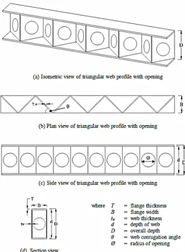
[image:2.595.310.573.134.492.2](TriWP with opening) is to reduce the weight of the section and compare the strength to that of triangular web profile steel section without opening (TriWP). In addition, different type/shape of opening and various web thicknesses are presented to determine the effects on triangular web profile steel section with opening (TriWP with opening).
Figure 1: Shape and dimensions of a typical TriWP with
opening (all units are in mm)
A. Theoretical calculation using EC3
Bending behavior of triangular web profile with opening (TriWP with opening) steels section is the first priority study for this paper. This paper focused on theoretical part and finite element analysis of TriWP with opening steel section towards bending behaviour.
Clause 6.2.8(2) states that provided the applied shear force is less than half the plastic shear resistance of the cross section its effect on the moment resistance of the cross section may be neglected. For cases where the applied shear force is greater than half the plastic shear resistance of the cross section, the moment resistance should be calculated using reduced design strength for the shear area, given by equation (1):
Fyr = (1 – ρ)fy (1)
Where ρ is defined by equation (2),
Vpl,Rd may be obtained from clause 6.2.6, and when
torsion is present Vpl,Rd should be replaced by Vpl,T,,Rd ,
obtained from clause 6.2.7. An alternative to the reduced design strength for the shear area, defined by equation (1), which involves somewhat tedious calculations, is equation (3). Equation (3) may be applied to the common situation of an I section (with equal flange) subjected to bending about the major axis.
In this case the reduced design plastic resistance moment allowing for shear given by
My,V,Rd = [(Wpl,y – ρAw2/4tw)fy] / γM0
but My,V,Rd≤ My,C,Rd (3)
Where ρ is defined by equation (2), My,C,Rd may be obtained
from clause 6.2.5 and Aw = hwtw. The triangular web profile
(TriWP) with an opening steel section specimen was modeled in LUSAS to conduct FEM analysis.
II. METHODOLOGY
Two method of approach are used to obtain the results and to achieve the objective of this study. The methods used are manual calculation by using Euro code standard and finite element analysis (modelling). Euro code is well known now in structural industry. Manual calculation is carried out to determine the characteristic of bending of triangular web profile (TriWP) with opening steel section by using Euro code 3 (EC3). On the other hand, finite element analysis is done by using LUSAS software where to performed computer based analysis of the various variable of the component. There are various variable that are carried out on the steel section such as the value of the load applied to it, the thickness of the web, the depth of the section and the size or shape of the opening on the web profile.
III. TEST PROCEDURES
A. Manual Calculation using Euro code 3
Safety factors used for checking ultimate limit state and serviceability limit state for steel building is 1.0 (γm).
Assumptions used in design are all beams considered as simply supported, all connection is designed to resist only resultant reactions at the appropriate eccentricity, columns are subjected to vertical loads applied at the appropriate eccentricity and resistance of sway forces such as those resulting from wind loads is provided by bracing shear wall. Design values of material coefficient to be used are modulus of elasticity, E = 210 000 N/mm2, poisson’s ratio, v = 0.3, coefficient of thermal expansion, α = 12 x 10-6 / oC (for temperature below 100 oC) and ε = √ 235/ fy.
B. Finite Element Analysis
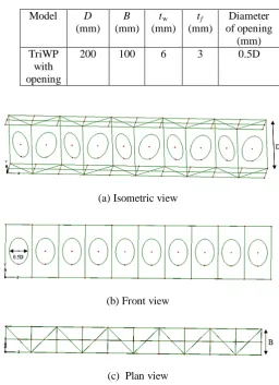
For this study, the properties of the model are 200×100×6×3 mm which 200 mm is the depth of the web (D), 100 mm is the flange width (B), 6 mm is the thickness of the flange (tf) and 3mm is the web thickness (tw). There are several steps to conduct finite element analysis using Lusas software. First, need to create a new model by define origin of
the model and insert the coordinate of the model based on the properties of the model respectively. After that, create surface on the model start from the flange and the web of the model. Then, create circle on the web and set up meshing, geometry, material, support included the loading and drag all of them to the section before run the program.
Table 1: The dimensional properties of models for the analysis
(a) Isometric view
(b) Front view
(c) Plan view
Figure 2: View of a TriWP with opening steel section model
IV. RESULTS AND DISCUSSION
There are many factors that may influence the bending behaviour of the triangular web profile with opening (TriWP with opening) steel section such as effect of web thickness (tw), depth of web (D) and corrugation angle (θ). This study is to investigate the influences factor of bending behaviour on TriWP with opening steel section. It is mainly focuses on the shape of opening with constant value of diameter, 0.5D and the effect of web thickness on the TriWP with opening steel section.
A. Effect of the Opening
Two models of triangular web profile (TriWP) steel section is analyze using finite element analysis which is with opening and without opening. Each model is test under load condition of 10kN point load on top and centre of the steel section. The section was 200×100×6×3 mm with various length of span for both models. The result of analysis is
Model D
(mm)
B
(mm)
tw
(mm)
tf (mm)
Diameter of opening
(mm) TriWP
with opening
[image:3.595.307.564.157.511.2]shown in Table 2 and load versus deflection for each length of span of both models is shown in Figure 3.
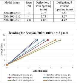
Table 2: Deflection results of the bending due to the effect of opening [Section (200×100×6×3) mm]
Model (mm) Span
(m)
Deflection, δ with opening
(mm)
Deflection, δ without opening (mm)
200×100×6×3 3 2.78 2.61
200×100×6×3 4 3.73 3.37
[image:4.595.303.566.50.660.2]200×100×6×3 4.8 4.85 4.42
Figure 3: Plots of load versus deflection on a TriWP with opening and TriWP steel section
It can be observed that the triangular web profile steel section (TriWP with opening) with opening has a bigger value of deflection compared to that of triangular web profile (TriWP) steel section. The different of deflection between TriWP with opening steel section and TriWP steel section is less than 1 mm, which means the deflection of the section based on manual calculation is 1.292 mm which is less than 8.33 mm, deflection limit of the section. Therefore TriWP with opening can resist the same load as TriWP steel section.
B. Effect of the Web Thickness, tw
The influence of web thickness on bending resistance is investigated in this study. There are seven models of different type of opening shape on triangular web profile with opening (TriWP with opening) steel section. The web thicknessesthat are considered in this study are 1 mm, 2 mm, 3 mm, 4 mm and 5 mm. Other geometric parameters such as B = 100 mm,
D = 200 mm and tf = 6 mm are keep constant.The results of analysis are shown in Table 3 and load versus deflection for each type of web thickness on various type of opening shape is presented on Figure 4 to Figure 10 respectively.
Table 3: Deflection results of the bending due to the effect of web thickness
Type of opening shape
Web thickness (mm)
Deflection, δ (mm)
Circle
1 2 3 4 5
5.47 3.84 3.29 3.02 2.85
Octagon
1 2 3 4 5
4.51 3.36 2.97 2.78 2.66
Diamond
1 2 3 4 5
3.93 3.07 2.78 2.63 2.54
Square
1 2 3 4 5
6.09 4.15 3.50 3.17 2.98
Triangular
1 2 3 4 5
4.27 3.24 2.89 2.72 2.61
Trapezoid
1 2 3 4 5
5.35 3.78 3.25 2.99 2.83
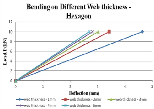
Hexagon
1 2 3 4 5
4.62 3.41 3.01 2.80 2.68
[image:4.595.36.295.119.398.2]Figure 4: Plots of load versus deflection on a different web thickness (type of opening shape – octagon)
Figure 6: Plots of load versus deflection on a different web thickness (type of opening shape – diamond)
[image:5.595.36.296.277.453.2]Figure 7: Plots of load versus deflection on a different web thickness (type of opening shape – square)
[image:5.595.305.559.280.453.2]Figure 8: Plots of load versus deflection on a different web thickness (type of opening shape – triangular)
Figure 9: Plots of load versus deflection on a different web thickness (type of opening shape – trapezoid)
Figure 10: Plots of load versus deflection on a different web thickness (type of opening shape – hexagon)
[image:5.595.309.555.496.670.2] [image:5.595.37.285.498.671.2]load increased significantly with the deflection or in other words, the load is directly proportional with the deflection of the steel section. Therefore, thicker web should be considered for optimum design in bending since the thinner web will cause the increment in deflection.
C. Effect of the Type of Opening Shape
[image:6.595.38.288.293.591.2]The shapes of opening are varies as to investigate the effect of the different type of opening shape on the triangular web profile with opening (TriWP with opening) steel section. The shapes that are considered in this study are circle, octagon, diamond, square, triangular, trapezoid and hexagon. The results of analysis are shown in Table 4 and load versus deflection for each type of opening shape is presented on Figure 11.
Table 4: Deflection results of the bending due to the effect of different type of opening shape
Model (mm) Type of opening
shape
Deflection, δ (mm)
200×100×6×3 Circle 3.29
200×100×6×3 Octagon 2.97
200×100×6×3 Diamond 2.78
200×100×6×3 Square 3.50
200×100×6×3 Triangular 2.89
200×100×6×3 Trapezoid 3.25
200×100×6×3 Hexagon 3.01
Figure 11: Plots of load versus deflection on a different type of opening shape
For steel section of 200×100×6×3 mm (TriWP with opening), it can be noticed that the deflection value for each type of opening shape are varies respectively. It shows that the different type of opening shape will influence the bending behaviour of TriWP with opening. Based on figure 9, the best shape of opening that can resist bending better is diamond compared to that of other shape of opening. Therefore, the type of opening shape should be considered for design in bending.
V. CONCLUSIONS
Corrugated web have more advantages such as to allow the use of thin plate without stiffeners result in reduction in
weight of steel section and stronger strength compared to that I beam section and flat web. However application of the opening is more effective due to its aesthetic architectural appearance with optimum self-weight depth ratio. There are various types, shape and corrugated steel element that has been study by previous researcher and it will continue to find the better in terms of strength and most economical element to use in the industry. Therefore triangular web profile with an opening is introduced as the economical element by reducing weight on the web section in this study. Various mode of failure may occur at or around the opening hence a study using finite element analysis (FEM) will be carried out to investigate the effects of web opening to the steel beam section.
A series of finite element analysis on various geometric properties of triangular web profile steel section with opening, (TriWP with opening) compared with triangular web profile steel section, (TriWP) under bending are carried out by using LUSAS finite element software. Due to effects of each geometric parameter on bending behavior for both types of TriWP steel section with opening and TriWP steel section are observed and investigated in these analysis. The main objective of this study is to determine the bending resistance on the TriWP with opening steel section and it will be compared to that of TriWP steel section with the effect of reduction in weight by introducing opening on the web. Besides that, the different types of opening are also emphasized to determine if the type of opening significantly influence bending behavior on TriWP with opening steel section. It can be concluded that the opening on triangular web profile steel section are significant to the bending strength of the steel section. The introduction of opening shows a greater bending strength compared to triangular web profile steel section.
ACKNOWLEDGMENT
The authors gratefully acknowledge the financial support of Universiti Sains Malaysia (USM), during the course of their research. This research was also made possible by the Research University Grants (RUI) (Account Number: 1001/PAWAM/814222) provided by the Universiti Sains Malaysia.
REFERENCES
[1] W.M.C. McKenzie, “Design of Structural Element to BS 5950,” New York, Macmillan Press Ltd, 2004.
[2] W.M.C. McKenzie, “Design of Structural Steelwork to BS 5950 and C-EC3,” London, Macmillan Press Ltd, 1998.
[3] Y.A. Khalid, C.L. Chan, B.B. Sahari and A.M.S. Hamouda, “Bending Behavior of Corrugated Web Beams,” Journal of Materials Processing Technology, 2004, 150, pp. 242–254.
[5] M. A. Basher, N.E. Shanmugam and A.R. Khalim, “Web Openings in Horizontally Curved Composite Plate Girders,” Journal of Constructional Steel Research, 2009, 65, pp. 1694-1704.
[6] M. Elgaaly, A. Seshadri and R. Hamilton, “Beams with Corrugated Webs, Research to Practice,” Proceedings of
the NSF Research Transformed into Practice:
Implementation Conference. (USA): Arlington, Jun 14-16 1995.
[7] M. Elgaaly and A. Seshadri, “Depicting the Behavior of Girders with Corrugated Webs up to Failure using Non-linear Finite Element Analysis,” Advances in Engineering Software, 1998, 29, pp. 195-208
[8] M. Shahin and M. Elchalakani, “Neural Networks for Modeling Ultimate Pure Bending of Steel Circular Tubes,” Journal of Constructional Steel Research, 2008, 64, pp. 624–633.
[9] C.L. Chan, Y.A. Khalid, B.B. Sahari, and A.M.S
Hamouda, “Finite Element Analysis of Corrugated Web Beams under Bending,” Journal of Constructional Steel Research, 2002, 58, pp. 1391– 1406
[10]S. Nakamura and H. Morishita, “Bending Strength of Concrete-Filled Narrow-Width Ssteel Box Girder,”
Journal of Constructional Steel Research, 2008, 64, pp. 128–133.
[11]H. Hassan, H. Abbas, S. Richard and G. Robert,
“Simplified Analysis of Flange Transverse Bending of Corrugated Web I-girders under In-plane Moment and Shear,” Journal of Engineering Structures, 2007, 29, pp. 2816–2824.
[12]K.S. Kim, D.H. Lee, S.M. Choi, Y.H. Choi, and S.H. Jung “Flexural Behavior of Pre- Stressed Composite Beams with Corrugated Web: Part I. Development and Analysis,” Journal of Composites: Part B, 2011, 42, pp. 1603–1616.
[13]M. H. Osman, A. L. Saleh, A. A. Saim, and F. S. Ween, “Analytical Study on Secondary Bending Moment in Trapezoid Web Beam. In: Analysis, Design and Performance of Steel Section With Trapezoid Web,”
Universiti Teknologi Malaysia, 2008, pp. 26-42, ISBN 978-983-52-0575-0.
[14]M. Basher, N.E. Shanmugam, A.R. Khalim,
“Horizontally Curved Composite Plat Girders with
Trapezoidally Corrugated Webs,” Journal of
Constructional Steel Research, 2011, 67, pp. 947–956.
[15]N.D. Lagaros, L.D. Psarras, M. Papadrakakis, G. Panagiotou, “Optimum Design of Steel Structures with Web Openings,” Engineering Structures, 2008, 30, pp. 2528-2537.
AUTHORS
First Author – De’nan F., Doctor of Philosophy (Ph.D) (Civil Engineering – Steel Structures), School of Civil Engineering, Engineering Campus, Universiti Sains Malaysia, 14300 Nibong Tebal, Pulau Pinang, Malaysia, [email protected]
Second Author – Osman. M.H.,Doctor of Philosophy (Ph.D)
Faculty of Civil Engineering, Universiti
(Structural Eng.),
Teknologi Malaysia, 81310 Skudai, Johor, Malaysia, [email protected]
Third Author – Saad S., Doctor of Philosophy (Ph.D)(Mech.
Faculty of Civil Engineering, Universiti Teknologi Malaysia,
Eng.),
81310 Skudai, Johor, Malaysia, [email protected]
Fourth Author – Hashim N.S., MSc (Civil Engineering), School of Civil Engineering, Engineering Campus, Universiti Sains Malaysia, 14300 Nibong Tebal, Pulau Pinang, Malaysia, [email protected]
Fifth Author – Sharizal N., Researcher (Civil Engineering), School of Civil Engineering, Engineering Campus, Universiti Sains Malaysia, 14300 Nibong Tebal, Pulau Pinang, Malaysia