Design of Cross Flow Turbine and Analysis of Runner's
Dimensions on Various Head and Flow Rate
Myin San*, Nyi Nyi**
*
Department of Mechanical Precision Engineering, University of Technology (Yadanarpon Cyber City) **
Department of Mechanical Precision Engineering, University of Technology (Yadanarpon Cyber City)
DOI: 10.29322/IJSRP.8.8.2018.p8076 http://dx.doi.org/10.29322/IJSRP.8.8.2018.p8076
Abstract- There are various natural resources such as water, air, wind and solar in Myanmar. Among them, water resource is the most abundant as there are many rivers and streams with rich electrical energy. Moreover, the cost of hydro-electric power is relatively cheaper compared with other resources. In hydropower systems, hydraulic turbine is one of the most important parts to generate electricity. This paper represents the runner design of Cross-flow turbine that will generate 100 kW output power from head of 28 m and flow rate of 0.5 m3/s. For these head and capacity, rotational speed is 600 rpm, specific speed is 95.39, runner diameter is 340 mm and runner width is 416 mm. In this paper, detail design drawing of runner are also clearly presented. Moreover, the runner's diameter and breadth are represented with various flow rate range of 0.2 to 1 m3/s and head range of 10 m to 50 m. Thus, it is easy to select the suitable runner's dimensions on the corresponding head and flow rate.
Index Terms- Cross-flow turbine, head, flow rate, output power, blade curvature, runner's dimensions I. INTRODUCTION
N Myanmar, hydropower is the main sources of energy for electricity because there are many hilly regions with river and water falls. Myanmar, where 75% of the populations live in rural area has a low level of village access to electricity. It has abundant hydro energy sources and the Geography, Topography of the country is favorable for hydropower supply system. A hydropower classified into run-of-river type and reservoir type.The main advantages of hydropower are: (1) The power is usually available when needed, (2) The amount of energy proportional to the head, (3) No air pollution or radioactive-waste problem, (4) No contribution to global warming and (5) One of the most effective solutions of the production of electricity.
According to above mentioned particulars, there are three types of hydropower plants, such as micro, mini and small hydropower plants. The powerdepends on the amount of water flowing and the height from which it flows down the pipe to the turbine. There are two types of turbine used in hydropower plant, and these are impulse and reaction types. The Cross-flow turbine is an impulse type and
it
is used for low and medium head site. Moreover, it is very suitable for micro and mini hydropower generation because of the quitesimple to construct and the capability following wide fluctuation of water flow.II. WORKING PRINCIPLE AND COMPONENTS OF CROSS-FLOW TURBINE
[image:1.612.161.444.572.722.2]Cross-flow turbine type has a drum shaped runner made of a series of curved blades fixed on two parallel disks. In this turbine, the water velocity is compound of two stages. The jet of water flows firstly from outside to inside of the runner. After crossing the interior of the runner, it flows inside to outside of the runner again.
Fig. 1 Main Components of Cross-flow Turbine [1]
Before designing the turbine, the components, operation principle and performance characteristics must be studied. Main components of cross-flow turbine are nozzle, runner, shaft, bearing, casing, draft tube, guide vane and air valve. In this turbine, nozzle is rectangular shape that its width matches the width of runner. Its primary function is to convert the total available head into kinetic energy and simultaneously convey the water to the runner blades at a desired angle. The turbine casing must be well built and sturdy, as it manages forces of the incoming water as well as the outgoing shaft power. Casing shape and dimensions have a significant effect on efficiency. Draft tube is attached below the casing. In order to utilize the draft effect, the tube end is submerged under the tail water level. Its function to recover a major portion of the residual energy left in the water flow coming out of the runner, the head between the turbine and tail water. The shaft is the component of mechanical devices that is used to transmit power from hydraulic power to mechanical power. The runner is one of the most important parts of the turbine. The function of runner is responsible for the conversion of water energy into mechanical energy. Blades are curved and mounted between two rims parallel to the axis of the shaft. Their function is to change the direction of the incoming flow from the nozzle smoothly.The curvature of each surface, front and rear, determines how the water will push its way around until it falls away. All runners should be carefully balances to minimize vibration, a problem that not only affects efficiency but can also cause damage over time. The runner of the cross-flow turbine is made up of two end plates, a shaft and 24 to 30 blades arranges radically around the end plates.
The diameter of runner is an important and basic factor for the design of runner. It can be determined from the speed and water head. From the turbine speed, generator can be selected for the synchronous speed. In this paper, the inlet flow angle to the runner is taken as 16° according to Banki’s design. When considering the design of runner, the curvature of blade, inlet blade angle, the pitch value and the thickness of blade must be considered. The thickness of blade depends on the diameter of the runner.
If the speed of turbine is too low, the speed increaser must be used to increase the speed. But it is necessary to consider not only the force of the water which strike the runner, but also own weight of the runner.
Fig.2 Water Flow Path through the Runner and Velocity Diagram [2]
III. DESIGN OF CROSS FLOW TURBINE
In this paper, the required design data are based on Chi Chaung Hydropower project in Chin State, Myanmar and design specifications are as follow.
Effective head, H = 28 m Expected output power, P
g= 100 kW
Efficiency of turbine, η
T= 80%
Efficiency of generator, η
G= 95%
Overall efficiency, η
o = ηT × ηG = 76%
Density of water, ρ= 1000 kg/m3 Acceleration due to gravity, g = 9.81 m/s2
The 100 kW turbine is within the range of Mini-hydropower plant and the required flow rate of this turbine can be determined by using power equation.
Flow rate,
o γ H
g P Q
η
= (1)
By Equation (1), the required flow for expected output power is 0.5 m3/s.
A. Suitable Turbine Type Selection
[image:3.612.220.403.331.515.2]Firstly, suitable type of turbine that will be used must be determined based on the design flow rate and effective head. According to the Fig. 3, the design turbine of effective head 28 m and flow rate 0.5 m3/s for the expected power 100 kW is within the ranges of Cross-Flow turbine type. Thus, for the design flow rate and head, Cross-flow turbine type is selected.
Fig. 3 Selection of Turbine Type [4]
B. Determination of Specific Speed and Rotational Speed
To determine the basic dimensions of turbine easily, the value of specific speed must be known. Specific speed of a turbine is the speed of a geometrically similar turbine which would develop unit power (metric) when working under a head of one meter. Specific speed also plays in an important role for the selection of turbine type. And also the performance of turbine can be predicted and the fundamental dimensions of the turbine can be easily estimated based on the specific speed value of turbine. For Cross-flow turbine, the range of specific speed is 40≤Ns≤200 [2]. Applicable maximum specific speed is
5 0
max 650
.
-s H
N
≤
(2)The applicable maximum specific speed is 122.8 and specific speed formula by Kpordze and Warnick, 1983, is
505 . 0
55 . 513
H s
N = (3)
The calculated specific speed, 95.39 is within the range 40 and 200, and less than the applicable maximum value of specific speed 122.8.
directly or through a speed increaser to the turbine, should reach the synchronous speed. The rotational speed of turbine is P H N N s 4 5
= (4)
In the hydro scheme, standard generator is installed when it is possible, either directly coupling or through a speed increaser should reach the synchronous speed. The number of pole for synchronous speed generator is always even number and it is expressed by
N f
Po = 120 (5)
Where, f is frequency (50 Hz).
C. Determination of Runner Diameter and Breadth
Runner is the main component of the turbine that converts water power to shaft power. So, the shape and dimensions of runner are very important in any turbine. For the maximum efficiency, η
maxthe periphery velocity of the wheel U is 0.5V. However, in actual
practice, the maximum efficiency occurs when the value of U is about 0.46V. Therefore, the periphery velocity of the wheel can be determined as follow:
1 1 1
V U
ku = (6)
60
1 1
N D
U = π (7)
gH k
V1 = c 2 (8)
where,
ku1= coefficient of rotational velocity (0.4 ~ 0.5)
kc= coefficient of water velocity (0.92 ~ 0.99)
D1= diameter of runner (m)
When kcand ku1are chosen as 0.98 and 0.46 respectively, runner diameter D1 can be determined by Equations (6), (7) and (8).
Breadth of the runner depends on the jet thickness and water inflow velocity. The thickness of the jet, So is 0.1 to 0.2 times of
runner diameter. By taking the average nearly,
1
17 . 0 D
So = (9)
The total area of jet can be determined by using continuity equation,
gH k L S AV
Q= 1 = o × × c 2
Thus, the breadth of runner is
gH k L S Q L c o × × 2
= (10)
In this design, the runner has middle disk and the real breadth of runner must be added 10% more [2]. Thus, Real breadth of runner is
L1 = L + 0.1 L (11)
After determining the dimensions of runner diameter and breadth, it needs to check the ratio of runner breadth to runner diameter. Not to poor the runner proportions, this ratio must be within the following range.
85 0 1
1 2124
16 0 . H . D L
. ≤ ≤ (12)
If this ratio isn’t within the range, runner diameter or breadth must be increased or decreased by trial and error method until it is satisfied.
D. Required Parameters of Blade Curvature
Fig 4. Curvature of Blade
Where, Outer radius of runner, R1 = D1/2 (13)
Inner radius of runner, R2 = D1/3 (14)
Radius of blade shaped arc, r = 0.16 D1 (15)
Radius of circle of center pitch of shaped arc, Ro2 = R22 +r2 (16) Blade pitch,
Z R P
P1 2 = 2π o (17)
The number of blades, Z is (24 ≤ Z≤30) and the fewer blades may cause pulsating power, while a larger number of blades may cause excessive friction losses. So, the number of blades is chosen as 26 blades in this design.
E. Blade Thickness (t)
The thickness of the blade depends on the diameter of runner and the relationship between them is shown in Table I. In this design, the calculated runner diameter is 430 mm and so, the thickness of the blade is chosen as 6 mm.
Table I. Runner Diameter and Blade Thickness
[2]
Runner Diameter (mm) 200 300 450 700 1000 Thickness of Blade (mm) 3.2 4.5 ~ 6 6 9 12
F. Prediction of Shaft Diameter
The turbine shaft will transmit the rotary motion of the runner to the generator via the drive system. In most cases, the shaft has a circular cross-section and it subject to either pure torsion or a combination of torsion and bending. The shaft diameter is estimated by
3 150
N P
ds = (18)
Since it is difficult to predict the bending moment at this time, the shaft diameter will be increased slightly.
G. Determination of Penstock Diameter and Thickness
The required diameter of penstock (dp) can be estimated by the following equation. 5
. 0
785 .
0
=
V Q
dp (19)
where,
gH V = 0.2 2
Q = discharge in the penstock (m3/s)
V = velocity of water in the penstock (m/s)
The thickness of penstock (tp) should be greater than 6 mm and it can be determined by the following expression.
400 800
+
= p
p
d
t (20)
[image:5.612.40.533.502.730.2]IV. RESULTS OF RUNNER DESIGN
Table II. The Calculated Result for Cross-Flow Turbine
Power
Breadth of runner Diameter of runner Internal diameter of runner Radius of blade shaped arc Radius of circle of center pitch Blade pitch
Blade thickness No. of blades Diameter of shaft Diameter of penstock Turbine speed No. of pole
Expected Efficiency
P L1
D1
D2
r Ro
P1P2
t z ds
dp
N Po
η
100 kW 415 mm 340 mm 227 mm 54 mm 126 mm 30.4 mm 6 mm 26
90 mm 400 mm 600 rpm 10 88 %
The calculated results of especially runner design for 100 kW Cross-flow turbine based on head of 28 m, water flow rate of 0.5 m3/s and turbine rotational speed of 600 rpm are clearly expressed in Table II. Moreover, detail drawings of blade curvature and runner design are also shown in following figures.
Fig 5. Side View and Front View of Runner
V. ANALYSIS OF RUNNER'S DIMENSION AND OUTPUT POWER
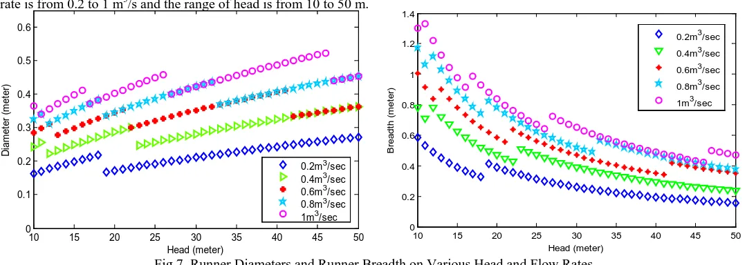
In this studying, runner diameter and breadth and output power are analyzed by varying flow rate and head. The range of flow rate is from 0.2 to 1 m3/s and the range of head is from 10 to 50 m.
[image:7.612.36.576.88.280.2]
Fig 7. Runner Diameters and Runner Breadth on Various Head and Flow Rates VI. CONCLUSION
For high demand electricity, the Cross-flow turbine is used for rural areas and the place which is far from the grid system. It can be used for low and medium head of water using simple technology that can be locally designed and easily built, with mainly local materials at low cost. In this paper, Cross-flow turbine is designed for 28 m of head and 0.5 m3/s of flow rate to generate 100 kW. To design the runner, some parameters of Cross-flow turbine are assumed. In this design, the water inlet flow angle to the wheel is taken as 16º to get optimal efficiency according to Banki's design. By using this inlet flow angle, the inlet blade angle has been determined. The diameter of the designed runner is 340 mm and the breath of runner is 415 mm. In this turbine, the number of blade is 26 and the thickness is 6 mm. The blade can also be cut out of thin-wall tubes, or made of strips of thin sheet metal rolled around a pipe. The diameter of shaft is 90 mm and penstock is 400 mm for this turbine. A synchronous generator 10 pole will be used by the direct coupling system. Moreover, diameter and breadth of the turbine runner are also analyzed by varying the head and flow rate. In this studying, the varying head range and flow rate range are from 10 to 50 m and from 0.2 to 1 m3/s respectively. Because of this analyzing, the suitable runner's diameter and breadth can be chosen easily within these operation ranges for cross flow turbine type.
ACKNOWLEDGMENT
The author especially thanks to Dr. Nyi Nyi, Professor, Department of Mechanical Precision Engineering, University of Technology (Yadanarpon Cyber City) for his kind supervision, suggestion and valuable guidance of this paper.
REFERENCES
[1] Hitoshi Yamamoto. 1983. “Cross-Flow Hydraulic Turbine and their Power Generating Systems”, Series.68. Japan.
[2] Mockmore.C.A. & Merry field. F. 1949. “The Banki Water Turbine”, Bulletin series. No.25, Oregon state college, Corvallis, USA. [3] The British Hydropower Association, January 2005, "A Guide to UK Mini Hydro Development".
[4] Celso Penche and Ingeniero de Minas, 1998, "Layman's Guide Book", How to Develop a Small Hydro Site. [5] Khin Maung Aye. 1997. “Cross-Flow Turbine for Mini-Hydropower Plant”, M.Phip, Research Paper. Y.T.U.
[6] Institute of Energy Economics. 2003. “Study on Introduction of Renewable Energies in Rural Area in Myanmar”, Nippon Koei Co., Ltd. Japan.
[7] Vincenzo Sammartano, Costanza Arico, Armando Carravetta, Oreste Fecarotta and Tullio Tucciarelli "Banki-Michell Optimal Design by Coputational Fluid Dynamics Testing and Hydrodynamic Analysis", energies journal, ISSN 1996-1073, 2013.
[8] Caner AKCAN, Mahmut F. AKSIT and Serdar AKSOY, "Reoponse Surface Modeling of a Small Crossflow Hydro Turbine Rotor".
AUTHORS
First Author – Myint San, Lecturer, Department of Mechanical Precision Engineering, University of Technology (Yadanarbon Cyber City and komyintsan@gmail.com.
Second Author – Nyi Nyi, Professor, Department of Mechanical Precision Engineering, University of Technology (Yadanarbon Cyber City and
yaytakon@gmail.com.
10 15 20 25 30 35 40 45 50 0 0.2 0.4 0.6 0.8 1 1.2 1.4 Head (meter) B readt h ( m et er )
0.2m3/sec 0.4m3/sec 0.6m3/sec 0.8m3/sec 1m3/sec
10 15 20 25 30 35 40 45 50 0 0.1 0.2 0.3 0.4 0.5 0.6 Head (meter) D iam et er ( m et er )
![Fig. 1 Main Components of Cross-flow Turbine [1]](https://thumb-us.123doks.com/thumbv2/123dok_us/9069370.978874/1.612.161.444.572.722/fig-main-components-cross-flow-turbine.webp)
![Fig. 3 Selection of Turbine Type [4]](https://thumb-us.123doks.com/thumbv2/123dok_us/9069370.978874/3.612.220.403.331.515/fig-selection-of-turbine-type.webp)